
milling a radius on a rotary table in stock

This website or its third-party tools process personal data (e.g. browsing data or IP addresses) and use cookies or other identifiers, which are necessary for its functioning and required to achieve the purposes illustrated in the cookie policy. To learn more, please refer to the cookie policy. In case of sale of your personal information, you may opt out by sending us an email via our Contact Us page. To find out more about the categories of personal information collected and the purposes for which such information will be used, please refer to our privacy policy. You accept the use of cookies or other identifiers by closing or dismissing this notice, by scrolling this page, by clicking a link or button or by continuing to browse otherwise.

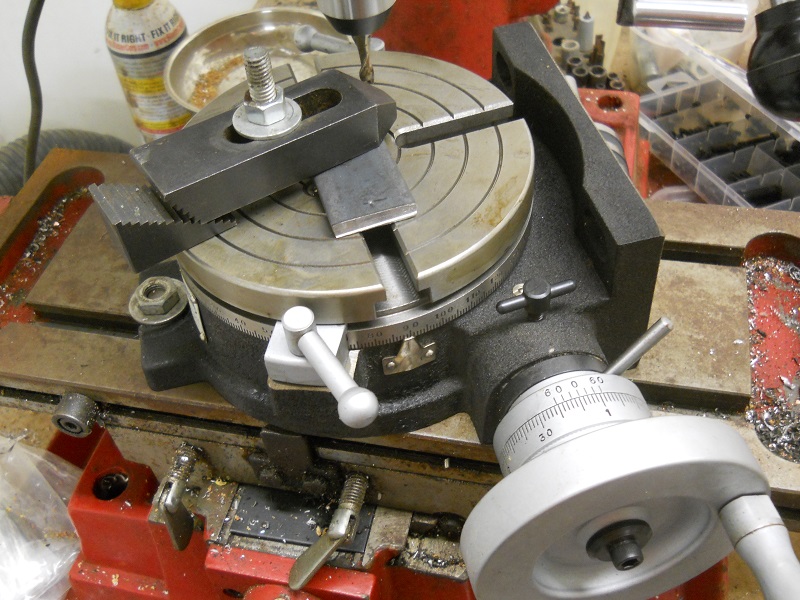
2. Depending on the type of mill, round column or knee, provide enough head space to indicate the center of the rotary table and still get a cutter to the workpiece.
3. Mount your part. If the part is irregular shaped sometimes it"s easier to make up a mounting plate to fasten the part to. This way you can move the part to center and then clamp the plate in place.
6. For a part similar to what you"re showing you will also need to have a layout line that runs across the piece. Once you have the part on center square up the layout line by rotating the table as you move from end to end on the layout line. (with a wiggler)
9. Move one axis off center and then move the table back toward the part until the cutter starts to cut. Before you cut you should know what calculated degree of angle you will need to stop the radius at. This will be the blend point between the radius and the straight wall.
10. Start cutting your radius. Generally I stay about 1/2 degree away from my tangent point until I get the radius to where I want it. This will prevent the cutter from digging in and leaving a mark where the tangent point is. After you have the radius milled rotate the table to the appropriate angle and mill the straight sides. There will be a small amount of stock where you stayed shy of the angle when cutting the radius.
11. Now for your final cut, rotate the table so that your straight cut will be a climb cut. Take a finish pass along the straight wall until you axis dial reads -0-. Rotate the table the required amount until you get to the other tangent angle, lock the rotary table and then make your final straight cut.

1. Build a fixture that will locate the aluminum on the rotary table so I can repeatedly use the same setup without indicating for each of the 4 corners on each piece and each of the pieces in the lot. The fixture will also hold the work piece about 1/4" above the table surface to keep it from being damaged during machining.
3. Bolt that fixture to the rotary table such that each piece to be cut will be located with the center-line of the corner radius right on top of the rotational center of the table.
7. Advance the table further left some to avoid taking too big of cut and drop the quill down so the end mill will cut the entire thickness of the 1/4" aluminum on each pass.
Anyway...I"m a beginner at all of this and this is just what I came up with in my head. Hoping someone has a better way! (i.e. an easier way). These aluminum pieces are decorative...and they need to look right but really tolerances aren"t all that critical.

No expert here, but I"ve already learned the hard way that the setup you show will not work. You need to A) realise that the cutting forces at play are very large, B) that metal on metal doesn"t actually add up to that much friction, and C) you need something to stop the part from sliding rather than just holding it down.
At the very, very least, you could rotate the bar such that it was not over-top the T-slot. Then, you could bolt something in the T-slot such that the bar can push up against the side of it. Maybe do the same to the other end of the bar with the other T-slot. That way, when the endmill pushes into the bar, the bar will push against said bolt. Nothing to push against and it will just slide out of the way.
Better, as other"s have said, use 2 clamps, with the bolts holding said clamps down going up against the edge of your metal bar. Orientate them such that said bolts oppose the cutting forces. Then, all you have to worry about is the bar getting dragged out lengthwise.
It gets easier after a while... you clamp something down and, with experience, that little voice in your head goes "nope." Some days, you listen to that voice and find a better way
Rotary tables look cool and are fun to play with, but they"re finicky to get anything decent out of them. You have to zero the table in the mill, then zero the part on the table, and then get all the clamps in place but out of the way... Everything has to be really solid or the endmill will chatter and the cut will look lousy. Then you have to wind back and forth, back and forth... I"d scribe a line and abrade down to it with a belt sander, if I wanted a nice looking job. If I was in a rush, I"d probably just clamp an appropriate-sized washer to the end in a vice and then file up to it. Be done in less time than it would take to bolt the rotary table to the mill. There are so many ways to accomplish a given task.

VEVOR is a leading brand that specializes in equipment and tools. Along with thousands of motivated employees, VEVOR is dedicated to providing our customers with tough equipment & tools at incredibly low prices. Today, VEVOR has occupied markets of more than 200 countries with 10 million plus global members.
VEVOR is a leading brand that specializes in equipment and tools. Along with thousands of motivated employees, VEVOR is dedicated to providing our customers with tough equipment & tools at incredibly low prices. Today, VEVOR has occupied markets of more than 200 countries with 10 million plus global members.
The mill rotary table is one of the main accessories of milling machine. As a precision work positioning device, it is widely used for indexing drilling, milling, circumferential cutting, boring, etc. The rotary turn table for milling machine is made from HT200 casting with high quality. It has already passed the ISO9001 quality system certification. They are are very popular on the market for their superior performance, excellent design and reasonable cost.
Both vertical and horizontal with two functions. Circle cutting, indexing drilling, milling and more complicated work are possible when the vertical position of the table is used together with the tail part.
The possibilities are endless with the SB1364 6" Rotary Table as you repeatedly cut circular slots, radius corners and drill any pattern of holes. It was designed with a MT#2 Morse taper and can be mounted vertically or horizontally depending on your needs.
The handwheel scales, degree and vernier, can be easily aligned with each other and adjusted for easy viewing. The vernier scale is used to measure table rotation by ten arc seconds at a time.
When fully tightened, the table locks keep the table from rotating to reduce the strain on the gears during operation. The backlash adjustment lock secures the backlash adjustment ring in place. The backlash adjustment ring lever controls the backlash adjustment ring for adjusting the backlash between the gears.
The manual was written by our U.S. based Technical Documentation Department and is packed with useful information. The complete and easy to read manual provides full instructions on how to assemble and maintain your rotary table.
Like all South Bend products, it comes with a 2-year warranty which covers parts and assures the unit is free from factory defects. Since many of the parts are machined to each individual chuck, they may not be available as replacement items.
The South Bend Customer Service and Technical Support Teams are U.S. based. Parts and accessories for the chuck are available on-line and shipped from the South Bend parts warehouse in Springfield, MO.

The channel for the slide needs to be positioned in a manner that the back of the slide is 1.98 inches away from the 3 inch point of the rotary table. And 3 inches minus 1.980 is 1.02 (3.0 - 1.980 = 1.02) so the rear of the channel needs to be machined 1.02 inches away from the center.
If you mill that channel 1.01 inches wide and so that it stops 1.02 inches from the middle of the rotary table, you should be able to set the slide in the channel so that the rotary table generates the 3 inch front radius of the RM06 in the correct position.
You"ll need to machine a hold down system for the slide. I like to use a drilled hole through where the chamber would be and bolt through a plate that holds down the slide .
Once you have the slide positioned correctly and bolted down to your fixture, you’ll need to use an indicator to make sure the slide is perfectly straight. Adjust the straightness on your rotary table until there"s no run-out along the x axis.
Start machining the radius by using the rotary table to move the slide rather than the x/y movement of your table. Do so in 5000th increments. Machine it closer and closer to the 3 inch radius in these small increments.
If you are interested in doing the recoil lugs, you can do it with a custom made annular cutter. Or you can drill a hole in the location of the recoil lug in the same diameter, and then press a pin into the hole so it sits proud.
We hope you enjoyed this week’s blog. Thank you for following along! New posts are released every Tuesday at 10am PST. Please comment for any content you want to see.
If you loved the services you saw today, check out our online store! You can start shopping by clicking here. Or drop us a message here. We look forward to meeting you and gunsmithing for you.

·Typical use cases include machining the flutes of a milling cutter, cutting the teeth of a gear, milling curved slots, or drilling a bolt hole circle around the circumference of a part.


 8613371530291