
milling a radius on a rotary table free sample

This website or its third-party tools process personal data (e.g. browsing data or IP addresses) and use cookies or other identifiers, which are necessary for its functioning and required to achieve the purposes illustrated in the cookie policy. To learn more, please refer to the cookie policy. In case of sale of your personal information, you may opt out by sending us an email via our Contact Us page. To find out more about the categories of personal information collected and the purposes for which such information will be used, please refer to our privacy policy. You accept the use of cookies or other identifiers by closing or dismissing this notice, by scrolling this page, by clicking a link or button or by continuing to browse otherwise.

VEVOR is a leading brand that specializes in equipment and tools. Along with thousands of motivated employees, VEVOR is dedicated to providing our customers with tough equipment & tools at incredibly low prices. Today, VEVOR has occupied markets of more than 200 countries with 10 million plus global members.
VEVOR is a leading brand that specializes in equipment and tools. Along with thousands of motivated employees, VEVOR is dedicated to providing our customers with tough equipment & tools at incredibly low prices. Today, VEVOR has occupied markets of more than 200 countries with 10 million plus global members.
The mill rotary table is one of the main accessories of milling machine. As a precision work positioning device, it is widely used for indexing drilling, milling, circumferential cutting, boring, etc. The rotary turn table for milling machine is made from casting with high quality, can work with a set of dividing plate.
Both vertical and horizontal with two functions. Circle cutting, indexing drilling, milling and more complicated work are possible when the vertical position of the table is used together with the tail part.
Three dividing plate set(Plate "A" - 15, 16, 17, 18, 19, 20 Plate "B" - 21, 23, 27, 29, 31, 33 Plate "C" - 37, 39, 41, 43, 47, 49). A set of wrench and screws are free for you with your installation.
These G codes are used to specify circular motion. Two axes are necessary to complete circular motion and the correct plane, G17-G19, must be used. There are two methods of commanding a G02 or G03, the first is using the I, J, K addresses and the second is using the R address.
I, J and K address are used to locate the arc center in relation to the start point. In other words, the I, J, K addresses are the distances from the starting point to the center of the circle. Only the I, J, or K specific to the selected plane are allowed (G17 uses IJ, G18 uses IK and G19 uses JK). The X, Y, and Z commands specify the end point of the arc. If the X, Y, and Z location for the selected plane is not specified, the endpoint of the arc is the same as the starting point for that axis.
To cut a full circle the I, J, K addresses must be used; using an R address will not work. To cut a full circle, do not specify an ending point (X, Y, and Z ); program I, J, or K to define the center of the circle. For example:
The R-value defines the distance from the starting point to the center of the circle. Use a positive R-value for radii of 180 or less, and a negative R-value for radii more than 180.
Thread milling uses a standard G02 or G03 move to create the circular move in X-Y, then adds a Z move on the same block to create the thread pitch. This generates one turn of the thread;
Use a G03 to cut I.D. threads or a G02 to cut O.D. threads. An I.D. right hand thread will move up in the Z-Axis by the amount of one thread pitch. An O.D. right hand thread will move down in the Z-Axis by the amount of one thread pitch. PITCH = 1/Threads per inch (Example - 1.0 divided by 8 TPI = .125)
The next step is to program a complete circle (G02 or G03) with a Z-Axis command of the amount of one full pitch of the thread (this is called Helical Interpolation).
You cannot turn cutter compensation off or on during an arc movement. You must program a linear move, either in the X or Y Axis, to move the tool to and from the diameter to cut. This move will be the maximum compensation amount that you can adjust.
Outside Diameter (O.D.) Thread MillingO.D. Thread Milling Example, 2.0 diameter post x 16 TPI: [1] Tool Path [2] Rapid Positioning, Turn on and off cutter compensation, [3] Start Position, [4] Arc with Z.
This program is for a 1.0" diameter hole with a cutter diameter of 0.500" and a thread pitch of 0.125 (8TPI). This program positions itself in Absolute G90 and then switches to G91 Incremental mode on line N7.
Helical (spiral) motion is possible with G02 or G03 by programming the linear axis that is not in the selected plane. This third axis will be moved along the specified axis in a linear manner, while the other two axes will be moved in the circular motion. The speed of each axis will be controlled so that the helical rate matches the programmed feedrate.

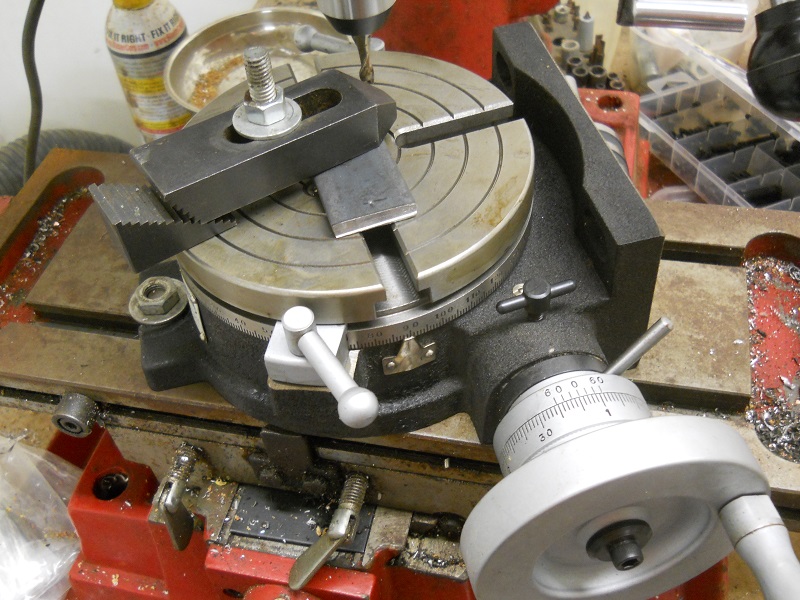
I usually get a good many arguments started about rotary table setups. I worked in a large forge die shop, and I still do the setups the way we were shown in that shop. Probably 95% of the time you used a rotary table on a rotary head milling machine, so getting stuff on center was step #1.
The first thing to be pointed out is that the center hole and OD of the table aren"t necessarily on the axis of rotation. Easy to check, take the worm out of engagement and pull the table around by hand with an indicator zeroed on the center hole. Just like indicating a part in a four jaw.
If it is on center, that"s great. If not, you can eyeball your part on center and lightly clamp while you indicate it in by pulling the table around by hand and tapping it. If you don"t have a concentric hole or OD to use an indicator on, a center punch mark and a pump center can be used.
Once the part is on the center of the rotary tables axis, it"s a simple matter to center it under the machine spindle by locking the table and rotating the machine spindle and indicating like you would normally.


 8613371530291