
milling a radius on a rotary table brands

when I was young, strong, healthy, and thought nothing of lifting it, a 10" H & V was my first choice. I still think it was a good choice for the work I mostly do, and this is where you may decide to compromise. If you do small work, an 8" table is much lighter and more convenient to set up. Stood vertical, it interferes less with the spindle to reach center. I don"t think a 6" is a good choice unless you know you will only be working miniature stuff. You use a considerable percentage of a small table just for set ups and hold down clamps on a lot of work, and a small table does not leave much room.
I like 90:1 gear ratio for circular milling, which is presumably your primary interest with a rotary table. My 10" table is 90:1, and that is a pretty good ratio for milling diameters (hand cranking) out to 12" or so. My 20" table is also only 90:1, and out near or past the rim (I do one part at 32" diameter) that always seems _very_ coarse.
If most of your work is small, round to begin with, and will actually be dividing work, where you index the table, lock it, and then drill a hole or mill a slot with the machine axis drive, you might find a dividing head more useful. For instance, I"ve made gears on a vertical rotary table, and in a spin index. On the table, you need an insert collet chuck or other arrangement in the center hole to get the work out far enough to clear the cutter. It"s a lot more convenient on a dividing head. OTOH, I don"t find it fun or convenient to do much circular milling on a dividing head if the work diameter is much over a few inches.
Dividing heads typically are 40:1, so faster to index, position to positon. But the milling capability on a radius is limited by the "coarse" ratio to smaller diameters, as is the usual work holding (collet or chuck) arrangement. A dividing head will tilt from below horizontal to past vertical, so you can mill, drill, bore or shape profiles at any angle in between.
an 8" H & V with dividing plates and set up, can usually be arranged somehow to do most of the work you might want to do on it. It is relatively light to move, and convenient to set up with reasonable space (spindle clearance, e.g.)limitations to be considered. A little bigger (10") is better, if you will ever need the capacity.

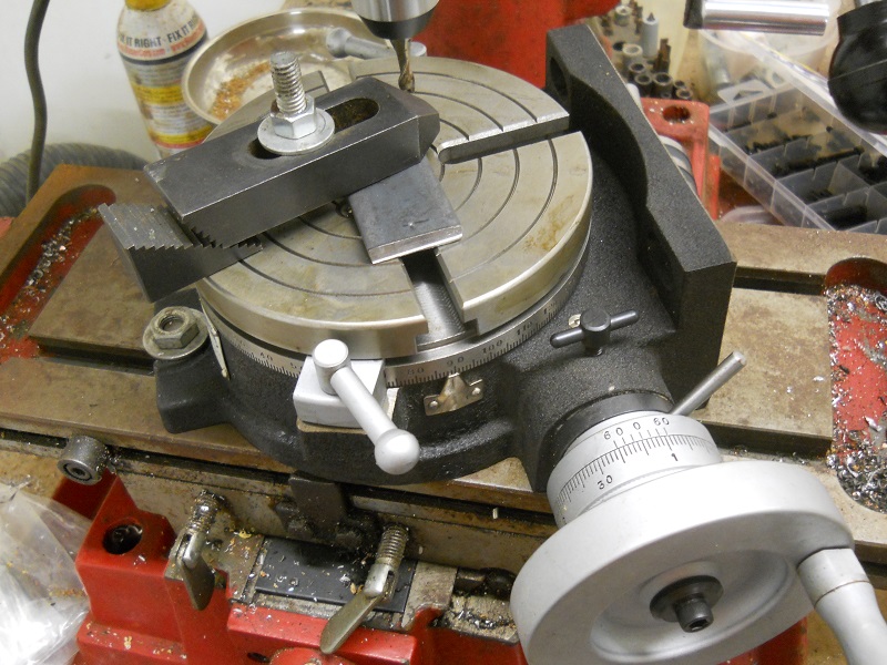
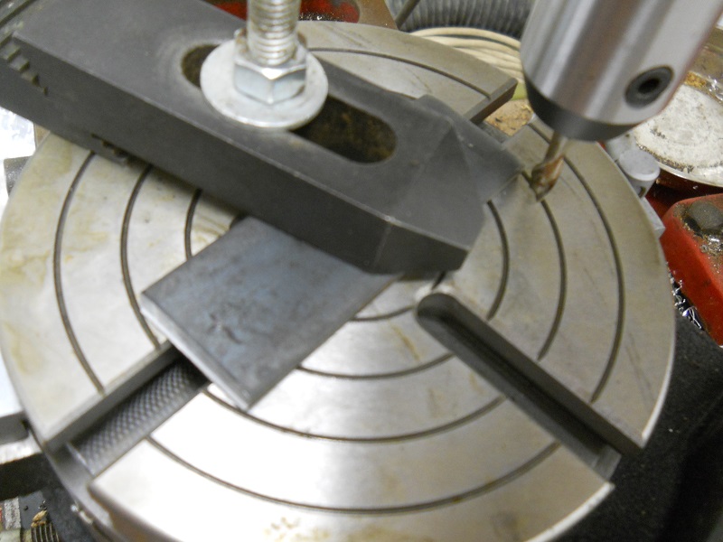
I usually get a good many arguments started about rotary table setups. I worked in a large forge die shop, and I still do the setups the way we were shown in that shop. Probably 95% of the time you used a rotary table on a rotary head milling machine, so getting stuff on center was step #1.
The first thing to be pointed out is that the center hole and OD of the table aren"t necessarily on the axis of rotation. Easy to check, take the worm out of engagement and pull the table around by hand with an indicator zeroed on the center hole. Just like indicating a part in a four jaw.
If it is on center, that"s great. If not, you can eyeball your part on center and lightly clamp while you indicate it in by pulling the table around by hand and tapping it. If you don"t have a concentric hole or OD to use an indicator on, a center punch mark and a pump center can be used.
Once the part is on the center of the rotary tables axis, it"s a simple matter to center it under the machine spindle by locking the table and rotating the machine spindle and indicating like you would normally.

The TR160 5 Axis Rotary Tables, manufactured by Haas, consist of dual axis Trunnion rotary table that is capable of tilting up to 160 mm. It also has a scale assessment ...
The TR210 is HAAS"S rotary table developed and configured to be integrated with HAAS"S mills 4th and 5th axis drivers to provide complete and optimum operation. It has a diameter of 210 mm made from trunnion ...
... space with high load capacity. The individual rotary tables are equipped with Harmonic Drive units, which ensure high moment load capacities and high concentricity and axial runout accuracies.
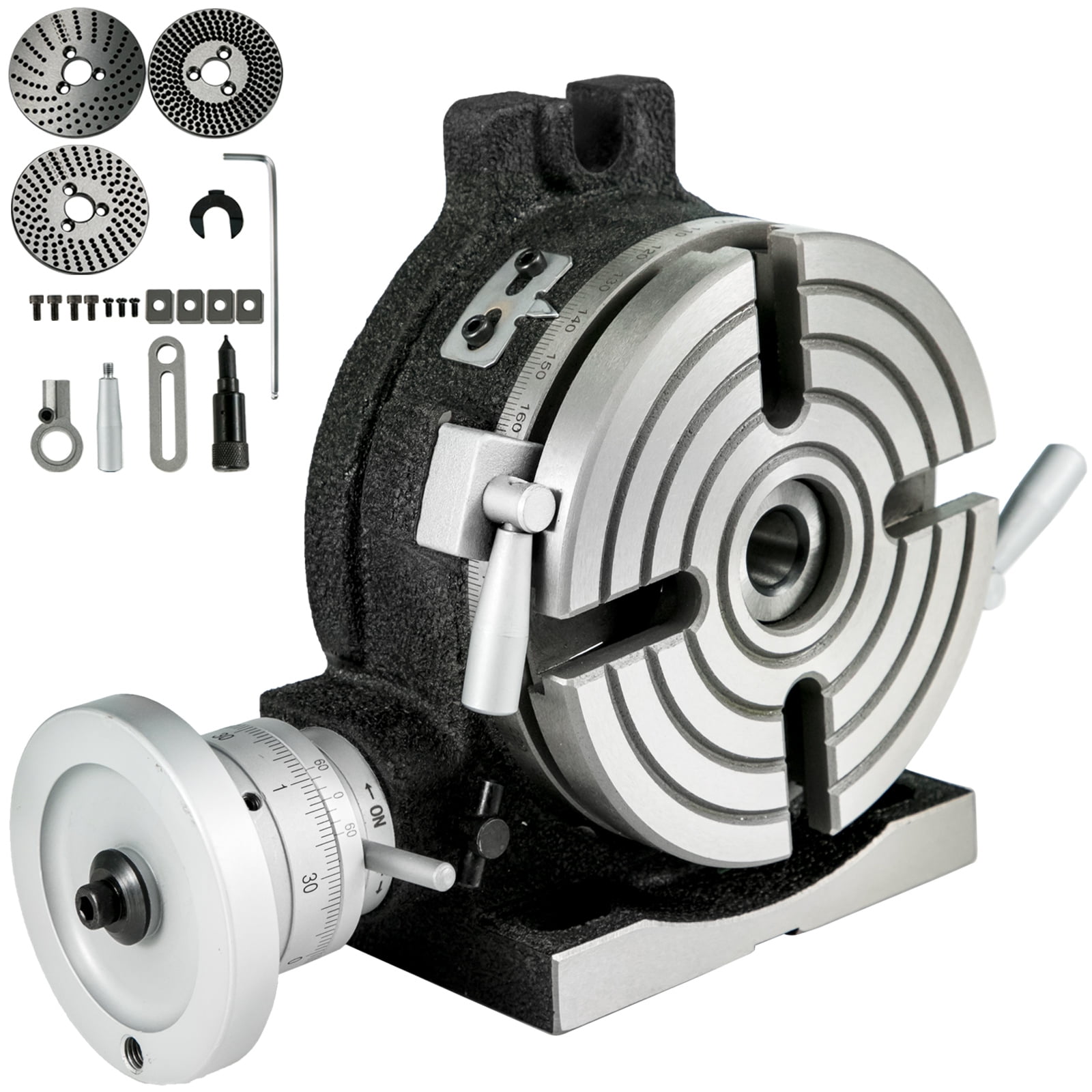
The work table is graduated 360 degrees around its circumference and is driven by a precision Worm and Gear providing a 90:1 reduction ratio. One turn of the Handle moves the Table through 4 degrees. ...
... Tilt-Yaw (A/B) two-axis rotary assembly provides high-speed machining capabilities for complex 3D part geometries. The precision-aligned system allows accurate positioning on a hemispherical surface. ...
... ) MDR two-axis rotary assembly provides high-speed machining capabilities for complex 3D part geometries. The precision-aligned system allows accurate positioning on a hemispherical surface. Uses cost-effective ...
... ) MDR two-axis rotary assembly provides high-speed machining capabilities for complex 3D part geometries. The precision-aligned system allows accurate positioning on a hemispherical surface. Uses cost-effective ...
Our FÖRSTER swivel welding tables offer maximum working comfort for all-round welding of complex assemblies. Ideal for all tasks due to a variable arrangement of our patented T-slot system.
The hydrostatic rotary tables from ZOLLERN impress with their durability and a high concentricity and axial runout accuracy. Thanks to the ZOLLERN bearing clearance compensator, the optimal pocket pressure ...
... the table is the rotation, the user may require the rotary table for drilling operations and milling. Using the servo drives in conjunction with the machine CNC control ...
With DirectIndustry you can: Find the product, subcontractor or service provider you need | Find a nearby distributor or reseller| Contact the manufacturer to get a quote or a price | Examine product characteristics and technical specifications for major brands | View PDF catalogues and other online documentation
we parag machine tools ar the leading suppliers in this industry we provide material of best quality and best price possible our goal is to provide customer satisfaction
Our company is a prominent in the industry as a manufactures and supplies Rotary Table. We offer our product in diverse specifications to fulfill the differentread more...
Waluj, Aurangabad D1 C 270, Udyog Bharati Estate C/o,Udyog Bharti Estate,Mahaveer Chowk, Near Hotel Dream Line Phase No-3, Plot No.-X340,Waluj,, Waluj, Aurangabad - 431136, Dist. Aurangabad, Maharashtra
Shivaji Udyam Nagar, Kolhapur A-249, Kagal Hatkanangale, Five Star MIDC Kagal, Village Halsawade, Shivaji Udyam Nagar, Kolhapur - 416203, Dist. Kolhapur, Maharashtra
George Town, Chennai 1ST FLOOR OLD NO.68, NEW NO.100/F ARMENIAN STREET, GEORGE TOWN Chenna, George Town, Chennai - 600001, Dist. Chennai, Tamil Nadu
·Typical use cases include machining the flutes of a milling cutter, cutting the teeth of a gear, milling curved slots, or drilling a bolt hole circle around the circumference of a part.

Computer Numerical Control (CNC) machining is a subtractive manufacturing process that enables manufacturers to accurately and cost-effectively create high-precision parts. CNC machining removes excess raw material from workpieces with cutting tools to create a precise finished product from materials likeplastic, metal, and composites.
These days, product teams have lots of options when it comes to multi-axis machining, from 3-axis to 5-axis to even 9-axis machining. What’s the difference between each type? In this article, we’ll break down the key similarities and differences between two popular types of CNC machining (3-axis vs. 5-axis) — and explain when it might make sense to use one over the other.
After the operator enters milling instructions into a computer, the 3-axis CNC machine will automatically complete the task by using a tool to cut along three axes — X, Y, and Z, or left-to-right, front-to-back, and up-and-down. Both CNC milling and CNC turning fall under the umbrella of 3-axis machining. However, they function slightly differently.
When using a 3-axis CNC milling machine, the material block remains fixed in a vice or on a machine bed. Rotating drills or cutting tools are connected to a spindle and move along the X, Y, and Z axes, removing shavings to accurately form the final component. 3-axis CNC milling machines are excellent for producing most geometries and simple parts.
By contrast, in the CNC turning process, the workpiece is attached to a rotating spindle, and a lathe shapes the component. As the spindle holding the workpiece rotates, a center drill or cutting tool traces the component’s outer and inner perimeters or creates holes along the center axis. Compared to CNC milling machines, CNC lathe turning machines produce parts faster and offer cheaper per-unit costs, which is advantageous for high-volume production runs.
Since a 3-axis CNC machine can only cut along three axes, it may struggle with non-conventional shapes or designs with deep, narrow cavities that are difficult to reach. When processing parts with complex geometries, operators may have to manually reposition the workpiece, which can slow down the processing speed, raise labor and machining expenses, and result in a less-than-perfect finished product.
5-axis machines rely on a tool that moves in five different directions — X, Y, and Z, as well as A and B, around which the tool rotates. Using a 5-axis CNC machine lets operators approach a part from all directions in a single operation, eliminating the need to manually reposition the workpiece between operations. 5-axis CNC machining saves time and is ideal for creating complex and precise parts like those found in the medical, oil and gas, and aerospace industries. There are a few different kinds of 5-axis machines that product teams should be aware of, including indexed 5-axis CNC machines, continuous 5-axis CNC machines, and mill-turning CNC centers.
Like 3-axis CNC milling, the cutting tool only moves along three axes and doesn’t maintain continuous contact with the workpiece in indexed 5-axis CNC machining. However, the machining table and tool head can automatically swivel in two directions between operations. Indexed 5-axis machining is great for manufacturing housings, jigs, and fixtures. It falls somewhere between 3-axis CNC milling and continuous 5-axis CNC machining in terms of speed, precision, and the ability to handle complex geometries.
In continuous 5-axis CNC machining, the cutting tool and the workpiece can rotate and move simultaneously during operation, saving time and allowing operators to manufacture intricate geometries with organic surfaces. Continuous 5-axis CNC machining offers improved surface finish, speed, and dimensional stability, but it has the highest cost-per-part.
Turning mill CNC centers are practically identical to CNC turning machines, with one exception — they’re equipped with CNC milling equipment. The workpiece is attached to a spindle that can either rotate or remain stationary while cutting tools remove material from it. By combining the elements of CNC lathe machines with milling tools, mill-turning CNC centers offer high levels of accuracy and geometric versatility, making them great for creating parts with loose rotational symmetries, such as camshafts or centrifugal compressors.
Not only do these types of 5-axis CNC milling machines offer greater accuracy when machining deeper parts and hardened materials, but they also offer higher yields and faster machining speeds. However, 5-axis machining is more expensive due to the specialized equipment necessary and the need for expert workers.
The main difference between 3-axis and 5-axis milling machines is that the workpiece can be worked on from three axes with the former and five axes with the latter. Both are highly versatile, automated, and replicable production processes that will enable you to quickly and cost-effectively create accurate components. However, you may opt to use one over the other for a variety of reasons.
If you’re on a budget or only need to cut a flat surface, 3-axis machines might be the way to go. In addition to being more affordable than those with five axes, 3-axis machines are simpler to program, so you won’t have to incur the cost of working with expensive expert programmers and operators. Plus, prep time is shorter with 3-axis machining.
If you need to produce a deeper part or one with complex geometry, you’ll probably want to use 5-axis machining. Using 5-axis machines lets you machine the workpiece from all sides — no manual rotation required. With 5-axis machining, you’ll have higher yields, greater accuracy, and increased freedom of movement, as well as the ability to manufacture larger parts faster.
Still on the fence about using a 5-axis CNC machine vs. a 3-axis machine? Fast Radius can help. Our team of experts can talk you through your CNC machining options and help you choose the process that’s best for your project. As a trustedCNC machining partner, Fast Radius also offers high-quality CNC machining capabilities with router-, lathe-, drill-, and mill-based CNC machining equipment. Contact us today to get started.

The Vertex is different from the others ... you have to buy a separate lathe-style chuck with an MT2 or MT3 arbor sticking out the back of the chuck. The main part has a MT2 or MT3 hole, and the body rotates on a horizontal axis to tilt. You don"t have to use the usual lathe-type chuck on it. For small work you can use a Jacobs chuck with arbor. I don"t think you can do rotation about 2 axes, just one; but I could be wrong. I have seen one at the tool store I go to and they have still not sold it after a couple of years so perhaps it is not as useful as I think but it sure does look nice.
As for the term "hinge", I made that up. The one I am thinking of is still called a rotary table; there are two parts ... the rotary table, and then the base. The two are connected on one side by the hinges (just two tabs with holes, a rod, and the horizontal hole in the base that the rod goes through). The tab parts fit over the edges of the base and the rod slides through the tab holes and the horizontal hole in the base.
Even with a rotary table that is not hinged, you can mount it vertically and in that position you might call it a dividing head because you can usually buy a tailstock for it, and, for certain ones the dividing plates.
I forgot to tell you that I had this. Again, I knew I would need one eventually, so I bought one even before I met you !! Have only started to use it.
I consent to Excel Machine Tools storing my submitted information so they can respond to my inquiry, for full information on how we manage your data please read our Privacy Policy

I have a 12" Enco horizontal/vertical rotary table which I keep mounted permanently on my old mill/drill. It has a 1" diameter bore and I made an adapter for my 4" scrolling chuck. A threaded backplate and stud keep it securely fastened. To center the table, I put a scrap piece in the chuck and "turn" a cylinder with an end mill. I then use and edge finder to accurately align the true center of of the rotary table with the spindle axis. A test indicator mounted on the spindle would also work well. The mill has a DRO
I use the table to cut arcs. If the part has a single arc, I position the part so the center of the arc is on the table axis. All the linear features can be made by a combination of x, y and table moves. Just make sure to record the home position before moving and axis! A DRO really shines for this.
Lastly, I had done some very precise pseudo four axis machining by setting the table in a vertical position with the axis parallel with the x axis. The table was centered in the y direction by cutting four square faces, making a cut and rotating 90 degrees and repeating until all four faces were cut. A micrometer was used to measure the resulting square. The end mill position is half the measured thickness. I found the x position by facing the y-z face and locating the edge with a sharp point and a 50x microscope.
A custom tool setter system datum was made from a silver alloy relay contact mounted on the table and wired to an LED indicator. This was because one of the tools used was a .008" micro drill and another was a 0000 center drill. With setup, I could do tool changes very accurately.
Because I was doing some rather complex machining steps, I found it useful to choreograph the machining in an Excel spreadsheet, listing the operation, the face worked , the tool used, the coordinates, and the DRO setting. An example is attached.


 8613371530291