
milling a radius on a rotary table pricelist
VEVOR is a leading brand that specializes in equipment and tools. Along with thousands of motivated employees, VEVOR is dedicated to providing our customers with tough equipment & tools at incredibly low prices. Today, VEVOR has occupied markets of more than 200 countries with 10 million plus global members.
VEVOR is a leading brand that specializes in equipment and tools. Along with thousands of motivated employees, VEVOR is dedicated to providing our customers with tough equipment & tools at incredibly low prices. Today, VEVOR has occupied markets of more than 200 countries with 10 million plus global members.
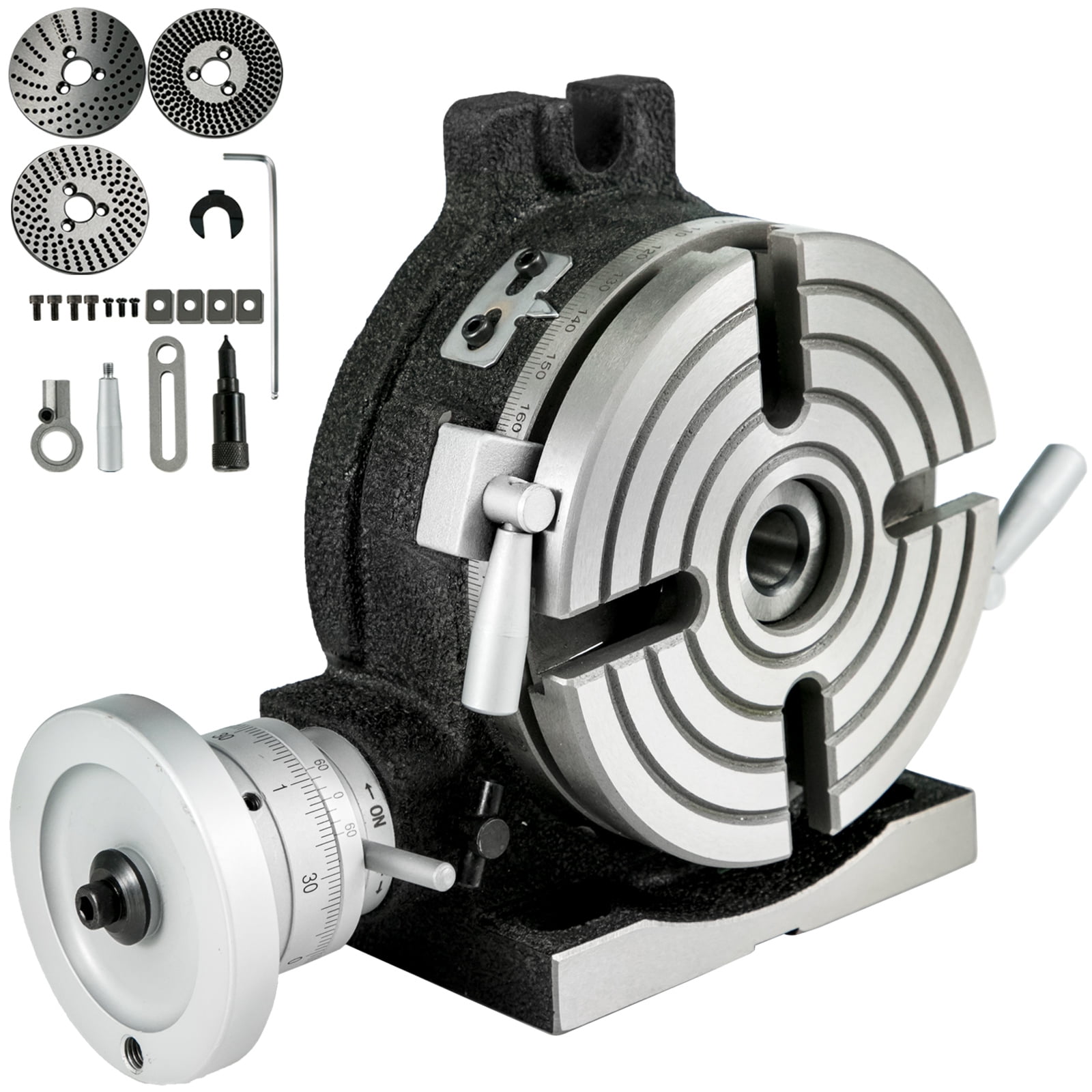
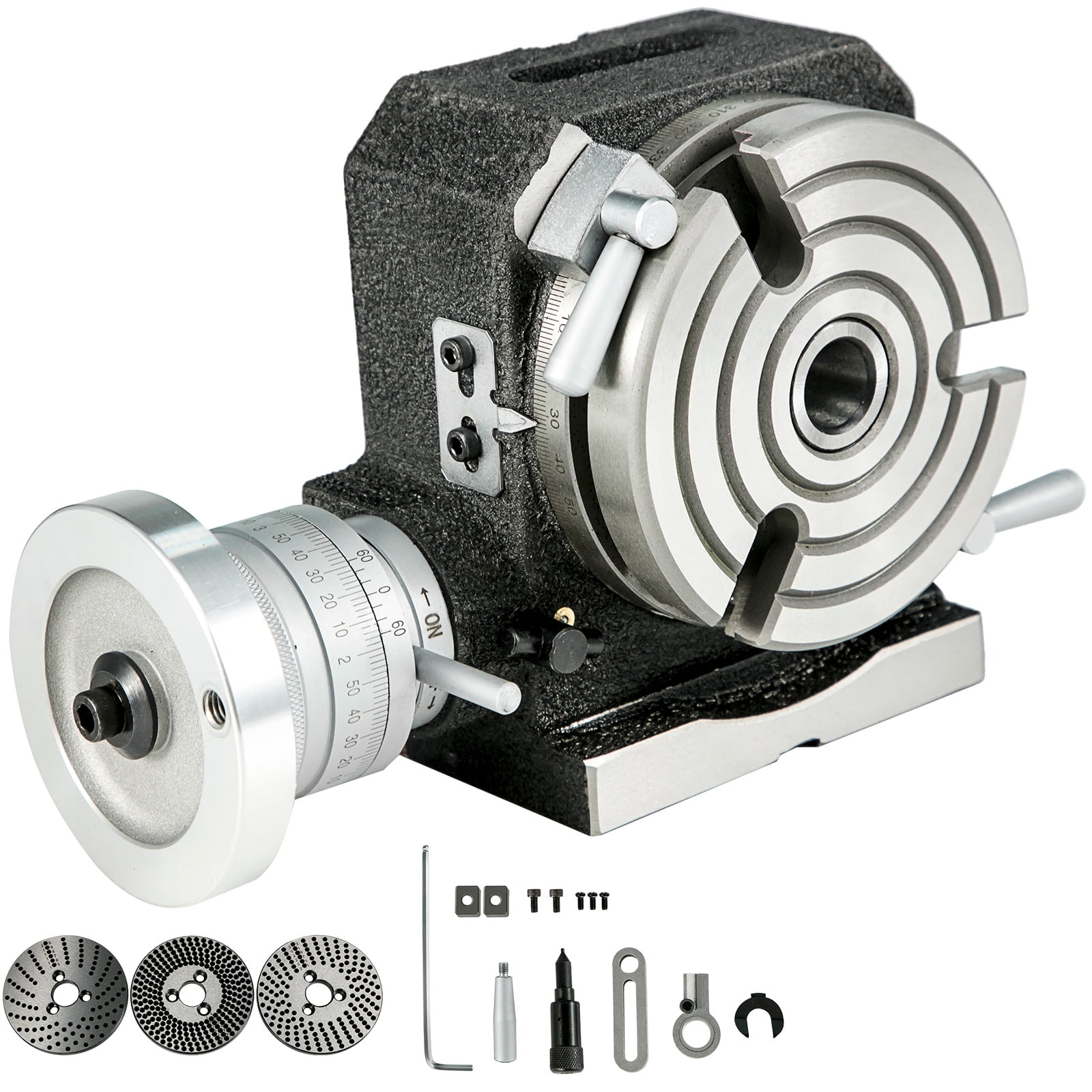
The mill rotary table is one of the main accessories of milling machine. As a precision work positioning device, it is widely used for indexing drilling, milling, circumferential cutting, boring, etc. The rotary turn table for milling machine is made from HT200 casting with high quality. It has already passed the ISO9001 quality system certification. They are are very popular on the market for their superior performance, excellent design and reasonable cost.
Both vertical and horizontal with two functions. Circle cutting, indexing drilling, milling and more complicated work are possible when the vertical position of the table is used together with the tail part.
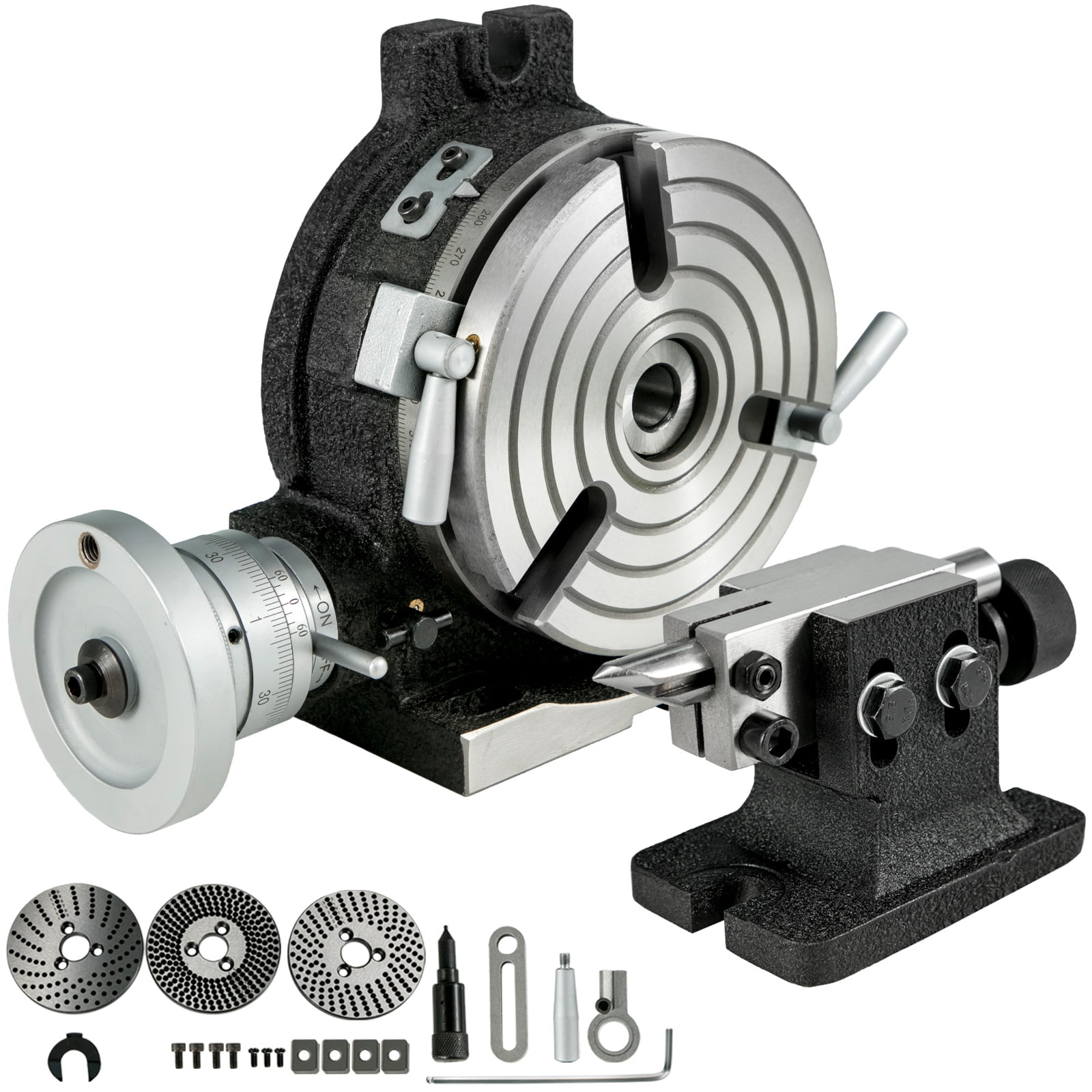
It works well. Functionally, it’s pretty great.It comes with some extras, but not much of an explanation. Because it can mount parallel or perpendicular, it lacks a way to clamp it to the table for parallel use. I had to machine a toe clamp to hold the other end. Thankfully, I have a mill. But, it’d have been so much easier to include one since it’s necessary.Otherwise, the 90 turns for 360 (1 for 4), works out pretty well for any angle divisible by four - 72, 60, 120, etc. I had to machine a way to attach my lathe chuck. Spent a half hour making the little piece I pictured… worked well for not using the dividing plates.Solid. Fairly precise. Works. But you’re going to have to make things to use it.
CAD and a ro"tab are overkill for that port. ( It"s just a lever. No cam or follower surface evident. ) I hate indicating in a ro"tab. Radius gages and freehand grinding to a scribe line are often economical and money making.
For more exact work and for a "machined" look I use the following method. Measure the hole spacings or for a one-off use a transfer punch. Radius gauge the outside curve or insert a wood plug in the hole and pickup the radius using dividers. Rough the blank on the band-saw then drill, bore, and ream the holes. Make a pin for each of the hole diameters. It"s useful if the pins have a tapped hole in the end for a hold-down clamp. Clamp a pin in a V in the soft jaws on the vise. Slip a washer then the part over the pin. Use big vise grips to hold and rotate the part on the pin. Mill radius using reverse spiral end-mill, sneaking up on the radius. ( This takes a touch as the part wants to bounce and grab. ) Don"t go past the tangent to the sides. Leaving the ends of the radius a little short from the tangent help to avoid grabbing and looks fine when you blend. It helps to mill in two sweeps starting from the end of the radius and milling into the center then flip the part and mill the other end. Now, to blend the sides into the radii you just mount the part, side up, in the mill vice and level the part so the radii on each end of the segment are even with each other. This does not have to be exact. Just eyeball it. Slide wedges under the part to take the downward milling force. Cut the side down till it blends with the radius. Repeat for the other sides.
This process has the potential to make very nice, milled, end radii that blend consistently into the sides. Having a good way to hold and control the part while pivoting on the pin is very important as is having a bolt and washer in the end of the pin to hold the part down. Works best on AL and thin parts. The big time waster is makings pivot pins so the procedure is suited to multiple part runs or for duplicate hole sizes on a part.

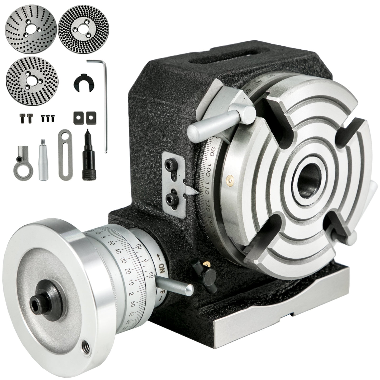
6" base adapter plate is ideal to use on 6" rotary tables of either 3 or 4 slots to mount either 4" , 5" 3-jaw ,6-jaw or 4-jaw self-centering lathe chucks.

Discussion on all milling machines vertical & horizontal, including but not limited to Bridgeports, Hardinge, South Bend, Clausing, Van Norman, including imports.
I have a Jet JTM-830 vertical mill with a 7-inch wide table. Would there be anything wrong with using a 10-inch rotary table? It would hang over a bit, but it seems like it would allow for easier clamping, and machine table movement would allow me to cover the whole table. I obviously don"t want one so large or heavy that it affects the machine, but on the other hand, a 6-inch rotary table seems like it would have too many limitations.
I have a 12" Van Norman rotary table (probably 125lbs+) I use on all our machines, from the Grizzly Millrite copy to the VN 22L. I wouldn"t LEAVE it bolted to the table of the Grizzly, especially run way over to one side, but if the knee won"t hold that up, it probably shouldn"t be called mill. Get a big "un.
18x72 L&S, Fosdick 3ft radial, Van Norman 2G bridgemill, Van Norman #12, K. O. Lee T&C grinder, Steptoe-Western 12X universal HS shaper, 16spd benchtop DP, Grob band filer, South Bend 10L
The 10" and 12" rotary table is fairly common in shops with standard Bridgeport mill types having a 9" table. The 10" should be adequate and a lot lighter than the 12"s. There are also 8" rotary tables. I doubt weight would be an issue for these smaller sizes.
Speaking of weight. The import RT"s are made quite a bit heavier than good domestic ones. That may be due to recycled materials not being as strong in thinner cross sections, less flex, less chance of failure in the casting process possibly. If you can, do a weight comparison between manufacturers you are looking at. As with a lot of the imports, they may be from the same factory, different label.
Your assessment is right on the money. Buy the largest table you are comfortable in handling. I use a 12" and wouldn"t want one any smaller. It"s just too damned hard to make acceptable setups on small tables. If it weren"t for the difficulty of handling the 15" Bridgeport table, I"d have bought that in place of the 12" one I own.
I"d have to admit that the majority of RT setups using toe clamps do eat up the outer 1"+ of the table surface. Thereby reducing the working envelope if no other means of work holding are available.
I hope to put up an I-beam trolly with an electric hoist to avoid lifting my 12" RT. I would not want to even think of lifting a 15" unit without a hoist system. LOL!
I did buy mine along with the dividing plates and tailstock, but the 12" diameter gets in the way for horizontal work. Fortunately I have a spin index, super spacer and gear indexing head to handle some of those areas. Since I have CNC capability now, it sure has spoiled my need for a RT as much.
That"s the one place size can work against you. I have the right angle plate for my Bridgeport, and it"s all I can do to put the rotary table on the mill when it"s mounted to the plate. A lifting device certainly wouldn"t be a bad idea, especially now that I"m older and don"t have the physical strength necessary to handle the table. I guess my advice might be tempered with the comment that it depends on how you"d use your table--------the smaller tables can be easier to use when doing horizontal work, and don"t eat up spindle clearance quite as much.
You could always buy a smaller table and then add an aluminum sub table to it to make it larger. My table is 8" and I plan to make a 12" table top 1" thick. Then you can drill and tap it for clamps or whatever you prefer.
You could always buy a smaller table and then add an aluminum sub table to it to make it larger. My table is 8" and I plan to make a 12" table top 1" thick. Then you can drill and tap it for clamps or whatever you prefer.
That"s an excellent way to extend any rotary table. I have a plate that is about 16" diameter that pins to the center hole of my table for quick setup. I also drilled and counterbored the mounting holes so nothing is above the surface when it"s installed. As you suggest, it"s easy to drill and tap holes as necessary.
Interesting responses. Thanks, gentlemen. I like the idea of the add-on plate, and I just happen to have a nice piece of ground aluminum tooling plate that should work in my non-production facility.
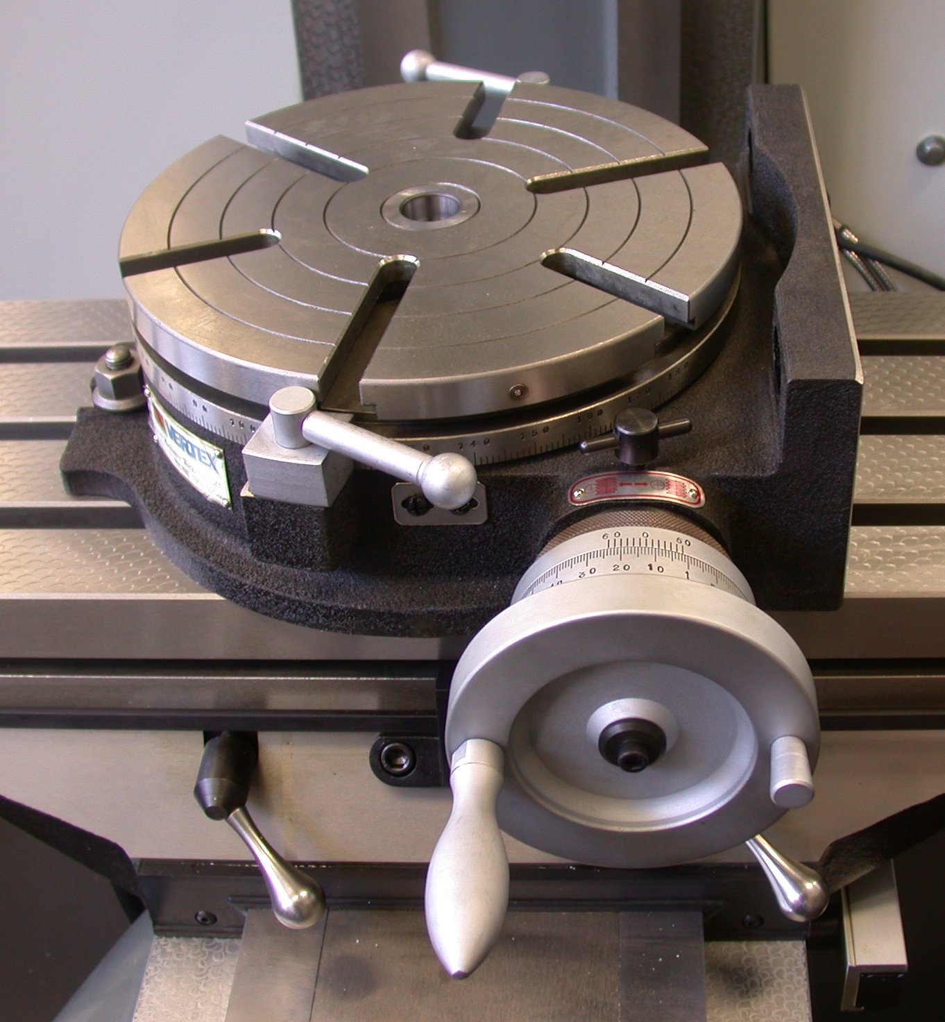
This is how that can work. This operation is milling radiused cheek horn slots (to 11"R) on locomotive axleboxes. The "plank" is a piece of 3/4" steel plate picked up as scrap and surface prepped. The DTI at right is placed so as to indicate rise of table and therefore exact depth of cut.
The rotary table is a restored 9" Troyke (ca 1949), a grimey lump picked up for peanuts on eBay but which turned out to be virtually unused under the grunge. I"m not sure of the weight of this but it"s about the heaviest table I"d want to lug around the workshop and keep off the machine and mount it each time I needed to use it.
Wo-ho. THAT is the way to make those large radious slots. ! ! ! ! I was going to tripple cut and blend with a file. What a neat trick. On the small work, flex wont be a big problem. Thanks . Thats why I lurk on this board.
Big Dave, former Millwright, Electrician, Environmental conditioning, and back yard Fixxit guy. Now retired, persuing boats, trains, and broken relics.

The Vertex is different from the others ... you have to buy a separate lathe-style chuck with an MT2 or MT3 arbor sticking out the back of the chuck. The main part has a MT2 or MT3 hole, and the body rotates on a horizontal axis to tilt. You don"t have to use the usual lathe-type chuck on it. For small work you can use a Jacobs chuck with arbor. I don"t think you can do rotation about 2 axes, just one; but I could be wrong. I have seen one at the tool store I go to and they have still not sold it after a couple of years so perhaps it is not as useful as I think but it sure does look nice.
As for the term "hinge", I made that up. The one I am thinking of is still called a rotary table; there are two parts ... the rotary table, and then the base. The two are connected on one side by the hinges (just two tabs with holes, a rod, and the horizontal hole in the base that the rod goes through). The tab parts fit over the edges of the base and the rod slides through the tab holes and the horizontal hole in the base.
Even with a rotary table that is not hinged, you can mount it vertically and in that position you might call it a dividing head because you can usually buy a tailstock for it, and, for certain ones the dividing plates.
I forgot to tell you that I had this. Again, I knew I would need one eventually, so I bought one even before I met you !! Have only started to use it.
The easy efficient way to convey molds for polyurethane molding lines Simplify your molding line operations with the efficiency and dependability of Rotary Tables from Polycraft/PUF Tables for both smaller and heavier mold operations The Turn Table, is ideal for small to mid-sized mold applications. The Turn Table comes manualread more...
Available with us is a wide variety of Rotary Tables that are cast out of alloy cast iron at our advanced manufacturing department. Offered in various specifications, these are utilized for performing division of work pieces. Moreover, our clients can also avail these on customization to meet their specific requirements generalread more...
HeatLine is EFD Induction’s family of systems for melting and forging applications. A comprehensive range, HeatLine systems feature serial and/or parallel compensated induction power sources for a wide range of output powers and frequencies.
Near To Guestline Hotel, Bengaluru Plot No.16C & D, Hosur Road, Kiadb Industrial Estate, Attibele, Near To Guestline Hotel, Bengaluru - 562107, Dist. Bengaluru, Karnataka
These G codes are used to specify circular motion. Two axes are necessary to complete circular motion and the correct plane, G17-G19, must be used. There are two methods of commanding a G02 or G03, the first is using the I, J, K addresses and the second is using the R address.
I, J and K address are used to locate the arc center in relation to the start point. In other words, the I, J, K addresses are the distances from the starting point to the center of the circle. Only the I, J, or K specific to the selected plane are allowed (G17 uses IJ, G18 uses IK and G19 uses JK). The X, Y, and Z commands specify the end point of the arc. If the X, Y, and Z location for the selected plane is not specified, the endpoint of the arc is the same as the starting point for that axis.
To cut a full circle the I, J, K addresses must be used; using an R address will not work. To cut a full circle, do not specify an ending point (X, Y, and Z ); program I, J, or K to define the center of the circle. For example:
The R-value defines the distance from the starting point to the center of the circle. Use a positive R-value for radii of 180 or less, and a negative R-value for radii more than 180.
Thread milling uses a standard G02 or G03 move to create the circular move in X-Y, then adds a Z move on the same block to create the thread pitch. This generates one turn of the thread;
Use a G03 to cut I.D. threads or a G02 to cut O.D. threads. An I.D. right hand thread will move up in the Z-Axis by the amount of one thread pitch. An O.D. right hand thread will move down in the Z-Axis by the amount of one thread pitch. PITCH = 1/Threads per inch (Example - 1.0 divided by 8 TPI = .125)
The next step is to program a complete circle (G02 or G03) with a Z-Axis command of the amount of one full pitch of the thread (this is called Helical Interpolation).
You cannot turn cutter compensation off or on during an arc movement. You must program a linear move, either in the X or Y Axis, to move the tool to and from the diameter to cut. This move will be the maximum compensation amount that you can adjust.
Outside Diameter (O.D.) Thread MillingO.D. Thread Milling Example, 2.0 diameter post x 16 TPI: [1] Tool Path [2] Rapid Positioning, Turn on and off cutter compensation, [3] Start Position, [4] Arc with Z.
This program is for a 1.0" diameter hole with a cutter diameter of 0.500" and a thread pitch of 0.125 (8TPI). This program positions itself in Absolute G90 and then switches to G91 Incremental mode on line N7.
Helical (spiral) motion is possible with G02 or G03 by programming the linear axis that is not in the selected plane. This third axis will be moved along the specified axis in a linear manner, while the other two axes will be moved in the circular motion. The speed of each axis will be controlled so that the helical rate matches the programmed feedrate.
Rotary Milling Tableoffered comes in quality metal construction finish and is made available at competitive prices. These full size milling tables come developed using high strength resin sand casting as well as feature 3-axis line rail and high speed spindle unit. Some of its features include separate hand wheel support; turntable style tool magazine; pneumatic broach system; adjustment support for shim and screw; automatic intermittent lubrication.
A rotary desk is the revolving plate at the rig"s drill ground that turns the drill string in a clockwise course. The rotary table surrounds the 4 or six-sided kelly bushing and kelly force to which the drill string is hooked up, moving the strength from the rig"s force device to the drill string and bit.
The rotary table hyperlinks the rig"s strength deliver to the drill string, it may be described as a capture. most rigs have a rotary desk due to the fact the top mover for the drill string, however, top strength structures that permit continuous rotation of the drill string have changed the rotary desk, the kelly bushing and the kelly strain in a few rigs, because of changes in trenchless construction requirements.
The rotary force table is familiar in pinnacle-pressure rigs, that is, those who have their pressure motor at the top of the rig. Drill string sections are first linked to the bottom hole assembly. As drill string sections bypass into the bore, extra sections of drill string are connected to the pinnacle strain motor and to sections inside the bore, constructing the drill string from the top. the ones sections of drill string screw collectively the usage of a clockwise movement. The rotary desk -- which turns clockwise -- is used to tighten the segments of the drill string.

The milling machine is the workhorse of the machine shop. In essence, a vertical mill is like a drill press, except it is fitted with sturdy bearings capable of handling side as well as end loads. Normally up to 85% of machining jobs will require a mill rather than a lathe. Unlike a lathe that spins the material, a mill holds the material firmly while the part is moved across a spinning tool or the spinning tool is brought down into the part. The part is moved very accurately by means of a table that can be controlled in two directions (X-axis = left/right and Y-axis=in/out). The third axis is provided by a vertical spindle (Z-axis) that moves up and down. The mill can be used for milling slots, holes or pockets, drilling, profiling, boring, and surfacing. Most milling is done using “end mills” that look much like a drill bit except they are capable of cutting on the sides as well as on the end. They are held in an end mill holder and can cut slots, pockets or flat surfaces. A drill chuck can be used for holding drill bits. For larger surfaces, a “fly cutter” is used. It is a single-pointed tool that spins in a large arc and is brought across the surface of the part to flatten it.
The 4th axis of a milling machine is the rotary axis (called the A-axis) provided by an optional rotary table. A mill with a rotary table is a powerful combination. Technically, a mill with a rotary table is the minimum combination of tooling required to reproduce itself: that is, make another mill and rotary table.
Spindle—The spindle is inside the headstock and is driven with a belt running from the motor pulley to a pulley on the rear end of the spindle shaft. The nose of the spindle is threaded on the outside to receive chucks and tapered on the inside to receive other accessories.
Leadscrew—The threaded screws that move the table left/right and in/out as well as the vertical axis up and down. They are driven by handwheels marked in .001” or .01 mm increments.
Leadscrew Locking Lever—Located on the back side of the vertical column, this locking lever locks against the saddle nut to prevent unwanted movement of the Z-axis during machining operations. Manual machines are fitted with a standard on/off locking lever. CNC machines are fitted with an adjustable locking lever that can be used to control backlash in the Z-axis. This function is available as an option on any manual mill as well. (P/N 4017U inch or 4117U metric)
Gibs—Tapered plastic gibs are used on each dovetailed axis to take up wear as it occurs. They are slightly wedge-shaped. As side-to-side “slop” develops on an axis, the gib lock is loosened and the gib is pushed a little further into the gap, taking up the play. These allow the machine to always be kept as tight as the operator desires. If or when they wear out, they are very inexpensive to replace.
Drawbolt—Goes through the hole in the spindle to draw chucks and other accessories into the headstock taper inside the spindle. A special washer locates in on center in the spindle hole.
#1 Morse Arbor—The arbor screws into the back of the drill chuck so it can be used in the headstock. It is held in place in the #1 Morse taper with the drawbolt.
X-axis Locking Screw—A screw that goes through the barrel lock on the front of the saddle to lock the table in place during machining operations where movement is not required or desired.
Backlash Locks—The lock works like tightening two nuts against each other on a threaded shaft to reduce play in the threads. Backlash is the pause in travel when changing the direction of rotation of any threaded crew. Because both sides of the thread don’t rub on the nut at the same time (they would quickly wear out), one surface is pulling or pushing the nut when the screw is turned. When you stop and change directions, the screw turns a slight amount while the thread picks up the other side and begins to move the nut in the other direction. The looser the fit of the threads, the more “backlash” occurs. In essence, it is the amount you can turn the handwheel in the reverse direction before movement occurs on an axis. An adjustment is provided on the X- and Y-axes to reduce the leadscrew backlash. Backlash is not a “fault” of a machine; it is simply a physical reality that must be taken into account when machining. You adjust to a known or acceptable amount using the locks and then remove it from the machining operation by always approaching your cut from the same direction with the backlash already eliminated before the cut begins.
Alignment Key—A precision ground key that fits in a slot in the column saddle to keep the headstock aligned straight up and down. A second slot is also provided to locate the headstock at 90° for horizontal milling. Removing this key and rotating the headstock allows bevels to be cut at any angle. An approximate angle scale is laser-engraved into the saddle for reference.
Headstock Spacer Block—Moves the headstock 1.25” further out from the saddle to increase the “throat” distance (distance between cutter and column). It is optional on 5000-series mills, standard on 5400-series mills, and not needed on 2000-series mills because the ram can be used to adjust this distance.
2-position Pulley—The normal (rear) position gears the motor down about 2:1 for a maximum speed of about 2800 RPM. The “High Torque” position (closest to the headstock) gears it about 4:1 for lower speed but more torque when needed for heavy cuts.
Column Ram—On the 2000-series mills, a “ram” is added that allows the entire column to be moved in and out and swung from side to side. It is designed based on the movements of the machine shop workhorse—the Bridgeport® mill.
Rotary Column Attachment—This function allows the vertical column to be rotated from side to side to do angled milling or drilling. It is included in the design of the 2000-series mills or can be added as an option (P/N 3700) to 5000/5400-series mills.
Adjustable “Zero” Handwheels—On base model machines, plain handwheels are used. They are laser engraved with 50 marks (inch) or 100 marks (metric) and numbers for reference. Adjustable zero handwheels allow you to stop at any given point, loosen a knurled wheel in the center of the handwheel and rotate the laser engraved collar back to the zero mark before starting the next cut without moving the position of the handwheel. This means each time you are starting from zero rather than from a random number, making your depth and cut calculations easier. This eventually means fewer mistakes. 4400- and 4500-series lathes and 5400- and 2000-series mills include these upgraded handwheels as standard equipment.
DRO—Stands for “Digital Readout”. Digital readouts incorporate an electronic box with a screen that reads out numbers rather than looking at the graduations on the handwheels to determine movement. It offers two advantages: For those with poor eyesight, it is easier to read than the little marks on the handwheel, and 2) It keeps track of accumulated distance so you don’t have to count handwheel revolutions when making longer movements. This helps eliminate a common source of errors. Any Sherline lathe or mill can be ordered fitted with DRO or it can be added later. Also incorporated in the readout is a sensor and RPM indicator for the spindle to eliminate guesswork regarding spindle speed.
CNC—Stands for “Computer Numeric Control.” Instead of you turning the handwheels, a computer determines the speed and distance and drives DC motors called “stepper motors” or “servos” to move the lathe for you. Any Sherline machine can be ordered ready for the application of CNC or as a complete CNC system with steppers, controller, computer, software and everything. CNC can also be fitted at a later date to any Sherline lathe or mill.
4th Axis—In milling, in addition to the X-, Y- and Z-axis, the 4th axis is called the A-axis or rotary axis and is provided by an optional rotary table. Sherline offers manual (P/N 3700) or CNC (P/N 8700 or 8730) rotary tables.
End Mills—They look like drill bits but are sharpened on the sides as well as the ends. Held in an end mill holder, they are used to cut slots, pockets or surfaces. End mills are normally flat but “ball end” mills are also available that have a round end for leaving a radius in the corner of a pocket or a round-bottomed slot. End mills can have two, three or four flutes (spiral cuts) in the sides. Generally, fewer flutes are better for softer materials like aluminum because they don’t clog as easily, while more flutes (and slower cutting speeds) are better for steels that don’t allow as aggressive a cut and produce fewer chips per cut.
Fly Cutter—A mandrill holds a 1/4” square shank HSS or Carbide cutter and spins it in a large circle (about 1-1.5”). The part is moved under the cutter which puts a nice, flat surface on the part. Each successive cut overlaps the previous by about 1/3 of the cut until the surface is done.
Mill Vise—A small vise that is clamped to the mill table and holds parts for milling. It is different from the more common drill press vise in that it tightens with a pull-down function that helps hold the part down as well as in to counter the forces of milling. It is also accurately machined so it can be aligned in the machine for accurate cuts.
Hold-down Set—A series of adjustable clamps that are used to hold parts to the mill table for milling. They can be used on large or uneven parts like castings.
Boring Head—Rotated in the headstock, the boring head holds a sharpened tool that rotates off center to scribe a circle. It is lowered into the bore of a hole to enlarge the hole to a given size. A fine adjustment on the boring head allows the cutter to be moved out a little at a time to enlarge the circle of the cut. It is used when a very accurate hole is needed, like on the cylinder of an engine or when a large drill of the needed size is not available or practical. With the boring head, you can make accurate holes up to 1.75” in diameter on a small mill.

Compact precision CNC rotary table, suitable for single part or small batch production in precision engineering. A horizontal or vertical assembly is possible. You can not buy a better quality!
It is suitable as 4th axis on engraving and milling machines for engraving, lasering, drilling, grooving, milling or for use on a tool or surface grinding machine. Square, hexagonal, gear milling of any pitch or 3D machining is possible.
Technical data: - center distance 1500 mm- center height 400 mm- max. machining diameter FI 400 mm- motor power 4,0 kW- voltage 400 V / 50 Hz- spindle speed 3000 rpm- number of controlled axes 3- guide linear guides and ball screw- control MACH3 + software- pneumatic workpiece clamping- V-shape steel- milling spindle for flat engraving- compressed air supply 6 bar- dimensions L=2700, W=1400, H=1750 mm- net weight 1800 kg
Kehren RIW9 CNC rotary table surface grinding machine Max workpiece diameter 900mm x 500mm height complete with internal grinding spindle it can be inspected in our warehouse in Gussago BS Italy Mimu Machine Tools

A rotary table is a mechanical device on a drilling rig that provides clockwise (as viewed from above) rotational force to the drill string to facilitate the process of drilling a borehole. Rotary speed is the number of times the rotary table makes one full revolution in one minute (rpm).
Quote from video: I"m gonna use the spindle with a dial indicator to Center it up once I"m on center I"m gonna clamp down and then. I can offset the milling machines table by the proper.
A rotary engine is an internal combustion engine that separates an engine’s four jobs — intake, compression, combustion, and exhaust — into four individual parts within the overall engine housing. The rotor moves from chamber to chamber, expanding and contracting gas.
There are two groups of big rotary drilling: (1) rotary crushing by high-point loading to the rock from three cones, as shown in Fig. 7.7a, and (2) rotary cutting by shear force from drag bits, as shown in Fig.
A conventional rotary rig or rotary table rig or kelly drive rig is a drilling rig where the rotation of the drill string and bit is applied from a rotary table on the rig floor.
A rotary table is a disc-shaped metalworking device used to obtain precise workpiece positioning. It enables a metalworker to cut or drill a workpiece at precise intervals around a vertically or horizontally fixed axis.
Quote from video: That"s how it"s much better so just install it in a collet. Okay then run run your tool down until it goes into the bore of the rotary. Table. All the way down until it starts to Snug.
A rotary steerable system (RSS) is a form of drilling technology used in directional drilling. It employs the use of specialized downhole equipment to replace conventional directional tools such as mud motors.
A rotary joint, also referred to as a rotary union or rotating union, is a rotary sealing device that connects rotating equipment to fixed piping for the transfer of steam, water, thermal oil, coolant, hydraulic oil, air, and other media.
BALL DRIVE TABLE. Unlike the worm drive, these tables have zero backlash and maintenance, higher speed indexing, higher accuracy, and higher rigidity. …
A rotary indexing table is specifically designed to make repetitive moves around a platform. Essentially, they are highly precise work-positioning devices that index parts to be worked or machined in multiple operations.
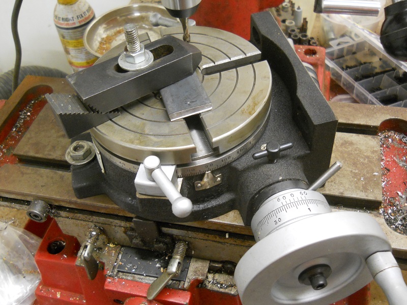
With the face horizontal, it has been used to mill curved slots, and could be used equally well to put a radius on the end of a workpiece. If you want to choose between one or the other, the rotary table can be set at any angle, but a dividing head cannot.
A milling table is a part of a standard milling machine. The table is an important part of the machine’s function and is featured on every complete milling machine. The milling table is where a worker sets his work piece in order to mill it with the attached milling head.
Indexing is an operation of dividing a periphery of a cylindrical workpiece into equal number of divisions by the help of index crank and index plate. A manual indexing head includes a hand crank. Rotating the hand crank in turn rotates the spindle and therefore the workpiece.
The workpiece is held on a worktable of the machine. The table movement controls the feed of the workpiece against the rotating cutter. This cutter is fixed on a spindle or arbor which revolves at desired speed.
There are five roll systems in a flour mill: break, sizing, midds (for middlings), low grade, and residue. In the break system, the kernel is opened, the bran flattened and the endosperm broken into large chunks.

You say you have a rotary table. Use it. Make a setup similar to the photos in RichR"s post. Do conventional milling, which we would find in that last photo where the end mill rotates to the right, and the table would be rotated in a counter clockwise direction, so that the cutter and work are moving in opposite directions. For a plate 3/8 thick I suggest going with a four flute end mill. It will give a fine finish and have less chip load per tooth than a two flute.

The TR160 5 Axis Rotary Tables, manufactured by Haas, consist of dual axis Trunnion rotary table that is capable of tilting up to 160 mm. It also has a scale assessment ...
The TR210 is HAAS"S rotary table developed and configured to be integrated with HAAS"S mills 4th and 5th axis drivers to provide complete and optimum operation. It has a diameter of 210 mm made from trunnion ...
... space with high load capacity. The individual rotary tables are equipped with Harmonic Drive units, which ensure high moment load capacities and high concentricity and axial runout accuracies.
The work table is graduated 360 degrees around its circumference and is driven by a precision Worm and Gear providing a 90:1 reduction ratio. One turn of the Handle moves the Table through 4 degrees. ...
... Tilt-Yaw (A/B) two-axis rotary assembly provides high-speed machining capabilities for complex 3D part geometries. The precision-aligned system allows accurate positioning on a hemispherical surface. ...
... ) MDR two-axis rotary assembly provides high-speed machining capabilities for complex 3D part geometries. The precision-aligned system allows accurate positioning on a hemispherical surface. Uses cost-effective ...
... ) MDR two-axis rotary assembly provides high-speed machining capabilities for complex 3D part geometries. The precision-aligned system allows accurate positioning on a hemispherical surface. Uses cost-effective ...
Our FÖRSTER swivel welding tables offer maximum working comfort for all-round welding of complex assemblies. Ideal for all tasks due to a variable arrangement of our patented T-slot system.
The hydrostatic rotary tables from ZOLLERN impress with their durability and a high concentricity and axial runout accuracy. Thanks to the ZOLLERN bearing clearance compensator, the optimal pocket pressure ...
... the table is the rotation, the user may require the rotary table for drilling operations and milling. Using the servo drives in conjunction with the machine CNC control ...
With DirectIndustry you can: Find the product, subcontractor or service provider you need | Find a nearby distributor or reseller| Contact the manufacturer to get a quote or a price | Examine product characteristics and technical specifications for major brands | View PDF catalogues and other online documentation


 8613371530291