
milling a radius on a rotary table quotation

CAD and a ro"tab are overkill for that port. ( It"s just a lever. No cam or follower surface evident. ) I hate indicating in a ro"tab. Radius gages and freehand grinding to a scribe line are often economical and money making.
For more exact work and for a "machined" look I use the following method. Measure the hole spacings or for a one-off use a transfer punch. Radius gauge the outside curve or insert a wood plug in the hole and pickup the radius using dividers. Rough the blank on the band-saw then drill, bore, and ream the holes. Make a pin for each of the hole diameters. It"s useful if the pins have a tapped hole in the end for a hold-down clamp. Clamp a pin in a V in the soft jaws on the vise. Slip a washer then the part over the pin. Use big vise grips to hold and rotate the part on the pin. Mill radius using reverse spiral end-mill, sneaking up on the radius. ( This takes a touch as the part wants to bounce and grab. ) Don"t go past the tangent to the sides. Leaving the ends of the radius a little short from the tangent help to avoid grabbing and looks fine when you blend. It helps to mill in two sweeps starting from the end of the radius and milling into the center then flip the part and mill the other end. Now, to blend the sides into the radii you just mount the part, side up, in the mill vice and level the part so the radii on each end of the segment are even with each other. This does not have to be exact. Just eyeball it. Slide wedges under the part to take the downward milling force. Cut the side down till it blends with the radius. Repeat for the other sides.
This process has the potential to make very nice, milled, end radii that blend consistently into the sides. Having a good way to hold and control the part while pivoting on the pin is very important as is having a bolt and washer in the end of the pin to hold the part down. Works best on AL and thin parts. The big time waster is makings pivot pins so the procedure is suited to multiple part runs or for duplicate hole sizes on a part.
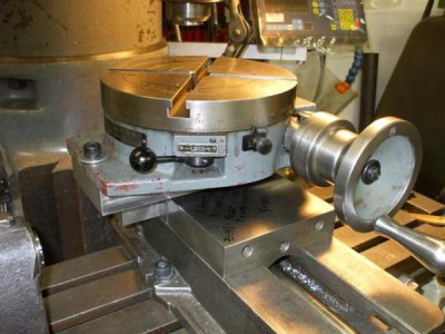
I have a 12" Enco horizontal/vertical rotary table which I keep mounted permanently on my old mill/drill. It has a 1" diameter bore and I made an adapter for my 4" scrolling chuck. A threaded backplate and stud keep it securely fastened. To center the table, I put a scrap piece in the chuck and "turn" a cylinder with an end mill. I then use and edge finder to accurately align the true center of of the rotary table with the spindle axis. A test indicator mounted on the spindle would also work well. The mill has a DRO
I use the table to cut arcs. If the part has a single arc, I position the part so the center of the arc is on the table axis. All the linear features can be made by a combination of x, y and table moves. Just make sure to record the home position before moving and axis! A DRO really shines for this.
Lastly, I had done some very precise pseudo four axis machining by setting the table in a vertical position with the axis parallel with the x axis. The table was centered in the y direction by cutting four square faces, making a cut and rotating 90 degrees and repeating until all four faces were cut. A micrometer was used to measure the resulting square. The end mill position is half the measured thickness. I found the x position by facing the y-z face and locating the edge with a sharp point and a 50x microscope.
A custom tool setter system datum was made from a silver alloy relay contact mounted on the table and wired to an LED indicator. This was because one of the tools used was a .008" micro drill and another was a 0000 center drill. With setup, I could do tool changes very accurately.
Because I was doing some rather complex machining steps, I found it useful to choreograph the machining in an Excel spreadsheet, listing the operation, the face worked , the tool used, the coordinates, and the DRO setting. An example is attached.

This website is using a security service to protect itself from online attacks. The action you just performed triggered the security solution. There are several actions that could trigger this block including submitting a certain word or phrase, a SQL command or malformed data.

2. Depending on the type of mill, round column or knee, provide enough head space to indicate the center of the rotary table and still get a cutter to the workpiece.
3. Mount your part. If the part is irregular shaped sometimes it"s easier to make up a mounting plate to fasten the part to. This way you can move the part to center and then clamp the plate in place.
6. For a part similar to what you"re showing you will also need to have a layout line that runs across the piece. Once you have the part on center square up the layout line by rotating the table as you move from end to end on the layout line. (with a wiggler)
9. Move one axis off center and then move the table back toward the part until the cutter starts to cut. Before you cut you should know what calculated degree of angle you will need to stop the radius at. This will be the blend point between the radius and the straight wall.
10. Start cutting your radius. Generally I stay about 1/2 degree away from my tangent point until I get the radius to where I want it. This will prevent the cutter from digging in and leaving a mark where the tangent point is. After you have the radius milled rotate the table to the appropriate angle and mill the straight sides. There will be a small amount of stock where you stayed shy of the angle when cutting the radius.
11. Now for your final cut, rotate the table so that your straight cut will be a climb cut. Take a finish pass along the straight wall until you axis dial reads -0-. Rotate the table the required amount until you get to the other tangent angle, lock the rotary table and then make your final straight cut.
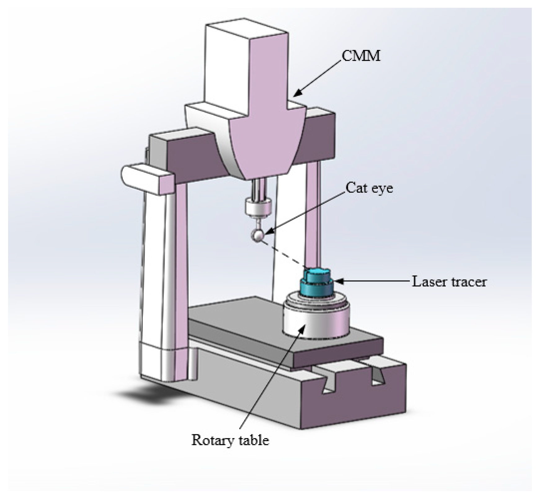
The stage includes an optical rotary encoder with a digital TTL output signal. After 400x interpolation, the resolution of one encoder count = 0.07 arc-sec (0.33 µrad). Very fine encoder resolution is necessary to enable smooth velocity control by the servo system.
Stiffness measurements were taken by loading the bearing in different orientations and measuring displacement.Measured Axial Stiffness @ 80psi: 875 N/µmMeasured Radial Stiffness @ 80psi: 133 N/µmMeasured Tilt Stiffness @ 80psi: 14 Nm/µrad
Of utmost importance to this application was the very low error motion of the air bearing. Measurements were taken using a master ball and a capacitance probe. The master ball was mounted 50mm above the air bearing tabletop. Total radial runout error motion measured was less than +/-25 nanometers.

TitleRogers" Drawing and Design: An Educational Treatise Relating to Linear Drawing, Machine Design, Working Drawings, Transmission Methods, Steam, Electrical and Metal Working Machines and Parts ...
·Typical use cases include machining the flutes of a milling cutter, cutting the teeth of a gear, milling curved slots, or drilling a bolt hole circle around the circumference of a part.
The TR160 5 Axis Rotary Tables, manufactured by Haas, consist of dual axis Trunnion rotary table that is capable of tilting up to 160 mm. It also has a scale assessment ...
The TR210 is HAAS"S rotary table developed and configured to be integrated with HAAS"S mills 4th and 5th axis drivers to provide complete and optimum operation. It has a diameter of 210 mm made from trunnion ...
... space with high load capacity. The individual rotary tables are equipped with Harmonic Drive units, which ensure high moment load capacities and high concentricity and axial runout accuracies.
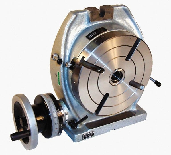
The work table is graduated 360 degrees around its circumference and is driven by a precision Worm and Gear providing a 90:1 reduction ratio. One turn of the Handle moves the Table through 4 degrees. ...
... Tilt-Yaw (A/B) two-axis rotary assembly provides high-speed machining capabilities for complex 3D part geometries. The precision-aligned system allows accurate positioning on a hemispherical surface. ...
... ) MDR two-axis rotary assembly provides high-speed machining capabilities for complex 3D part geometries. The precision-aligned system allows accurate positioning on a hemispherical surface. Uses cost-effective ...
... ) MDR two-axis rotary assembly provides high-speed machining capabilities for complex 3D part geometries. The precision-aligned system allows accurate positioning on a hemispherical surface. Uses cost-effective ...
Our FÖRSTER swivel welding tables offer maximum working comfort for all-round welding of complex assemblies. Ideal for all tasks due to a variable arrangement of our patented T-slot system.
The hydrostatic rotary tables from ZOLLERN impress with their durability and a high concentricity and axial runout accuracy. Thanks to the ZOLLERN bearing clearance compensator, the optimal pocket pressure ...
... the table is the rotation, the user may require the rotary table for drilling operations and milling. Using the servo drives in conjunction with the machine CNC control ...
With DirectIndustry you can: Find the product, subcontractor or service provider you need | Find a nearby distributor or reseller| Contact the manufacturer to get a quote or a price | Examine product characteristics and technical specifications for major brands | View PDF catalogues and other online documentation

A rotary table is a mechanical device on a drilling rig that provides clockwise (as viewed from above) rotational force to the drill string to facilitate the process of drilling a borehole. Rotary speed is the number of times the rotary table makes one full revolution in one minute (rpm).
Quote from video: I"m gonna use the spindle with a dial indicator to Center it up once I"m on center I"m gonna clamp down and then. I can offset the milling machines table by the proper.
A rotary engine is an internal combustion engine that separates an engine’s four jobs — intake, compression, combustion, and exhaust — into four individual parts within the overall engine housing. The rotor moves from chamber to chamber, expanding and contracting gas.
There are two groups of big rotary drilling: (1) rotary crushing by high-point loading to the rock from three cones, as shown in Fig. 7.7a, and (2) rotary cutting by shear force from drag bits, as shown in Fig.
A conventional rotary rig or rotary table rig or kelly drive rig is a drilling rig where the rotation of the drill string and bit is applied from a rotary table on the rig floor.
A rotary table is a disc-shaped metalworking device used to obtain precise workpiece positioning. It enables a metalworker to cut or drill a workpiece at precise intervals around a vertically or horizontally fixed axis.
Quote from video: That"s how it"s much better so just install it in a collet. Okay then run run your tool down until it goes into the bore of the rotary. Table. All the way down until it starts to Snug.
A rotary steerable system (RSS) is a form of drilling technology used in directional drilling. It employs the use of specialized downhole equipment to replace conventional directional tools such as mud motors.
A rotary joint, also referred to as a rotary union or rotating union, is a rotary sealing device that connects rotating equipment to fixed piping for the transfer of steam, water, thermal oil, coolant, hydraulic oil, air, and other media.
BALL DRIVE TABLE. Unlike the worm drive, these tables have zero backlash and maintenance, higher speed indexing, higher accuracy, and higher rigidity. …
A rotary indexing table is specifically designed to make repetitive moves around a platform. Essentially, they are highly precise work-positioning devices that index parts to be worked or machined in multiple operations.
With the face horizontal, it has been used to mill curved slots, and could be used equally well to put a radius on the end of a workpiece. If you want to choose between one or the other, the rotary table can be set at any angle, but a dividing head cannot.
A milling table is a part of a standard milling machine. The table is an important part of the machine’s function and is featured on every complete milling machine. The milling table is where a worker sets his work piece in order to mill it with the attached milling head.
Indexing is an operation of dividing a periphery of a cylindrical workpiece into equal number of divisions by the help of index crank and index plate. A manual indexing head includes a hand crank. Rotating the hand crank in turn rotates the spindle and therefore the workpiece.
The workpiece is held on a worktable of the machine. The table movement controls the feed of the workpiece against the rotating cutter. This cutter is fixed on a spindle or arbor which revolves at desired speed.
There are five roll systems in a flour mill: break, sizing, midds (for middlings), low grade, and residue. In the break system, the kernel is opened, the bran flattened and the endosperm broken into large chunks.

With proper selection and integration of high-performance brushless DC servo motors ABTech’s air bearing rotary tables provide ultra-smooth and precise rotary motion. With high torque, high performance motor drives, our motion experts will gather your specific requirements and work closely with our motor suppliers to create/select a motor drive that suits your specific application. Whether you need sub-micron position accuracy with minimal settle time and stringent following error specifications, high-speed constant motion, or a combination of both there is an ABTech rotary table that will meet your needs.
The motor drives are designed to accommodate a wide range of precision motion applications such as optical metrology; circular geometry gages; and micro machining with ultra-precision scanning, velocity control, speed regulation and precision indexing.
ABTech’s modular design approach facilitates multiple system configurations to optimize the price-for-performance required in your application. This approach allows the user to define the level of control desired for the most cost-effective solution. Our complete engineering services allow us to respond quickly to provide a solution to your O.E.M. requirements for ultra-precision rotary motion.

It"s a while since I"ve done this but as far as I remember, for the circular piece the process is the same as centering in a four jaw chuck - treating the rotating table as a chuck. I suppose it depends on your clamping mechanism as to how easy this is. A hinged DTI holder so you can lift the DTI out of the way and then drop it back in precisely the same position helps.
Another method is to turn a plug to go into the central hole of the table which then locates in in a hole bored in the workpiece but it"s not always possible to do this and you need to get a good fit for accuracy.
If you can mark the centre of rotation on the workpiece with at least a good centre punch, you could use a dead centre between the point in the punch hole and and another centre or similar in the mill chuck and put the DTI on that.

These G codes are used to specify circular motion. Two axes are necessary to complete circular motion and the correct plane, G17-G19, must be used. There are two methods of commanding a G02 or G03, the first is using the I, J, K addresses and the second is using the R address.
I, J and K address are used to locate the arc center in relation to the start point. In other words, the I, J, K addresses are the distances from the starting point to the center of the circle. Only the I, J, or K specific to the selected plane are allowed (G17 uses IJ, G18 uses IK and G19 uses JK). The X, Y, and Z commands specify the end point of the arc. If the X, Y, and Z location for the selected plane is not specified, the endpoint of the arc is the same as the starting point for that axis.
To cut a full circle the I, J, K addresses must be used; using an R address will not work. To cut a full circle, do not specify an ending point (X, Y, and Z ); program I, J, or K to define the center of the circle. For example:
The R-value defines the distance from the starting point to the center of the circle. Use a positive R-value for radii of 180 or less, and a negative R-value for radii more than 180.
Thread milling uses a standard G02 or G03 move to create the circular move in X-Y, then adds a Z move on the same block to create the thread pitch. This generates one turn of the thread;
Use a G03 to cut I.D. threads or a G02 to cut O.D. threads. An I.D. right hand thread will move up in the Z-Axis by the amount of one thread pitch. An O.D. right hand thread will move down in the Z-Axis by the amount of one thread pitch. PITCH = 1/Threads per inch (Example - 1.0 divided by 8 TPI = .125)
The next step is to program a complete circle (G02 or G03) with a Z-Axis command of the amount of one full pitch of the thread (this is called Helical Interpolation).
You cannot turn cutter compensation off or on during an arc movement. You must program a linear move, either in the X or Y Axis, to move the tool to and from the diameter to cut. This move will be the maximum compensation amount that you can adjust.
Outside Diameter (O.D.) Thread MillingO.D. Thread Milling Example, 2.0 diameter post x 16 TPI: [1] Tool Path [2] Rapid Positioning, Turn on and off cutter compensation, [3] Start Position, [4] Arc with Z.
This program is for a 1.0" diameter hole with a cutter diameter of 0.500" and a thread pitch of 0.125 (8TPI). This program positions itself in Absolute G90 and then switches to G91 Incremental mode on line N7.
Helical (spiral) motion is possible with G02 or G03 by programming the linear axis that is not in the selected plane. This third axis will be moved along the specified axis in a linear manner, while the other two axes will be moved in the circular motion. The speed of each axis will be controlled so that the helical rate matches the programmed feedrate.


 8613371530291