
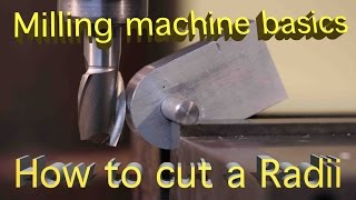
milling radius without rotary table quotation

CAD and a ro"tab are overkill for that port. ( It"s just a lever. No cam or follower surface evident. ) I hate indicating in a ro"tab. Radius gages and freehand grinding to a scribe line are often economical and money making.
For more exact work and for a "machined" look I use the following method. Measure the hole spacings or for a one-off use a transfer punch. Radius gauge the outside curve or insert a wood plug in the hole and pickup the radius using dividers. Rough the blank on the band-saw then drill, bore, and ream the holes. Make a pin for each of the hole diameters. It"s useful if the pins have a tapped hole in the end for a hold-down clamp. Clamp a pin in a V in the soft jaws on the vise. Slip a washer then the part over the pin. Use big vise grips to hold and rotate the part on the pin. Mill radius using reverse spiral end-mill, sneaking up on the radius. ( This takes a touch as the part wants to bounce and grab. ) Don"t go past the tangent to the sides. Leaving the ends of the radius a little short from the tangent help to avoid grabbing and looks fine when you blend. It helps to mill in two sweeps starting from the end of the radius and milling into the center then flip the part and mill the other end. Now, to blend the sides into the radii you just mount the part, side up, in the mill vice and level the part so the radii on each end of the segment are even with each other. This does not have to be exact. Just eyeball it. Slide wedges under the part to take the downward milling force. Cut the side down till it blends with the radius. Repeat for the other sides.

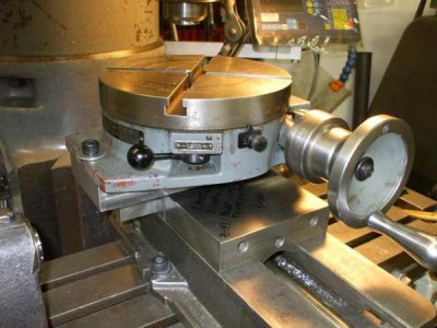
You say you have a rotary table. Use it. Make a setup similar to the photos in RichR"s post. Do conventional milling, which we would find in that last photo where the end mill rotates to the right, and the table would be rotated in a counter clockwise direction, so that the cutter and work are moving in opposite directions. For a plate 3/8 thick I suggest going with a four flute end mill. It will give a fine finish and have less chip load per tooth than a two flute.
What JT showed is something I"ve been doing for years. I have a couple of pivot points I made that anchor into a slot wherever I want it. Positioning the table so the endmill can go into the slot lets you machine the full thickness of the part at one time. Usually that"s a Y axis adjustment, while the X axis sets the radius. The part needs some kind of handle so you can control it as you manually swing the part around. It"s most helpful and much safer if you also set a limit for the rotation of the part. For hogging off material, you probably don"t want to climb mill- think about what could most easily happen- a broken end mill, ruined part, and a nasty bruise would be the least of the worries.
What is shown in that vid is a decent method- a variation is to clamp the work piece to the upright of an angle plate bolted to the table. That is one favored method of mine. You still use the pin, but it nests into a hole in the plate, and a clamp holds the work piece. Typically the distance from the hole in the plate to the surface of the mill table is enough to accommodate the part in a full 180 degree rotation. The height of vise jaws would only allow this for a much smaller part. Going off the side of the jaws gets around this, as shown, but you have to be more careful, and your vise may not clamp the part well with just one side being under pressure- you might have to back up the other side of the jaws with a spacer.
Another way to accomplish this kind of operation is to actually mount the part on a stub and rotate it using a spindex or the like. That"s starting to get pretty close to using a rotary table- and is equivalent to using a rotary table set up with a horizontal axis.
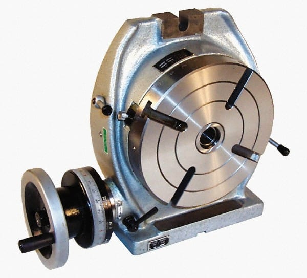
I have a 12" Enco horizontal/vertical rotary table which I keep mounted permanently on my old mill/drill. It has a 1" diameter bore and I made an adapter for my 4" scrolling chuck. A threaded backplate and stud keep it securely fastened. To center the table, I put a scrap piece in the chuck and "turn" a cylinder with an end mill. I then use and edge finder to accurately align the true center of of the rotary table with the spindle axis. A test indicator mounted on the spindle would also work well. The mill has a DRO
I use the table to cut arcs. If the part has a single arc, I position the part so the center of the arc is on the table axis. All the linear features can be made by a combination of x, y and table moves. Just make sure to record the home position before moving and axis! A DRO really shines for this.
Lastly, I had done some very precise pseudo four axis machining by setting the table in a vertical position with the axis parallel with the x axis. The table was centered in the y direction by cutting four square faces, making a cut and rotating 90 degrees and repeating until all four faces were cut. A micrometer was used to measure the resulting square. The end mill position is half the measured thickness. I found the x position by facing the y-z face and locating the edge with a sharp point and a 50x microscope.
A custom tool setter system datum was made from a silver alloy relay contact mounted on the table and wired to an LED indicator. This was because one of the tools used was a .008" micro drill and another was a 0000 center drill. With setup, I could do tool changes very accurately.
Thread milling uses a standard G02 or G03 move to create the circular move in X-Y, then adds a Z move on the same block to create the thread pitch. This generates one turn of the thread;
Outside Diameter (O.D.) Thread MillingO.D. Thread Milling Example, 2.0 diameter post x 16 TPI: [1] Tool Path [2] Rapid Positioning, Turn on and off cutter compensation, [3] Start Position, [4] Arc with Z.
Lagun’s BM RT is a bed type mill with C-Axis rotation and equipped with a rotary table. With a compact and robust design, this milling machine is ideal for machining bulky workpieces on all 5 sides.
Additionally the sturdy, oversized mill bed comes with reinforced ribbing, fortifying its stability during heavy milling. The hardy table, measuring at 63” x 47” (1600mm x 1200mm), column, slide and ram systems have been studied and as a result designed with roller/shoes that exceed the manufacturing requirements. Designed to be as close to the column as possible, the mills ram placement ensures a sturdy column-slide-ram assembly. This results in a rigid and light slide for vertical movement. To correct any ram deflection during cross movement they come equipped with special wedges.
*Note: Interested in more bed type milling machines? Take a look at our BM-C and BM-BL bed mills. Or browse all machining centers offered by Lagun Engineering here.

After the operator enters milling instructions into a computer, the 3-axis CNC machine will automatically complete the task by using a tool to cut along three axes — X, Y, and Z, or left-to-right, front-to-back, and up-and-down. Both CNC milling and CNC turning fall under the umbrella of 3-axis machining. However, they function slightly differently.
When using a 3-axis CNC milling machine, the material block remains fixed in a vice or on a machine bed. Rotating drills or cutting tools are connected to a spindle and move along the X, Y, and Z axes, removing shavings to accurately form the final component. 3-axis CNC milling machines are excellent for producing most geometries and simple parts.
By contrast, in the CNC turning process, the workpiece is attached to a rotating spindle, and a lathe shapes the component. As the spindle holding the workpiece rotates, a center drill or cutting tool traces the component’s outer and inner perimeters or creates holes along the center axis. Compared to CNC milling machines, CNC lathe turning machines produce parts faster and offer cheaper per-unit costs, which is advantageous for high-volume production runs.
Like 3-axis CNC milling, the cutting tool only moves along three axes and doesn’t maintain continuous contact with the workpiece in indexed 5-axis CNC machining. However, the machining table and tool head can automatically swivel in two directions between operations. Indexed 5-axis machining is great for manufacturing housings, jigs, and fixtures. It falls somewhere between 3-axis CNC milling and continuous 5-axis CNC machining in terms of speed, precision, and the ability to handle complex geometries.
Turning mill CNC centers are practically identical to CNC turning machines, with one exception — they’re equipped with CNC milling equipment. The workpiece is attached to a spindle that can either rotate or remain stationary while cutting tools remove material from it. By combining the elements of CNC lathe machines with milling tools, mill-turning CNC centers offer high levels of accuracy and geometric versatility, making them great for creating parts with loose rotational symmetries, such as camshafts or centrifugal compressors.
Not only do these types of 5-axis CNC milling machines offer greater accuracy when machining deeper parts and hardened materials, but they also offer higher yields and faster machining speeds. However, 5-axis machining is more expensive due to the specialized equipment necessary and the need for expert workers.
The main difference between 3-axis and 5-axis milling machines is that the workpiece can be worked on from three axes with the former and five axes with the latter. Both are highly versatile, automated, and replicable production processes that will enable you to quickly and cost-effectively create accurate components. However, you may opt to use one over the other for a variety of reasons.
Still on the fence about using a 5-axis CNC machine vs. a 3-axis machine? Fast Radius can help. Our team of experts can talk you through your CNC machining options and help you choose the process that’s best for your project. As a trustedCNC machining partner, Fast Radius also offers high-quality CNC machining capabilities with router-, lathe-, drill-, and mill-based CNC machining equipment. Contact us today to get started.

I have a rotary table but its the positioning and alignment that"s tricky. My mill has DRO"s so I"m thinking maybe work out the XY coords. for the curve and advance the table accordingly. Need to do this in the next few days so I have a little thinking time (I need it all .. .).
With the rotary table I can get smooth curves easily, but getting them in the correct place is not so easy. Assuming I cut my 4 curved corners, I can then try to align the work on the table so that the horizontal and vertical cuts seamlessly intersect the quadrants. Aligning the endmill to the centre of the end of the quadrant is likely to be tricky.
Using calculated tables will give a more stepped approach, even with a large number of iterations. The potential for errors whilst doing this manually is very high, and I"m not that confident that I can do it 4 times without significant errors. I suspect that it will need at least 100 coords to get the curve to a reasonably smooth profile.
Can"t think of any other ways at the moment. Jigging the rotary table will get the corners more or less correct, but I need a technique to align the endmill to join up the quadrants.

One of these automated fabrication methods is CNC milling. It is a process where rotary cutters remove material, which makes it the opposite of CNC turning.
The milling centres do not just perform the cutting automatically, but also the changing of tools. During the average process of creating a finished product from a block of metal, for example, various tools are used.
These are two of the most prevalent milling operations, each using different types of cutters – the and mill and the face mill. The difference between end milling and face milling is that an end mill uses both the end and the sides of the cutter, whereas face milling is used for horizontal cutting.
These tools usually have a flat bottom but not always. Round and radiused cutters are also available. End mills are similar to drills in the sense that they can cut axially. But the advantage for milling lies with the possibility of lateral cutting.
Slab mills are not that common with modern CNC machining centres. Rather, they are still used with manual milling machines to quickly machine large surfaces. That is also why slab milling is often called surface milling.
Woodruff, or keyseat/keyway cutters are used to cut keyslots into parts, for example shafts. The cutting tools have teeth perpendicular to the outside diameter to produce suitable slots for woodruff keys.
Threading operations are usually carried out on drilling equipment. Using a thread mill, though, is more stable and has fewer limitations regarding the environment.
The cheapest of the bunch. And this is exactly why it still finds use. As carbon steel is not very durable, it is only suitable for low-speed operations.
Cutting ceramic tools are prone to cracking when used on hard materials and with high temperatures. Therefore, they are not really suitable for machining steels, for example. Otherwise, a short tool life is to be expected.
Cemented carbide is another step towards high performance milling because of the aforementioned properties of such milling machine tools. In the long run, they are a more cost-efficient choice while the up-front costs are higher.
For example, if certain inside radii are necessary, the tool cannot deviate from them. At the same time, you can use a large tool for milling away the bulk of it and apply a smaller one to finish the inside corners.
The helix angle, along with the rotation speed of the spindle, determines the cutting speed or feed rate. A steeper angle is suitable for softer materials and metals.
Choosing the right milling cutters for your job needs an understanding of the materials, parameters and definitely some experience. The final outcome depends on these choices and a machinist must understand what material cutters are suitable for cutting different mediums.

CNC machining, or computerized numerical control machining, defines a broad range of material removal processes. Starting with the CAD (computer-aided design) data of a component, we will decide which CNC processes are best suited for the job. Using CAM (computer-aided machining) software, a machine operator/programmer pre-programs the various machines to produce the desired component. Common CNC processes include milling, turning, grinding, EDM, and deep hole drilling.
CNC milling is a process of removing material by using spindle (rotating) mounted tooling. Think of CNC milling as an advanced version of a conventional drill press, where an operator moves the rotating drill bit up and down manually and the part is stationary. A CNC mill will move both the rotating drill (tooling) and the component around to access different areas of the component. The different types of CNC milling processes are commonly defined by the tooling orientation (horizontal and vertical) and the number of axes
Like the drill press mentioned earlier, vertical milling operations have the tooling rotation running vertically (in the direction of gravity). A simple vertical CNC machine as seen in Figure 1 will have three axes where the tooling moves vertically; the table moves from the front to the back of the machine, as well as from side to side. These machines are common in many machine shops because they are cost-effective, simple to program, but still offer diverse capabilities.
Horizontal milling machines have the same primary function as vertical machines— removing material from a component; however, in a horizontal milling machine the tooling spins horizontally. The two different machines can use the same type of tooling as well. Horizontal milling machines are often more expensive but are better suited for production machining. Horizontal milling machines will often have a fourth axis for part rotation and may also have a pallet changer (discussed later).
The machines previously discussed are considered three-axis milling machines. Each additional axis represents an additional type of movement. Going beyond three and four-axis machines greatly expands the capability of a CNC machine. For example, a vertical milling machine may have an added axis which allows the component to rotate. This fixture is called a rotary table and is a common addition to three-axis machines. It is used to gain greater access to different areas of a component.
Turning is a generic term used in the CNC industry to represent the use of a lathe. A lathe’s main function is to create round parts; however, as you will see, a lathe can have much more functionality. The lathe has a chuck that holds and spins the workpiece. The tooling is then moved around the workpiece to remove material. A simple lathe will have tooling that can move in two axes. In more advanced CNC turning equipment, more axes (directions of movement) are utilized to expand the functionality of the lathe. The added axes could be multiple chucks for different stages or the addition of milling type components to create more advanced features.
Like CNC milling, CNC lathes can use various types of tooling to create different features in round parts. These could be features like o-ring grooves, internal and external threads, face grooves, and so on. Lathes will also have a tailstock located opposite and in line with the chuck. The tailstock is used for holding a long workpiece or for completing various drilling functions. Figure 2 is a sectioned (cut in half) part that would be produced using a CNC lathe. Features include internal threads, external threads, outer diameter groove, inner diameter groove, and a face groove.
One major aspect of any drilling operation is how deep a hole can be accurately drilled. The depth limit is typically measured relative to the diameter of the drill. This ratio is called the length to depth ratio. For example, a standard spiral drill is accurate to a length-to-diameter ratio of 5:1. If you were using that drill to produce a .500 diameter hole, a clean and accurate hole should be possible up to 2.5 inches deep. Going deeper is possible, but sticking to the 5:1 ratio is generally best in order to be safe, precise, and repeatable.
Contours are easy to create in CNC operations, but they require longer cycle times to produce. Unless a contour is needed for the part to function correctly, it is best to simplify the surfaces to save on machine time (part cost). Figure 6shows the before and after of a part with and without a contour. Eliminating this contour could drastically reduce the cost of the component. You see the pocket on the underside of the part is simplified as well.
Fillets and radii are good design features for increasing strength and resisting cracking. They also make parts easier to handle and more aesthetically pleasing. Depending on the CNC process, fillets and radii may be inevitable; but in other cases, they may cause unnecessary complications. As an example, since milling operations use a rotating bit, inside corner radii are inevitable. The image below shows an example part with an inside corner radius.
Figure 8 shows a common tooling insert for a lathe (gold color). Nearly all of these types of inserts have a rounded (radiused) end. The radius helps to cut away material more efficiently but will also generate a fillet on inside corners during CNC operations.
If an inside corner for a turned component needs to be sharp, special “zero radius” tooling inserts will need to be used, which results in an added operation and tool setup.
The length to diameter ratio (L:D ratio) discussed earlier also applies to CNC milling. Designing small features that are hard to reach is likely to increase the cost of a component. An example is a thin and deep pocket. For CNC milling, deep and narrow areas require specialized tooling and are time-consuming to produce. They may even require the use of EDM equipment, requiring more setup time and an additional process.
As we mentioned earlier, the CNC milling operation automatically creates a radius on vertical inside corners. If your assembly requires a sharp corner, there are a few options available. The lower two corners in Figure 10 show the corners drilled out. The diameter of the hole is large enough that the vertical and horizontal walls are completely straight. The top two corners use a design feature that accomplishes a sharp corner with a slightly different design.
These features are designed around allowing a mating component to have a sharp corner. That is, something with sharp corners needs to fit into the pocket in Figure 10 above. If the mating component cannot be modified and the above design features are not possible, the corners can be EDM’d to a much smaller radius. As mentioned previously, this is an additional cost and set up that should be avoided
Most lathe tooling has a radius for performance and chip removal, as discussed earlier. However, the radius may work against you if you need a sharp corner. You can design in a small undercut to make sure a mating component with a sharp corner can fully engage into the CNC turned part. Below is a common example of a pin (outlined in red) and a bushing (outlined in blue). The undercut on the pin allows the bushing to fully engage into the face of the pin without interference.
When designing radii on a part, it is best practice to make the radius a non-standard value. That is, instead of having a .250 corner radius, make it slightly over (.260). Doing this ensures that CAM software generates the radius with cutting equipment, rather than allowing a tool to engage fully in a corner. In Figure 13-A, a half inch cutter is fully engaged into a corner with a ¼ inch fillet. The excess contact area causes chattering, which produces a rough finish and may cut the part slightly undersize.Figure 13-B is zoomed in more and shows the difference in contact area when a corner radius .260. The difference in design is small but makes the CNC process more robust. If a fillet is specified to be ¼ inch, an operator may program it to use a smaller tool to avoid full engagement. Doing so adds another setup and another operation (increasing cost slightly).
In general, smaller features take more time to make. For example, since a CNC milled pocket will generate an inside radius, it is better to have a radius at .260 than .100. In the example part shown below, the corner radii are highlighted in blue. The corner radius is .260 and therefore, can be produced by a half inch mill. That same tooling bit would likely be able to cut this entire part as well. If these radii were reduced to.135 , a 3/16 mill would be largest diameter tool able to produce the radius.
The smaller tooling may not serve much of a purpose beyond cutting the smaller radius. Therefore, the smaller radius would require the setup of another tool, a tool change, and additional programming. Keep in mind that design features like these are relative to the part design as a whole. If the part is small, then small features are unavoidable. The basic premise is that having lots of different design features that require several different types of tooling should be avoided when possible. It is also advantageous to keep sizes consistent throughout the part design.
Different CNC processes will leave different surfaces finishes. Leaving those surface finishes as they are is the most cost-effective and straightforward finish. The chart below shows some CNC operations and what range of surface finishes can be expected. Note that smoother surface finishes are possible without changing the operation but may require different tooling and extended machine time (higher cost).

The TR160 5 Axis Rotary Tables, manufactured by Haas, consist of dual axis Trunnion rotary table that is capable of tilting up to 160 mm. It also has a scale assessment ...
The TR210 is HAAS"S rotary table developed and configured to be integrated with HAAS"S mills 4th and 5th axis drivers to provide complete and optimum operation. It has a diameter of 210 mm made from trunnion ...
... space with high load capacity. The individual rotary tables are equipped with Harmonic Drive units, which ensure high moment load capacities and high concentricity and axial runout accuracies.
The work table is graduated 360 degrees around its circumference and is driven by a precision Worm and Gear providing a 90:1 reduction ratio. One turn of the Handle moves the Table through 4 degrees. ...
... Tilt-Yaw (A/B) two-axis rotary assembly provides high-speed machining capabilities for complex 3D part geometries. The precision-aligned system allows accurate positioning on a hemispherical surface. ...
... ) MDR two-axis rotary assembly provides high-speed machining capabilities for complex 3D part geometries. The precision-aligned system allows accurate positioning on a hemispherical surface. Uses cost-effective ...
... ) MDR two-axis rotary assembly provides high-speed machining capabilities for complex 3D part geometries. The precision-aligned system allows accurate positioning on a hemispherical surface. Uses cost-effective ...
Our FÖRSTER swivel welding tables offer maximum working comfort for all-round welding of complex assemblies. Ideal for all tasks due to a variable arrangement of our patented T-slot system.
The hydrostatic rotary tables from ZOLLERN impress with their durability and a high concentricity and axial runout accuracy. Thanks to the ZOLLERN bearing clearance compensator, the optimal pocket pressure ...
... the table is the rotation, the user may require the rotary table for drilling operations and milling. Using the servo drives in conjunction with the machine CNC control ...


 8613371530291