
torque motor rotary table free sample
HIWIN Corporation Torque Motor Rotary Tables (TMRT) use a direct-drive torque motor, built-in high-rigidity and high-precision bearings, absolute encoders and powerful brake system to ensure excellent acceleration capabilities and high precision uniform movements. HIWIN TMRTs are backlash-free, optimized for high torques, have robust dynamics and are highly adaptive to the most demanding of automation processes. Compared with the mechanical indexing table, TMRT has high speed and high torque characteristics, suitable for the needs of various machining equipment.
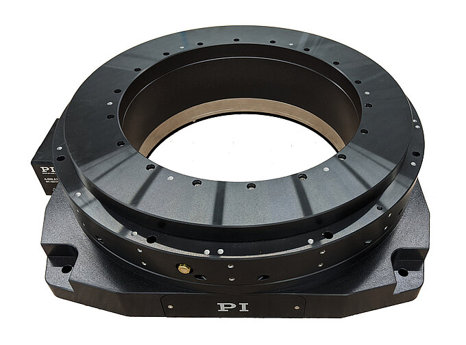
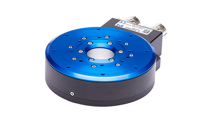
PI’s direct-drive rotary tables with frictionless, brushless, closed-loop torque motors provide the best combination of high accuracy, high velocity, and maximum service life. PI provides closed-loop direct drive rotary tables with both mechanical bearings and air bearings. Stage models with large apertures and low profile are available. The stage design is optimized for high speed, stiffness, and high load capacity. If completely friction-free and maintenance free motion with virtually unlimited lifetime is required, air bearing rotation tables are recommended. These ultra-precision, high-speed rotary tables provide vibration-free motion with extremely high accuracy and negligible runout, wobble and eccentricity errors. The lack of lubricants makes these also clean room compatible and ideal for any high-performance metrology application in optics, photonics, and semiconductor manufacturing, test and metrology related projects.
In contrast to worm gear driven rotary stages or belt-drive rotation stages, torque-motor direct drive stages eliminate play in gears, couplings or flex in drive belts, providing motion with zero backlash and excellent constancy of velocity, while achieving higher speed than worm-gear drives.
PI’s precision direct-drive, positioning tables can be used in high performance factory automation, research, semiconductor, and laser processing applications. Due to the use of brushless high-torque, motors with direct metrology position feedback, backlash is completely eliminated, and reliability is greatly improved.
With modern direct-metrology rotary encoders, sensor resolution down to 1/100th of a microrad is available on select models with large rotary table platforms, using the high interpolation factors
Based on the high encoder resolution and powerful servo controllers, the direct-drive rotary tables also provide excellent velocity control, which is required in automation applications including high-speed laser processing, indexing, and semiconductor wafer inspection.
Most Direct Drive Rotation stages can be mounted horizontally and vertically, and with combinations all 3 rotary degrees of freedom (3DOF, pitch, yaw, and roll) can be addressed.
Our direct drive rotary tables provide high torque and are easy to integrate. They contain high-energy magnets in a simplified mechanical design and drive loads directly without the need for a transmission mechanism or gearbox. It allows customers to build them right into a drive system for flexible placement and integration with cooling pipes and cables, for example.
We supply a wide range of frameless motors, and our adjustable motors include an optical encoder, scale, bearing and housing. Given our selection, it can be challenging to choose the best direct drive motor for your project. Our engineers prefer to help you find the right rotary table for your requirements.
Our most popular rotary motor, the AXD series is characterized by a slim, compact "pancake" design with high peak and continuous torque despite the motor"s quite small form factor.Direct drive and brushless motor
The ACD series is a set of ironless rotary tables. This motor is cogging-free and features high-resolution optical encoder feedback and low speed variability. This permanent magnet motor is equally suited for either low or high speed applications.Zero cogging coreless motor
The ACW series features a cogless construction and lean design, with high-precision coding and ultra-precision bearings. Together, this results in our highest performing motor in terms of repeatability and smooth motion.Direct drive brushless motor
The ADR-A series is available with both low and high speed windings and is fully equipped with an encoder and bearing. This series has a high slot fill factor and generates very high torque.Direct drive brushless permanent magnet motor
The ADR-B range performs at a similar slot fill factor and torque density to the ADR-A range, but has a larger center hole compared to its equivalent.Direct drive brushless permanent magnet motor
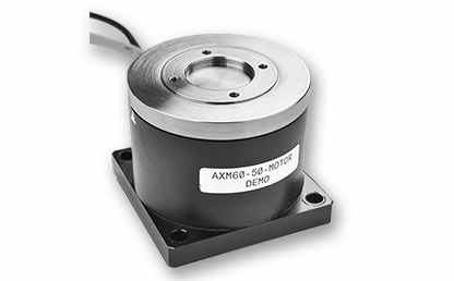
Similar to the ACD series, the AXM series also features an ironless design and zero noise characteristics. This motor has a compact design, making it ideal for applications with specialized size requirements.Direct drive brushless permanent magnet motor
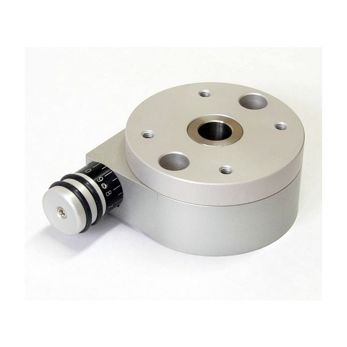
The TauDisc ND-s series of direct drive rotary tables from Nikki Denso are compact, have a short axial length and a wide torque range. The rated torques cover 5 to 500Nm. Peak torque up to 1,000Nm. Hollow-shaft (throughbore) up to 68mm. The integrated angle encoder is a high-precision type for 25 or 26 bits of resolution, which enable a high positioning accuracy. The following options for radial and axial runout are available:

A popular question that we hear is, “How do I size a motor for my application?” This post looks at an example Rotary Index Table application and provides the equations and considerations needed to make the appropriate motor selection.
First, consider your machine’s movement. In our sample case of a Rotary Index Table, an engineer will need to first define all relevant information that will be used later in the Torque calculation. Typical information we will need includes:
The move profile can indicate a linear or rotational movement. The total area under the velocity curve defines the total move distance. Utilizing the data from the move profile will allow us to define the required maximum output speed of the motor.
Since we want to define the required motor torque, we want to be sure that we are using values that pertain directly to the motor itself. If there is a gearbox in the system, we need to be sure to reflect the required values back to the motor. We will need to determine the acceleration torque, deceleration torque, constant torque, and any torque due to gravity on the system. For this exercise, we will assume the index table is in a horizontal position, so the torque due to gravity will be zero.
Using the maximum angular velocity and deceleration times, we can calculate the angular acceleration, αaccel_motorand angular deceleration, αdecel_motor.
Once we know the angular acceleration of the motor, we need to calculate the inertia of the load connected to the motor. In this case, we can approximate the index table inertia using the formula for a solid cylinder.
The load on the index table must also be taken into account. If the load is distributed evenly over the indexed surface, we can add this load into table weight to calculate the inertia of the complete system. If the load is not distributed evenly, then a separate load inertia will need to be determined, Jload.
Now that we know our inertia and our acceleration and deceleration rate, we can determine the required torque. If known, we can add in the inertia of the motor, Jmotor, the gearbox, Jgearbox and a brake on the motor, Jbrake,if the system has a brake.
Depending on the design of the system, there may be a constant friction torque, Mfriction, which must also be accounted for in the motor sizing. The amount of this constant torque will be dependent on the friction coefficient of the system and the weight of the table and load. Again, if there is a speed reduction in the system we can reflect this back to the motor shaft.
We can calculate the required torque for each of the operating sections of the move profile. The acceleration (Figure 2), constant run (Figure 3), and deceleration (Figure 4).
Note that the friction torque helps to slow the system. This can be used to allow the time to decelerate the system to be reduced and the time to accelerate the system increased. This has the advantage of decreasing the peak torque requirement of the motor. If the application allows a faster deceleration time, this may allow the motor size to be reduced.
In addition to determining if the motor has sufficient torque to make the move as defined by the move profile, we must also verify the rms motor torque over the complete cycle is less than or equal to the rated torque of the motor. If the rms torque is higher than the rated torque of the motor, the motor may overheat.
To calculate the rms torque over the cycle, we need to know the dwell time between cycles, tdwell, and the constant run time of the move profile if it is a trapezoidal move.
Optimizing the motor sizing for an indexing application can be an iterative process. By calculating the peak requirements and rms torque of the application, the selection of the motor can be done with confidence to provide a reliable solution for the application (see Figure 7).
In our example, we would want to make a motor selection that offers rated torque above the calculated rms torque value across the needed speed range. Additionally, we would want to make sure the peak torque (red line) is more than the calculated maximum torque value.
Do you have questions about choosing the correct motor size and technology for your application? Contact a KEB Engineer today to discuss your machine design.
Ensure that your servo drive can handle the Nominal- and Peakcurrent of the Motor. An adjustment of the Speed and DC Bus Voltage can be done after consultation. The nominal data in this datasheet are based on an ambient/coolant temperature of 20°C.
Because the exact duty type depends also on the thermal connection of the motor, the embedded thermal monitoring system has to be analysed and attented. However, attention has to be payed that the temperature sensors do not show the exact temperature of the winding and this could be up to 20 K higher due to thermal capacities. Despite an electrical insulation towards the winding, you are only allowed to connect the sensors to your controller by using a galvanic separation in between.
There is no theoretical limit to the speed of a linear engine because there is no contact. However, speed is typically limited by the mechanical bearings. For example, the maximum speed for linear control systems with rails and guide cars is usually limited to 5m/s. Therefore, the speed for linear motors in most applications is limited to 5m/s. The use of ceramic ball bearings allows speeds of up to 10m/s. By using air bearings, higher speeds can also be possible.
There is no length limit for linear motors. This is because the engine tracks can be connected to each other in sections. The linear rails can also be connected to each other. The linear scale for donor repatriation can be delivered in large lengths as well. Therefore, linear engine applications can be built up to 20m or even longer.
If the current is suddenly interrupted, a linear motor can move on under its own inertia, until it encounters the final attack or comes to a halt due to friction force. This is not usually a problem, but it can be a problem for some applications. It is possible to install a brake with the linear motor, which will be activated, when power interrupts. In this way, the engine can stop immediately. Such a brake is typically installed on the rails of the linear guidance.
Linear Motors can be used in cleanroom environments. In fact, many front-end semiconductor applications have linear motors in use. In wafer manufacturing plants, high-precision lithography machines, for example, use linear motors in XY positioning tables with very high accuracy (nanometer resolution) and submicron accuracy in cleanroom classes according to ISO 2.
After about 100mm, the magnetic field is weaker than the geomagnetic field. If the magnetic trajectories are still shielded by iron, for example at the torque engines, virtually no magnetic field can be measured outside the housing.
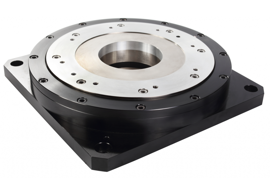
A turbo among rotary tables – the new FIBRODYN DA direct driven rotary tables with torque motor are optimally suited for all handling and assembly applications that require the shortest indexing times and flexible positioning. Thanks to its measuring system directly in the rotary table axis, any position can be moved to with the highest precision. The slim design with its very space-saving, compact construction and its fitted boreholes makes it very easy to integrate the rotary tale into your system. FIBRODYN DA is also available as decentralized stand-alone solution with integrated control. In this version, it offers the ideal opportunity to save a separate external NC control to minimize the implementation and start-up costs and to realize small machines without complex peripherals. The rotary tables are lifetime lubricated and maintenance free.


 8613371530291