
asme safety valve testing requirements factory
The Pressure Safety Valve Inspection article provides you information about inspection of pressure safety valve and pressure safety valve test in manufacturing shop as well as in operational plants.
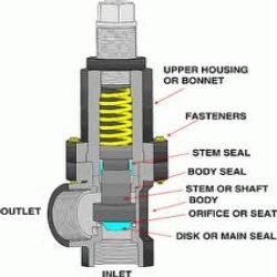
Your pressure safety valve is a direct spring-loaded pressure-relief valve that is opened by the static pressure upstream of the valve and characterized by rapid opening or pop action.
Your construction code for pressure safety valve is API Standard 526 and covers the minimum requirements for design, materials, fabrication, inspection, testing, and commissioning.
These are:API Recommended Practice 520 for Sizing and SelectionAPI Recommended practice 521 Guideline for Pressure Relieving and Depressing SystemsAPI Recommended Practice 527 Seat Tightness of Pressure Relief Valves
For example in the state of Minnesota the ASME Code application and stamping for pressure vessel and boiler is mandatory which “U” and “S” symbols are designated for stamping on the nameplate.
For example if there is pressure vessel need to be installed in the state of Minnesota then the pressure vessel nameplate shall be U stamped and pressure vessel safety valve shall be UV stamped.
National Board Inspection Code (NBIC) have own certification scheme for pressure safety valves and using NB symbol. The NBIC code book for this certification is NB 18.
National Board Inspection Code is assisting ASME organization for ASME UV symbol certification by providing ASME designee in manufactures auditing program.
There are some other standards and codes which are used in pressure safety valve such as:ASME PTC 25 for pressure relief devices which majorly is used for assessment of testing facility and apparatus for safety valvesBS EN ISO 4126-1, 4126-2 and 4126-3 which is construction standard similar to API STD 526.
This API RP 527 might be used in conjunction of API RP 576 as testing procedure for seat tightness testing of pressure safety valve for periodical servicing and inspection.
These are only important points or summery of points for pressure safety valve in-service inspection and should not be assumed as pressure safety valve inspection procedure.
Pressure safety valve inspection procedure is comprehensive document which need to cover inspection methods to be employed, equipment and material to be used, qualification of inspection personnel involved and the sequence of the inspection activities as minimum.
You may use following content as summery of points for Pressure Safety Valve Inspection in operational plantDetermination pressure safety valve inspection interval based API STD 510 and API RP 576 requirementsInspection of inlet and outlet piping after pressure safety valve removal for any foulingInspection of pressure safety valve charge and discharge nozzles for possible deposit and corrosion productsTaking care for proper handling of pressure safety valves from unit to the valve shop. The detail of handling and transportation instruction is provided in API RP 576.Controlling of seals for being intact when the valves arrived to the valve shop.Making as received POP test and recording the relieving pressure.
If the POP pressure is higher than the set pressure the test need to be repeated and if in the second effort it was near to the set pressure it is because of deposit.If in the second effort it was not opened near to the set pressure either it was set wrongly or it was changed during the operationIf the pressure safety valve was not opened in 150% of set pressure it should be considered as stuck shut.If the pressure safety valve was opened below the set pressure the spring is weakenedMaking external visual inspection on pressure safety valve after POP test. The test need contain following item as minimum;the flanges for pitting and roughness
Making body wall thickness measurementDismantling of pressure safety valve if the result of as received POP test was not satisfactoryMaking detail and comprehensive visual and dimensional inspection on the dismantled valve parts (after cleaning)Making special attention to the dismantled valves seating surfaces inspection e.g. disk and seat for roughness, wear and damage which might cause valve leakage in serviceReplacing the damaged parts in dismantled valves based manufacture recommendation and API RP 576 requirementsMaking precise setting of the pressure safety valve after reassembly based manufacture recommendation or NB-18 requirements
Making at least two POP test after setting and making sure the deviation from set pressure is not more than 2 psi for valves with set pressure equal or less than 70 psi or 3% for valves with set pressure higher than 70 psiMaking valve tightness test for leakage purpose after approval of the setting pressure and POP tests. The test method and acceptance criteria must be according to the API RP 576.The API RP 527 also can be used for pressure safety valve tightness test.Recording and maintaining the inspection and testing results.

When it comes to understanding pressure relief valve testing requirements, there’s a lot of information out there, but not all of it seems conclusive. If you’re new to pressure relief valves or are getting started in a new industry, it can be tough to decipher what testing requirements your facility needs to meet.
While we can’t provide the specific testing requirements for every industry, we can offer a few general testing requirements, and point you in the right direction to find the information you need for your facility’s unique testing requirements:
It’s good to keep in mind that every industry and region has unique pressure relief valve testing requirements. Your facility may be required to just bench test pressure relief valves every five years, or you may have to test valves every year, but bench test and repair valves every three to five years. There is a large variance in the testing requirements for pressure relief and safety valves depending on your industry and your region. That said, there are a few general testing requirements we can look at to start with.
The National Board Inspection Code, created by the National Board of Boiler and Pressure Valve Inspectors, makes the following recommendations on the frequency of testing for safety and pressure relief valves, depending on the temperature, psi, and function of your boiler:
High-pressure steam boilers greater than 400 psi should be pressure tested to verify nameplate set pressure every three years, or as determined by operating experience as verified by testing history.
It’s important to remember that these are general pressure valve testing recommendations. For specific requirements, you’ll have to verify your unique jurisdictional and industry code requirements. See the resources below for more information.
The National Board Inspection Code is an industry-recognized name offering quality information on pressure relief valve testing requirements. Here, you’ll find a wealth of information and testing best practices.
The ASME is another organization setting pressure relief valve testing requirements, and offering the necessary training engineers need to test and understand the testing procedures for pressure relief valves. In addition to testing requirements and standards, the ASME offers a variety of online courses on pressure relief valves, from fabrication and proper installation to inspection and repair.
For specific testing standards, it’s best to check with your industry and your regional jurisdiction. Pressure relief valve testing requirements can vary by state or region and are most often industry-specific. Check your industry’s standards, and check local code requirements to ensure your facility is adhering to the most relevant pressure relief valve testing requirements.
When you’re looking for the pressure relief valve testing requirements relevant to your facility, it’s important to understand the different testing methods that are available to you. It’s likely that regardless of your industry if you have safety and pressure relief valves in use at your facility, you’ll have to bench test those valves at least every five years.
In addition to those bench tests, though, you’ll also have to perform manual or on-site pressure relief valve testing. Here’s a quick look at the three most common pressure relief valve testing methods you’ll see when researching pressure relief valve testing requirements:
The most commonly mandated form of pressure relief valve testing, bench testing is unique in that it requires you completely shut down your facility’s system and remove all pressure relief valves. The valves are then transported to a lab where they are tested and repaired as necessary. Tested valves are then re-installed in your system.
Bench testing is the most involved method of pressure relief valve testing, but as this is how valves are tested when they’re manufactured, the industry considers this to be the most thorough testing method.
Inline testing is another accurate pressure relief valve testing method that doesn’t require the removal of valves or facility downtime. With inline safety relief valve testing equipment, a trained technician can test valves in the system to calculate the real setpoint of a valve in the system.
While inline testing cannot take the place of mandated bench testing, it is a more efficient form of testing for other regular testing requirements. Inline pressure relief valve testing is the ideal choice for any required testing that does not have to be bench testing, as it eliminates the need for downtime while still providing exceptionally accurate results.
Some pressure relief valve testing requirements will call for regular manual testing for freedom of operation. This is a basic test that can be done on-site. To complete an operated-in-place test, the test lever on the valve is manually activated. This test functions to ensure that the valve can open and shut tightly, but it does not verify at what pressure the valve opens and shuts. This is a test that may be required quarterly or bi-annually, to ensure the most basic functionality of safety relief valves.
Pressure relief valve testing is necessary for any facility with safety relief and pressure relief valves. For more information about the equipment you need for pressure relief valve testing, the profitability of certain testing methods, and more, head to the AccuTEST blog. There, you’ll find a variety of resources on everything from implementing inline safety relief valve testing to minimizing plant downtime.
If your company requires regular pressure relief valve testing, you might be interested in AccuTEST’s high-tech equipment. Offering inline testing with accurate, repeatable results, our system is the best on the market. See how our equipment works in real-time — schedule a live webinar demo today.
The primary role of a safety relief valve is to prevent over-pressure situations in pressurized vessels or systems. If the tank’s relief valve fails, it can lead to an accident that destroys property, life, or landscape.
The National Board of Boiler and Pressure Vessel Inspectors is one of the governing bodies for the testing and/or repair of ASME Safety Relief Valves.
You, as the owner of the valve, can test it, but it must be done in accordance with the National Board Inspection Code and your state’s and/or local regulations.
Based on the National Board Code, which bases their inspection intervals on what type of service the valve is used for, the following intervals are suggested:
Also, keep in mind that this piping should be oriented so that no liquid relieved through this piping can flow back and rest on the ASME safety relief valve’s outlet port.
The ASME relief valves are set to fully open at its “set” pressure but will begin to partially open before then – normally at 10% below its set pressure.
If your valve is allowed to do this, trash and/or corrosion can set in over time which could prevent the valve from either closing completely or from fully opening, either of which is not a favorable solution.

The ASME Pressure Relief Device (PRD) Testing Laboratory Accreditation Program accredits manufacturers of pressure relief devices and assemblers of pressure relief valves. It is a hybrid program in that it accredits both the manufacturer and specific personnel within the manufacturing organization (the authorized observer). It is operated in conjunction with The National Board of Boiler and Pressure Vessel Inspectors. Therefore, a manufacturer seeking this accreditation submits an application directly to ASME, but details about the program and review process can be found on The National Board of Boiler and Pressure Vessel Inspector"s website.
Companies that have been accredited through the PRD Accreditation Program are operating in accordance with the applicable rules of the associated ASME BPVC, the ASME PTC-25 standard, "Pressure Relief Devices," as well as one of the standards of construction accepted by The National Board of Boiler and Pressure Vessel Inspectors.
Your pressure relief valves (PRVs) are some of the most important pieces of equipment in your plant. They are what protects your systems from overpressure events that can damage your systems and, in some cases, have catastrophic consequences.
One of the most common questions we get is about relief valve testing frequency. There is no single answer that’s right for every valve or application. It depends on the service conditions, valve condition, and level of performance desired.
Effort should be made to conduct inspections and testing of pressure relieving devices at the time they become due in accordance with the schedule previously established, assuming that the equipment has been in continuous operation, interrupted only by the normal shutdown.
The required testing frequency depends on the service. For example, a valve used in a corrosive or fouling service needs to be tested more often than the same valve used in a noncorrosive, nonfouling service. Other conditions that call for shorter testing intervals include:
It’s also important to look at the valve testing history over time. If the valve consistently passes the test, then it can be tested less often. If the results are inconsistent, then the valve should be tested more often. For new processes, especially those where the service conditions (corrosion, fouling, etc.) can’t be accurately predicted, the initial inspection should be performed “as soon as practical after operations begin to establish a safe and suitable testing interval.”
Our valve technicians are factory-trained and ASME and National Board certified to test PRVs from all valve manufacturers.Contact us to learn how we can help you keep your plant up and running.
Safety is of the utmost importance when dealing with pressure relief valves. The valve is designed to limit system pressure, and it is critical that they remain in working order to prevent an explosion. Explosions have caused far too much damage in companies over the years, and though pressurized tanks and vessels are equipped with pressure relief vales to enhance safety, they can fail and result in disaster.
That’s also why knowing the correct way to test the valves is important. Ongoing maintenance and periodic testing of pressurized tanks and vessels and their pressure relief valves keeps them in working order and keep employees and their work environments safe. Pressure relief valves must be in good condition in order to automatically lower tank and vessel pressure; working valves open slowly when the pressure gets high enough to exceed the pressure threshold and then closes slowly until the unit reaches the low, safe threshold. To ensure the pressure relief valve is in good working condition, employees must follow best practices for testing them including:
If you consider testing pressure relief valves a maintenance task, you’ll be more likely to carry out regular testing and ensure the safety of your organization and the longevity of your
It’s important to note, however, that the American Society of Mechanical Engineers (ASME) and National Board Inspection Code (NBIC), as well as state and local jurisdictions, may set requirements for testing frequency. Companies are responsible for checking with these organizations to become familiar with the testing requirements. Consider the following NBIC recommendations on the frequency for testing relief valves:
High-pressure steam boilers 400 psi and greater – pressure test to verify nameplate set pressure every three years or as determined by operating experience as verified by testing history
High-temperature hot water boilers (greater than 160 psi and/or 250 degrees Fahrenheit) – pressure test annually to verify nameplate set pressure. For safety reasons, removal and testing on a test bench is recommended
When testing the pressure relief valve, raise and lower the test lever several times. The lever will come away from the brass stem and allow hot water to come out of the end of the drainpipe. The water should flow through the pipe, and then you should turn down the pressure to stop the leak, replace the lever, and then increase the pressure.
One of the most common problems you can address with regular testing is the buildup of mineral salt, rust, and corrosion. When buildup occurs, the valve will become non-operational; the result can be an explosion. Regular testing helps you discover these issues sooner so you can combat them and keep your boiler and valve functioning properly. If no water flows through the pipe, or if there is a trickle instead of a rush of water, look for debris that is preventing the valve from seating properly. You may be able to operate the test lever a few times to correct the issue. You will need to replace the valve if this test fails.
When testing relief valves, keep in mind that they have two basic functions. First, they will pop off when the pressure exceeds its safety threshold. The valve will pop off and open to exhaust the excess pressure until the tank’s pressure decreases to reach the set minimum pressure. After this blowdown process occurs, the valve should reset and automatically close. One important testing safety measure is to use a pressure indicator with a full-scale range higher than the pop-off pressure.
Thus, you need to be aware of the pop-off pressure point of whatever tank or vessel you test. You always should remain within the pressure limits of the test stand and ensure the test stand is assembled properly and proof pressure tested. Then, take steps to ensure the escaping pressure from the valve is directed away from the operator and that everyone involved in the test uses safety shields and wears safety eye protection.
After discharge – Because pressure relief valves are designed to open automatically to relieve pressure in your system and then close, they may be able to open and close multiple times during normal operation and testing. However, when a valve opens, debris may get into the valve seat and prevent the valve from closing properly. After discharge, check the valve for leakage. If the leakage exceeds the original settings, you need to repair the valve.
According to local jurisdictional requirements – Regulations are in place for various locations and industries that stipulate how long valves may operate before needing to be repair or replaced. State inspectors may require valves to be disassembled, inspected, repaired, and tested every five years, for instance. If you have smaller valves and applications, you can test the valve by lifting the test lever. However, you should do this approximately once a year. It’s important to note that ASME UG136A Section 3 requires valves to have a minimum of 75% operating pressure versus the set pressure of the valve for hand lifting to be performed for these types of tests.
Depending on their service and application– The service and application of a valve affect its lifespan. Valves used for clean service like steam typically last at least 20 years if they are not operated too close to the set point and are part of a preventive maintenance program. Conversely, valves used for services such as acid service, those that are operated too close to the set point, and those exposed to dirt or debris need to be replaced more often.
Pressure relief valves serve a critical role in protecting organizations and employees from explosions. Knowing how and when to test and repair or replace them is essential.
A: Maintenance should be performed on a regular basis. An initial inspection interval of no longer than 12 months is recommended. The user must establish an appropriate inspection interval depending on the service conditions, the condition of the valve and the level of performance desired.
The ASME Boiler and Pressure Vessel Code does not require nor address testing installed valves. The only thing the code states are design and installation requirements, such as some valves must have a lifting lever. For instance for Section VIII:
“Each pressure relief valve on air, water over 140° F, or steam service shall have a substantial lifting device which when activated will release the seating force on the disk when the pressure relief valve is subjected to a pressure of at least 75% of the set pressure of the valve.”
A: This drain hole is required on some models by the ASME Boiler and Pressure Vessel Code. It is intended to prevent any condensate from accumulating in the body that may freeze or corrode internal valve parts and prevent the valve from opening. The drain hole should be piped away to safely dispose of any discharge or condensate.
A: This is often a confusing topic. The correct installation often looks backwards from what appears to be correct. A paper instruction tag illustrating the proper connection is attached to each valve. Vacuum valves should have the NPT threads that are cast integral to the body attached to the vacuum source. See the assembly drawing for additional clarification.
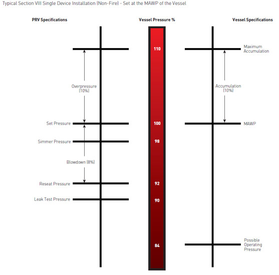
A: Typically, the valve should be nameplate set to open at the MAWP (Maximum Allowable Working Pressure) of the vessel the valve is intended to protect. There is a tolerance to actual set pressure, which means a valve set at 100 psig nameplate may open slightly above or below 100 psig. Consult the current ASME Boiler and Pressure Vessel Code for tolerance classes and special situations when the set pressure may be different than the MAWP.
A: It is normal for spring-operated safety valves to exhibit leakage or simmer/warn, as the system operating pressure approaches the nameplate set pressure, typically in the 80%-90% range of nameplate set pressure. The ASME Boiler and Pressure Vessel Code does not require a specific seat tightness requirement. A certain level of leakage is allowed per manufacturers’ literature and API-527 Seat Tightness Performance Standards, both of which can be found in the Technical Reference Catalog and in the Data Supplement, summarized as follows:
API-527 Standard Seat Tightness Performance: A Functional Test Report (FTR) is automatically provided for valves ordered to API-527. See API 527 for complete details.
A: Maintain a minimum operating gap of 10% between the system operating pressure and the safety valve’s nameplate set pressure. Since direct spring-operated safety valves may “simmer” or “warn” at 90% of the nameplate set pressure, and since the factory standard leak test is performed at 80% of nameplate set pressure, better seat tightness performance can be expected with an operating gap of 20%.
Variance of set pressure is allowed, i.e., a Section VIII air valve with a nameplate of 100 psig set pressure may open from 97 psig to 103 psig, but will be factory set around 102 psig.
Gage issues may lead to incorrect reporting of set pressure. Ensure the gage is within calibration and is accurate for the pressure being measured. Rapid increases in system pressure (more than 2 psig/second, water hammer, reciprocating pumps) can make the valve appear to be opening early because the gage cannot accurately report the pressure to which the valve is exposed.
A: Yes. Section I valves have more stringent setting blowdown requirements and may be used in Section VIII steam applications since they meet all the requirements as specified in Section VIII UG-125(a) “Pressure Relief Devices,” which states pressure relief devices must be “in accordance with the requirements of UG-125 through UG-137.” In addition, UG-125(b) actually specifies that even unfired steam boilers MUST use a Section I pressure relief device.
A: Section VIII UG-136(a)(3) states, “Each pressure relief valve on air, water over 140° F (60° C), or steam service shall have a substantial lifting device which when activated will release the seating force on the disk when the pressure relief valve is subjected to a pressure of at least 75% of the set pressure of the valve.”
The user has a documented procedure and an associated implementation program for the periodic removal of the pressure relief valves for inspection and testing, and repair as necessary.
A: Back pressure reduces set pressure on a one-to-one basis, i.e., a valve set at 100 psig subjected to a backpressure at the outlet of 10 psig will not actuate until system pressure reaches 110 psig. Back pressure drastically reduces capacity; typically backpressure of 10% of set pressure will decrease capacity by 50%. Specific capacity reduction should be determined by the user on a case-by-case basis by flow testing. Back pressure in excess of 10% of set pressure is not recommended.
A: The ASME Boiler and Pressure Vessel Code does not have blowdown requirements for Section VIII (or non-code) valves. Blowdown may vary from less than 2% to more than 50%, depending on many factors including: valve design, dimensional tolerance variation, where the set pressure falls in the set pressure range of a spring, spring rate/force ratio, warn ring/guide settings, etc. Typical blowdown for most valves is 15% to 30%, but cannot be guaranteed. VM
Jim Knox is president, Allied Valve, Inc. (www.alliedvalve.com), a valve repair service company and supplier of Tyco Kunkle and Dresser Consolidated safety valves in the Midwest. Reach him at knoxj@alliedvalveinc.com.
ValvTechnologies and Severn Glocon have reached a partnership agreement that will see collaboration between two of the world’s leading engineering and manufacturing companies specializing in innovative, high-end, severe-service valves.
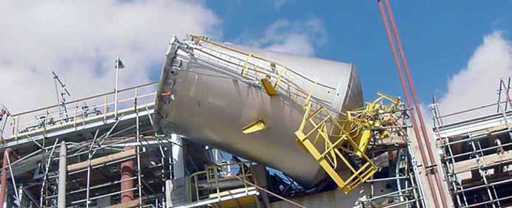
This article outlines the challenges of lifting large valve assemblies weighing several tons and illustrates the industrial rigging equipment and lifting operations typically used for these valves.

Pressure relief devices are used to protect pressure equipment and systems from exceeding the accumulation of over-pressure which may build up as a result of operational upsets, equipment failure or in the event of a fire. These items are safety-critical and in the world of pressurised equipment can be considered the last line of defence.
Failure of these devices to function correctly may lead to a serious accident or explosion; therefore, it is vitally important that these valves are adequately designed, inspected and maintained.
If you are unsure on whether this course meets your requirements and career progression, or if you have any uncertainty on what we have discussed, please contact us for additional advice.

Pressure relief valves (PRVs) are a critical line of defense for pressure vessel protection in the power industry. Generating facilities worldwide depend upon these devices to sense and quickly relieve overpressure conditions to avoid catastrophic damage during process upsets. To ensure these valves will perform as expected, mechanical engineering regulatory bodies mandate the valves be tested on a routine basis.
Some installations make the option of pulling the valve for servicing and testing very difficult. This is particularly true for large size valves, and in the nuclear power industry where valves may be located inside containment areas, making valve access particularly problematic. Fortunately, there is another approved method of testing relief valves for this situation, and this alternative solution is the subject of this article.
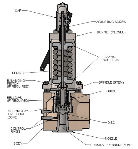
PRVs are relatively, but deceptively, simple devices. They consist of an inlet nozzle attached to the process, which is blocked by a disc held tightly on the nozzle seat (Figure 1). The disc is kept closed by a spring, with adjustments carefully made to dial in the setpoint of the valve.
1. A pressure relief valve (PRV) protects equipment by automatically opening to vent process media when the pressure in the inlet nozzle overcomes the downward force of the spring. Courtesy: Emerson
When the process reaches set pressure, the upward force of the process media offsets the downward force of the spring and the disc lifts off the seat. The process media is relieved through the valve outlet until pressure falls below the setpoint. At this point, the downward force of the spring overcomes the upward force of the process media, and the valve closes.
To ensure the PRV will function when called into action, the American Society of Mechanical Engineers (ASME) mandates relief valves be functionally checked on a routine basis. Typically, a plant will pull smaller valves from their installed position during process outages, and then inspect and test them in a shop environment to confirm they will function as desired and open at the proper pressure setpoint. However, this method of testing is not so easily achieved in certain cases.
Some relief valves are very large and/or located in difficult to reach areas. Others are welded into place and not easily removed from the process. Valves inside nuclear containment areas are particularly troublesome since access to these areas is usually restricted, with strict adherence to extensive protocols required for entry.
To handle these challenging situations, ASME provides alternate means of testing relief valves, as documented in ASME Performance Test Code (PTC) 25 Pressure Relief Devices. These test methods include in-service testing, which allows the plant to functionally test the relief valve without removing it from the process. This in-situ test method can be quite accurate and effective, but only if it is performed correctly with the right equipment.
Service and testing of PRVs is typically performed during regular maintenance outages as defined by ASME guidelines. Operating pressures and temperatures are brought down to levels conducive for servicing, and the PRVs are tested by maintenance technicians. For this type of in-service, or in-situ testing, lift assist devices are used in conjunction with these lower system pressures to verify the PRV will operate at the setpoint, within allowable tolerances.
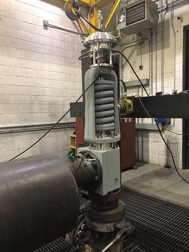
ASME-approved, in-service testing allows the use of lift assist devices attached to the spindle of the valve with adapters, along with other test apparatus to perform set pressure verification testing. The equipment shown in Figure 2 allows a carefully monitored lift force to be applied to the spindle of a PRV until the disc lifts off the seat. The process pressure and the lift force are known, enabling this type of a computer-driven system to determine the setpoint of the PRV, and confirm that it falls within tolerance. This specific type of lift assist equipment is known as a set pressure verification device (SPVD).
2. A portable lift assist, or auxiliary lift device, allows a PRV to be functionally tested without removing the valve from the process. Courtesy: Emerson
There are several other types of lift assist devices available to perform in-service set pressure verification testing, with varying degrees of effectiveness. For most applications, an SPVD is the preferred method of in-service testing.
A linear variable differential transformer (LVDT) is used to detect the earliest sign of valve stem movement, in the range of 0.020 inch, well below the point where the valve will go into full lift. At this time, force and pressure values are obtained, and the test is concluded to avoid wasteful discharge of the process media and minimize seat damage.
Perhaps the most important feature of an SPVD is a fully automated test execution system (Figure 3). This system incorporates an industrially hardened portable laptop computer running automated test protocols, including calibration and diagnostics. The computer can print out certified test results and be connected to up to five relief valves, simplifying and speeding test execution.
Some other types of lift devices are more manual and can only be operated by trained personnel, typically provided by the lift device vendor at considerable expense. However, a fully automated SPVD allows most plant technicians to perform PRV set pressure verification tests as needed. The most useful lift assist devices can be installed on a wide variety of PRVs, rather than just on those from specific manufacturers. Ideally, the lift device should be lightweight and easily adaptable to fit a wide range of relief valves.
Cost and scheduling benefits can be realized from self-test execution, and fully automated PRV set pressure testing also helps ensure consistent and accurate test results, regardless of personnel experience. SPVDs typically provide ASME-certified test results with a proven test accuracy of less than +/–1% error, significantly below the typical ASME test accuracy threshold of +/–3%.
SPVD is often the preferred choice to address a number of challenging PRV test issues. Some valves are very large or not easily removed, so an in-service test is clearly the least costly option (Figure 4). This can especially be true for large relief valves that are welded into the process piping.
4. Emerson’s Crosby SPVD is being used to perform an in-service test on this American Society of Mechanical Engineers (ASME) Section III Class 2 safety valve. Installation and testing of the SPVD does not restrict the PRV from operating should process conditions require the valve to open in service. Courtesy: Emerson
Inside nuclear power plants, many large PRVs are located within containment buildings, where access is extremely limited. For critical PRVs in these areas, SPVD lift assist heads and adapters can be permanently installed on the valves, with test cables routed outside the restricted zone and connected to a computer controller.
Since this type of lift device does not impact valve performance during normal operation or overpressure conditions, the PRV can still operate as necessary. Tests can be remotely performed from outside the containment building by simply plugging the cables into a test system and executing the test. Such an installation allows a plant to safely operate under normal conditions and test their critical PRVs on an as-needed basis, while avoiding any potential radiation exposure.
A well-designed lift assist device is a valuable addition to a plant’s PRV maintenance toolset. Every PRV is required to undergo regular in-service testing requirements as defined by the ASME Operation and Maintenance of Nuclear Power Plants code. The code permits use of lift assist devices to perform set pressure verification testing, which is particularly useful in situations where removing the valve from its installed position is not practical. The right lift assist device allows plant personnel to safely execute scheduled maintenance during outage events, or during operation in other cases, ensuring that critical PRVs are functioning per design with correctly adjusted setpoints.
A fully automated SPVD allows plant personnel to perform these tests consistently and accurately, freeing users to schedule and execute PRV tests, without the need for outside vendor involvement. This saves time and cost, and it removes dependence on a single vendor as a service provider. SPVD also provides a means for nuclear power plants to remotely test their critical relief valves, while avoiding exposure in containment areas.
If faced with a PRV testing challenge, plant personnel should consider lift-assist devices, such as an SPVD, as a potential solution. They meet ASME requirements for set pressure verification testing, and the fully automated operation of SPVD guarantees reliable test results, while providing many other benefits noted in this article.
—June DelGrossois the sales director for North America Nuclear and Navy at Emerson for its flow control products. She has worked for a variety of companies, filling roles such as Valve and Instrument Design Engineer, Product Engineering Manager, and Global Product Technical Leader.

(f) When operating conditions are changed, or additional boiler heating surface is installed, the valve capacity shall be increased, if necessary, to meet the new conditions and be in accordance with HG-400.l (e). The additional valves required, on account of changed conditions, may be installed on the outlet piping provided there is no intervening valve.
(a) Each hot water heating or supply boiler shall have at least one officially rated safety relief valve, of the automatic reseating type, identified with the V or HV Symbol, and set to relieve at or below the maximum allowable working pressure of the boiler.
(b) Hot water heating or supply boilers limited to a water temperature not in excess of 210°F (99°C) may have, in lieu of the valve(s) specified in (a) above, one or more officially rated temperature and pressure safety relief valves of the automatic reseating type identified with the HV symbol, and set to relieve at or below the maximum allowable working pressure of the boiler.
(c) When more than one safety relief valve is used on either hot water heating or hot water supply boilers, the additional valves shall be officially rated and may have a set pressure within a range not to exceed 6 psi (40 kPa) above the maximum allowable working pressure of the boiler up to and including 60 psi (400 kPa), and 5% for those having a maximum allowable working pressure exceeding 60 psi (400 kPa).
(d) No safety relief valve shall be smaller than NPS ¾ (DN 20) nor larger than NPS 4 (DN 100) except that boilers having a heat input not greater than 15,000 Btu/hr (4.4 kW) may be equipped with a rated safety relief valve of NPS ½ (DN 15).
(e) The required steam relieving capacity, in pounds per hour (kg/h), of the pressure relieving device or devices on a boiler shall be the greater of that determined by dividing the maximum output in Btu at the boiler nozzle obtained by the firing of any fuel for which the unit is installed by 1,000, or shall be determined on the basis of pounds (kg) of steam generated per hour per square foot (m2) of boiler heating surface as given in Table HG-400.1. For cast iron boilers constructed to the requirements of Part HC, the minimum valve capacity shall be determined by the maximum output method. In many cases a greater relieving capacity of valves will have to be provided than the minimum specified by these rules. In every case, the requirements of HG-400.2 (g) shall be met.
(f) When operating conditions are changed, or additional boiler heating surface is installed, the valve capacity shall be increased, if necessary, to meet the new conditions and shall be in accordance with HG-400,2(g). The additional valves required, on account of changed conditions, may be installed on the outlet piping provided there is no intervening valve.
(g) Safety relief valve capacity for each boiler with a single safety relief valve shall be such that, with the fuel burning equipment installed and operated at maximum capacity, the pressure cannot rise more than 10% above the maximum allowable working pressure. When more than one safety relief valve is used, the overpressure shall be limited to 10% above the set pressure of the highest set valve allowed by HG-400.2 (c).
(a)Steam to Hot Water Supply. When a hot water supply is heated indirectly by steam in a coil or pipe within the service limitations set forth in HG-101, the pressure of the steam used shall not exceed the safe working pressure of the hot water tank, and a safety relief valve at least NPS 1 (DN 25),set to relieve at or below the maximum allowable working pressure of the tank, shall be applied on the tank.
(b) High Temperature Water to Water Heat Exchanger.1 When high temperature water is circulated through the coils or tubes of a heat exchanger to warm water for space heating or hot water supply, within the service limitations set forth in HG-101, the heat exchanger shall be equipped with one or more officially rated safety relief valves that are identified with the V or HV Symbol, set to relieve at or below the maximum allowable working pressure of the heat exchanger, and of sufficient rated capacity to prevent the heat exchanger pressure from rising more than 10% above the maximum allowable working pressure of the vessel.
(c) High Temperature Water to Steam Heat Exchanger.1When high temperature water is circulated through the coils or tubes of a heat exchanger to generate low pressure steam, within the service limitations set forth in HG-101, the heat exchanger shall be equipped with one or more officially rated safety valves that are identified with the V or HV Symbol, set to relieve at a pressure not to exceed 15 psi (100 kPa), and of sufficient rated capacity to prevent the heat exchanger pressure from rising more than 5 psi (35 kPa) above the maximum allowable working pressure of the vessel. For heat exchangers requiring steam pressures greater than 15 psi (100 kPa), refer to Section I or Section VIII, Division 1.
(a) The inlet opening shall have an inside diameter approximately equal to, or greater than, the seat diameter. In no case shall the maximum opening through any part of the valve be less than ¼ in. (6 mm) in diameter or its equivalent area.
(c) O-rings or other packing devices when used on the stems of safety relief valves shall be so arranged as not to affect their operation or capacity.
(d) The design shall incorporate guiding arrangements necessary to insure consistent operation and tightness. Excessive lengths of guiding surfaces should be avoided. Bottom guided designs are not permitted on safety relief valves.
(f) Safety valves shall be spring loaded. The spring shall be designed so that the full lift spring compression shall be no greater than 80% of the nominal solid deflection. The permanent set of the spring (defined as the difference between the free height and height measured 10 min after the spring has been compressed solid three additional times after presetting at room temperature) shall not exceed 0.5% of the free height.
(h) A body drain below seat level shall be provided by the Manufacturer for all safety valves and safety relief valves, except that the body drain may be omitted when the valve seat is above the bottom of the inside diameter of the discharge piping. For valves exceeding NPS 2½ (DN 65) the drain hole or holes shall be tapped not less than NPS 3/8 (DN 10). For valves NPS 2½ (DN 65) or smaller, the drain hole shall not be less than ¼ in. (6 mm) in diameter. Body drain connections shall not be plugged during or after field installation. In safety relief valves of the diaphragm type, the space above the diaphragm shall be vented to prevent a buildup of pressure above the diaphragm. Safety relief valves of the diaphragm type shall be so designed that failure or deterioration of the diaphragm material will not impair the ability of the valve to relieve at the rated capacity.
(k) The set pressure tolerances, plus or minus, of safety valves shall not exceed 2 psi (15 kPa), and for safety relief valves shall not exceed 3 psi (20 kPa) for pressures up to and including 60 psig (400 kPa) and 5% for pressures above 60 psig (400 kPa).
(l) Safety valves shall be arranged so that they cannot be reset to relieve at a higher pressure than the maximum allowable working pressure of the boiler.
(e) Material for valve bodies and bonnets or their corresponding metallic pressure containing parts shall be listed in Section II,except that in cases where a manufacturer desires to make use of materials other than those listed in Section II, he shall establish and maintain specifications requiring equivalent control of chemical and physical properties and quality.
(a) A Manufacturer shall demonstrate to the satisfaction of an ASME designee that his manufacturing, production, and testing facilities and quality control procedures will insure close agreement between the performance of random production samples and the performance of those valves submitted for capacity certification.
(c) A Manufacturer may be granted permission to apply, the HV Code Symbol to production pressure relief valves capacity certified in accordance with HG-402.3 provided the following tests are successfully completed. This permission shall expire on the sixth anniversary of the date it is initially granted. The permission may be extended for 6 year periods if the following tests are successfully repeated within the 6 month period before expiration.
(1) Two sample production pressure relief valves of a size and capacity within the capability of an ASME accepted laboratory shall be selected by an ASME designee.
(2) Operational and capacity tests shall be conducted in the presence of an ASME designee at an ASME accepted laboratory. The valve Manufacturer shall be notified of the time of the test and may have representatives present to witness the test.
(3) Should any valve fail to relieve at or above its certified capacity or should it fail to meet performance requirements of this Section, the test shall be repeated at the rate of two replacement valves, selected in accordance with HG-401.3(c)(1), for each valve that failed.
(4) Failure of any of the replacement valves to meet the capacity or the performance requirements of this Section shall be cause for revocation within 60 days of the authorization to use the Code Symbol on that particular type of valve. During this period, the Manufacturer shall demonstrate the cause of such deficiency and the action taken to guard against future occurrence, and the requirements of HG-401.3(c) above shall apply.
(d) Safety valves shall be sealed in a manner to prevent the valve from being taken apart without breaking the seal. Safety relief valves shall be set and sealed so that they cannot be reset without breaking the seal.
(a) Every safety valve shall be tested to demonstrate its popping point, blowdown, and tightness. Every safety relief valve shall be tested to demonstrate its opening point and tightness. Safety valves shall be tested on steam or air and safety relief valves on water, steam, or air. When the blowdown is nonadjustable, the blowdown test may be performed on a sampling basis.
(c) Testing time on safety valves shall be sufficient, depending on size and design, to insure that test results are repeatable and representative of field performance.
HG-401.5 Design Requirements. At the time of the submission of valves for capacity certification, or testing in accordance with this Section, the ASME Designee has the authority to review the design for conformity with the requirements of this Section, and to reject or require modification of designs that do not conform, prior to capacity testing.
HG-402.1 Valve Markings. Each safety or safety-relief valve shall be plainly marked with the required data by the Manufacturer in such a way that the markings will not be obliterated in service. The markings shall be stamped, etched, impressed, or cast on the valve or on a nameplate, which shall be securely fastened to the valve.
(6) year built or, alternatively, a coding may be marked on the valves such that the valve Manufacturer can identify the year the valve was assembled and tested, and
HG-402.2 Authorization to Use ASME Stamp.Each safety valve to which the Code Symbol (Fig. HG-402) is to be applied shall be produced by a Manufacturer and/or Assembler who is in possession of a valid Certificate of Authorization. (See HG-540.) For all valves to be stamped with the HV Symbol, a Certified Individual (CI) shall provide oversight to ensure that the use of the “HV" Code symbol on a safety valve or safety relief valve is in accordance with this Section and that the use of the “HV" Code symbol is documented on a Certificate of Conformance Form, HV-1.
(1) verify that each item to which the Code Symbol is applied meets all applicable requirements of this Section and has a current capacity certification for the “HV" symbol
(2) The Manufacturer"s written quality control program shall include requirements for completion of Certificates of Conformance forms and retention by the Manufacturer for a minimum of 5 years.
HG-402.3 Determination of Capacity to Be Stamped on Valves. The Manufacturer of the valves that are to be stamped with the Code symbol shall submit valves for testing to a place where adequate equipment and personnel are available to conduct pressure and relieving-capacity tests which shall be made in the presence of and certified by an authorized observer. The place, personnel, and authorized observer shall be approved by the Boiler and Pressure Vessel Committee. The valves shall be tested in one of the following three methods.
(a) Coefficient Method. Tests shall be made to determine the lift, popping, and blowdown pressures, and the capacity of at least three valves each of three representative sizes (a total of nine valves). Each valve of a given size shall be set at a different pressure. However, safety valves for steam boilers shall have all nine valves set at 15 psig (100 kPa). A coefficient shall be established for each test as follows:


 8613371530291