
asme safety valve testing requirements free sample
Boiler explosions have been responsible for widespread damage to companies throughout the years, and that’s why today’s boilers are equipped with safety valves and/or relief valves. Boiler safety valves are designed to prevent excess pressure, which is usually responsible for those devastating explosions. That said, to ensure that boiler safety valves are working properly and providing adequate protection, they must meet regulatory specifications and require ongoing maintenance and periodic testing. Without these precautions, malfunctioning safety valves may fail, resulting in potentially disastrous consequences.
Boiler safety valves are activated by upstream pressure. If the pressure exceeds a defined threshold, the valve activates and automatically releases pressure. Typically used for gas or vapor service, boiler safety valves pop fully open once a pressure threshold is reached and remain open until the boiler pressure reaches a pre-defined, safe lower pressure.
Boiler relief valves serve the same purpose – automatically lowering boiler pressure – but they function a bit differently than safety valves. A relief valve doesn’t open fully when pressure exceeds a defined threshold; instead, it opens gradually when the pressure threshold is exceeded and closes gradually until the lower, safe threshold is reached. Boiler relief valves are typically used for liquid service.
There are also devices known as “safety relief valves” which have the characteristics of both types discussed above. Safety relief valves can be used for either liquid or gas or vapor service.
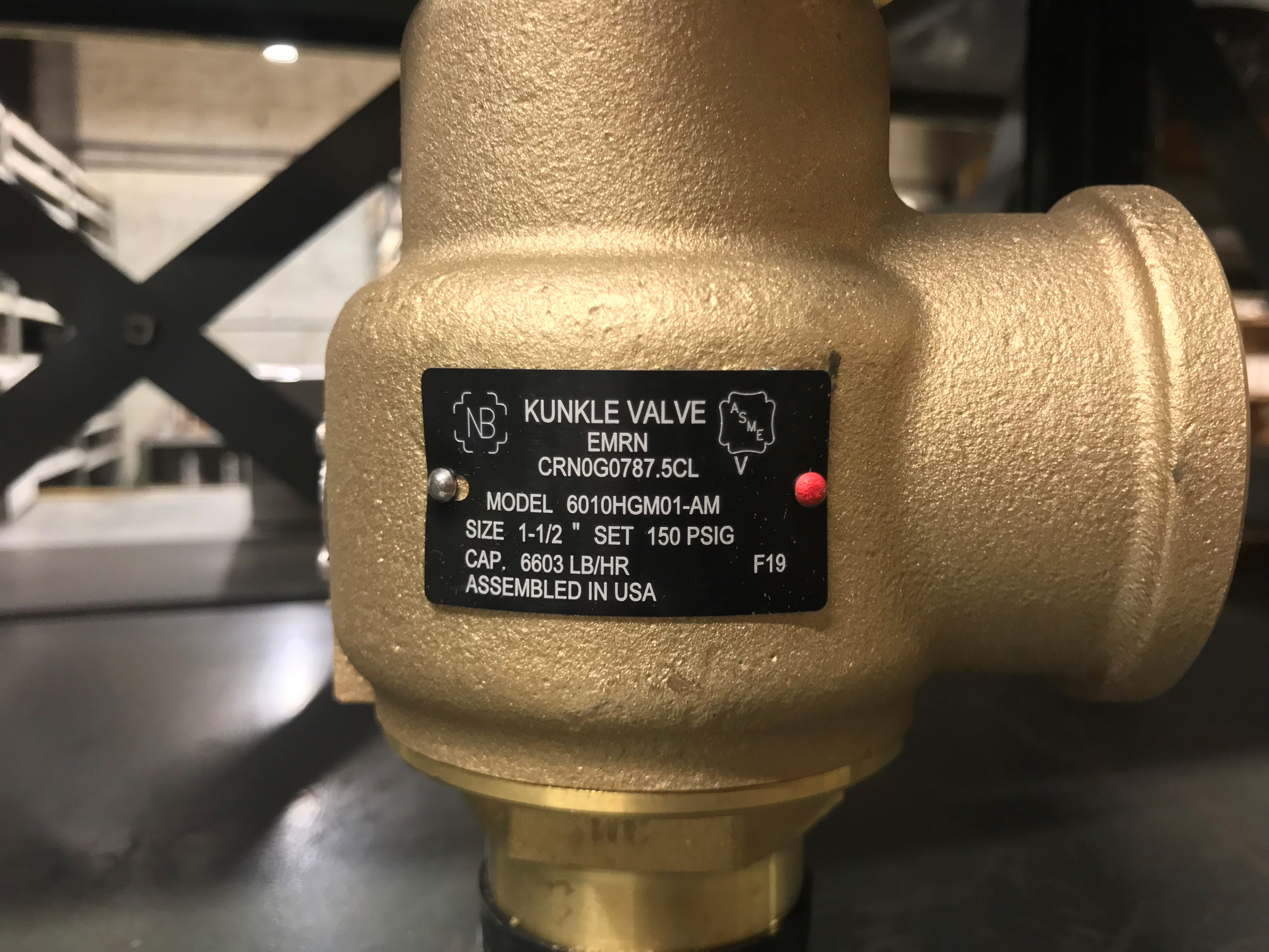
Nameplates must be fastened securely and permanently to the safety valve and remain readable throughout the lifespan of the valve, so durability is key.
The National Board of Boiler and Pressure Vessel Inspectors offers guidance and recommendations on boiler and pressure vessel safety rules and regulations. However, most individual states set forth their own rules and regulations, and while they may be similar across states, it’s important to ensure that your boiler safety valves meet all state and local regulatory requirements.
The National Board published NB-131, Recommended Boiler and Pressure Vessel Safety Legislation, and NB-132, Recommended Administrative Boiler and Pressure Vessel Safety Rules and Regulationsin order to provide guidance and encourage the development of crucial safety laws in jurisdictions that currently have no laws in place for the “proper construction, installation, inspection, operation, maintenance, alterations, and repairs” necessary to protect workers and the public from dangerous boiler and pressure vessel explosions that may occur without these safeguards in place.
The documents are meant to be used as a guide for developing local laws and regulations and also may be used to update a jurisdiction’s existing requirements. As such, they’re intended to be modifiable to meet any jurisdiction’s local conditions.
The American Society of Mechanical Engineers (ASME) governs the code that establishes guidelines and requirements for safety valves. Note that it’s up to plant personnel to familiarize themselves with the requirements and understand which parts of the code apply to specific parts of the plant’s steam systems.
High steam capacity requirements, physical or economic constraints may make the use of a single safety valve impossible. In these cases, using multiple safety valves on the same system is considered an acceptable practice, provided that proper sizing and installation requirements are met – including an appropriately sized vent pipe that accounts for the total steam venting capacity of all valves when open at the same time.
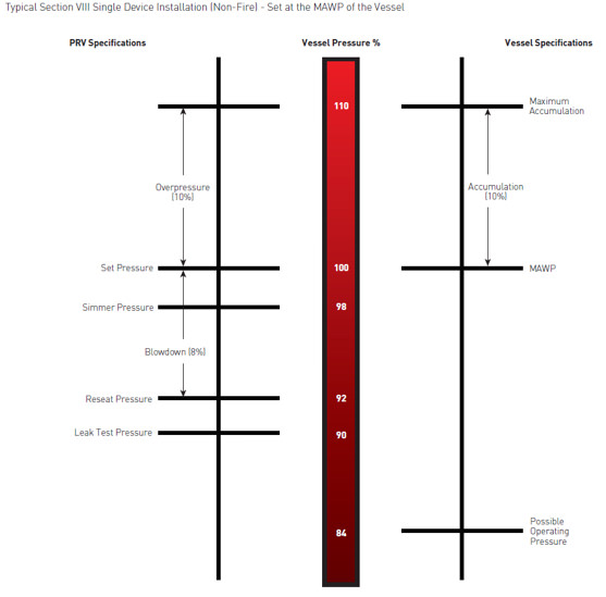
The lowest rating (MAWP or maximum allowable working pressure) should always be used among all safety devices within a system, including boilers, pressure vessels, and equipment piping systems, to determine the safety valve set pressure.
Avoid isolating safety valves from the system, such as by installing intervening shut-off valves located between the steam component or system and the inlet.
Contact the valve supplier immediately for any safety valve with a broken wire seal, as this indicates that the valve is unsafe for use. Safety valves are sealed and certified in order to prevent tampering that can prevent proper function.
Avoid attaching vent discharge piping directly to a safety valve, which may place unnecessary weight and additional stress on the valve, altering the set pressure.
Safety is of the utmost importance when dealing with pressure relief valves. The valve is designed to limit system pressure, and it is critical that they remain in working order to prevent an explosion. Explosions have caused far too much damage in companies over the years, and though pressurized tanks and vessels are equipped with pressure relief vales to enhance safety, they can fail and result in disaster.
That’s also why knowing the correct way to test the valves is important. Ongoing maintenance and periodic testing of pressurized tanks and vessels and their pressure relief valves keeps them in working order and keep employees and their work environments safe. Pressure relief valves must be in good condition in order to automatically lower tank and vessel pressure; working valves open slowly when the pressure gets high enough to exceed the pressure threshold and then closes slowly until the unit reaches the low, safe threshold. To ensure the pressure relief valve is in good working condition, employees must follow best practices for testing them including:
If you consider testing pressure relief valves a maintenance task, you’ll be more likely to carry out regular testing and ensure the safety of your organization and the longevity of your
It’s important to note, however, that the American Society of Mechanical Engineers (ASME) and National Board Inspection Code (NBIC), as well as state and local jurisdictions, may set requirements for testing frequency. Companies are responsible for checking with these organizations to become familiar with the testing requirements. Consider the following NBIC recommendations on the frequency for testing relief valves:
High-pressure steam boilers 400 psi and greater – pressure test to verify nameplate set pressure every three years or as determined by operating experience as verified by testing history
High-temperature hot water boilers (greater than 160 psi and/or 250 degrees Fahrenheit) – pressure test annually to verify nameplate set pressure. For safety reasons, removal and testing on a test bench is recommended
When testing the pressure relief valve, raise and lower the test lever several times. The lever will come away from the brass stem and allow hot water to come out of the end of the drainpipe. The water should flow through the pipe, and then you should turn down the pressure to stop the leak, replace the lever, and then increase the pressure.
One of the most common problems you can address with regular testing is the buildup of mineral salt, rust, and corrosion. When buildup occurs, the valve will become non-operational; the result can be an explosion. Regular testing helps you discover these issues sooner so you can combat them and keep your boiler and valve functioning properly. If no water flows through the pipe, or if there is a trickle instead of a rush of water, look for debris that is preventing the valve from seating properly. You may be able to operate the test lever a few times to correct the issue. You will need to replace the valve if this test fails.
When testing relief valves, keep in mind that they have two basic functions. First, they will pop off when the pressure exceeds its safety threshold. The valve will pop off and open to exhaust the excess pressure until the tank’s pressure decreases to reach the set minimum pressure. After this blowdown process occurs, the valve should reset and automatically close. One important testing safety measure is to use a pressure indicator with a full-scale range higher than the pop-off pressure.
Thus, you need to be aware of the pop-off pressure point of whatever tank or vessel you test. You always should remain within the pressure limits of the test stand and ensure the test stand is assembled properly and proof pressure tested. Then, take steps to ensure the escaping pressure from the valve is directed away from the operator and that everyone involved in the test uses safety shields and wears safety eye protection.
After discharge – Because pressure relief valves are designed to open automatically to relieve pressure in your system and then close, they may be able to open and close multiple times during normal operation and testing. However, when a valve opens, debris may get into the valve seat and prevent the valve from closing properly. After discharge, check the valve for leakage. If the leakage exceeds the original settings, you need to repair the valve.
According to local jurisdictional requirements – Regulations are in place for various locations and industries that stipulate how long valves may operate before needing to be repair or replaced. State inspectors may require valves to be disassembled, inspected, repaired, and tested every five years, for instance. If you have smaller valves and applications, you can test the valve by lifting the test lever. However, you should do this approximately once a year. It’s important to note that ASME UG136A Section 3 requires valves to have a minimum of 75% operating pressure versus the set pressure of the valve for hand lifting to be performed for these types of tests.
Depending on their service and application– The service and application of a valve affect its lifespan. Valves used for clean service like steam typically last at least 20 years if they are not operated too close to the set point and are part of a preventive maintenance program. Conversely, valves used for services such as acid service, those that are operated too close to the set point, and those exposed to dirt or debris need to be replaced more often.
Pressure relief valves serve a critical role in protecting organizations and employees from explosions. Knowing how and when to test and repair or replace them is essential.
Pressure relief valves (PRVs) are a critical line of defense for pressure vessel protection in the power industry. Generating facilities worldwide depend upon these devices to sense and quickly relieve overpressure conditions to avoid catastrophic damage during process upsets. To ensure these valves will perform as expected, mechanical engineering regulatory bodies mandate the valves be tested on a routine basis.
Some installations make the option of pulling the valve for servicing and testing very difficult. This is particularly true for large size valves, and in the nuclear power industry where valves may be located inside containment areas, making valve access particularly problematic. Fortunately, there is another approved method of testing relief valves for this situation, and this alternative solution is the subject of this article.
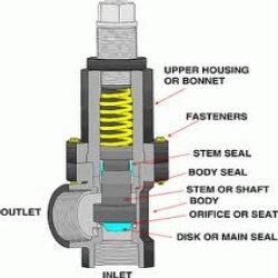
PRVs are relatively, but deceptively, simple devices. They consist of an inlet nozzle attached to the process, which is blocked by a disc held tightly on the nozzle seat (Figure 1). The disc is kept closed by a spring, with adjustments carefully made to dial in the setpoint of the valve.
1. A pressure relief valve (PRV) protects equipment by automatically opening to vent process media when the pressure in the inlet nozzle overcomes the downward force of the spring. Courtesy: Emerson
When the process reaches set pressure, the upward force of the process media offsets the downward force of the spring and the disc lifts off the seat. The process media is relieved through the valve outlet until pressure falls below the setpoint. At this point, the downward force of the spring overcomes the upward force of the process media, and the valve closes.
To ensure the PRV will function when called into action, the American Society of Mechanical Engineers (ASME) mandates relief valves be functionally checked on a routine basis. Typically, a plant will pull smaller valves from their installed position during process outages, and then inspect and test them in a shop environment to confirm they will function as desired and open at the proper pressure setpoint. However, this method of testing is not so easily achieved in certain cases.
Some relief valves are very large and/or located in difficult to reach areas. Others are welded into place and not easily removed from the process. Valves inside nuclear containment areas are particularly troublesome since access to these areas is usually restricted, with strict adherence to extensive protocols required for entry.
To handle these challenging situations, ASME provides alternate means of testing relief valves, as documented in ASME Performance Test Code (PTC) 25 Pressure Relief Devices. These test methods include in-service testing, which allows the plant to functionally test the relief valve without removing it from the process. This in-situ test method can be quite accurate and effective, but only if it is performed correctly with the right equipment.
Service and testing of PRVs is typically performed during regular maintenance outages as defined by ASME guidelines. Operating pressures and temperatures are brought down to levels conducive for servicing, and the PRVs are tested by maintenance technicians. For this type of in-service, or in-situ testing, lift assist devices are used in conjunction with these lower system pressures to verify the PRV will operate at the setpoint, within allowable tolerances.
ASME-approved, in-service testing allows the use of lift assist devices attached to the spindle of the valve with adapters, along with other test apparatus to perform set pressure verification testing. The equipment shown in Figure 2 allows a carefully monitored lift force to be applied to the spindle of a PRV until the disc lifts off the seat. The process pressure and the lift force are known, enabling this type of a computer-driven system to determine the setpoint of the PRV, and confirm that it falls within tolerance. This specific type of lift assist equipment is known as a set pressure verification device (SPVD).
2. A portable lift assist, or auxiliary lift device, allows a PRV to be functionally tested without removing the valve from the process. Courtesy: Emerson
There are several other types of lift assist devices available to perform in-service set pressure verification testing, with varying degrees of effectiveness. For most applications, an SPVD is the preferred method of in-service testing.
A linear variable differential transformer (LVDT) is used to detect the earliest sign of valve stem movement, in the range of 0.020 inch, well below the point where the valve will go into full lift. At this time, force and pressure values are obtained, and the test is concluded to avoid wasteful discharge of the process media and minimize seat damage.
Perhaps the most important feature of an SPVD is a fully automated test execution system (Figure 3). This system incorporates an industrially hardened portable laptop computer running automated test protocols, including calibration and diagnostics. The computer can print out certified test results and be connected to up to five relief valves, simplifying and speeding test execution.
Some other types of lift devices are more manual and can only be operated by trained personnel, typically provided by the lift device vendor at considerable expense. However, a fully automated SPVD allows most plant technicians to perform PRV set pressure verification tests as needed. The most useful lift assist devices can be installed on a wide variety of PRVs, rather than just on those from specific manufacturers. Ideally, the lift device should be lightweight and easily adaptable to fit a wide range of relief valves.
Cost and scheduling benefits can be realized from self-test execution, and fully automated PRV set pressure testing also helps ensure consistent and accurate test results, regardless of personnel experience. SPVDs typically provide ASME-certified test results with a proven test accuracy of less than +/–1% error, significantly below the typical ASME test accuracy threshold of +/–3%.
SPVD is often the preferred choice to address a number of challenging PRV test issues. Some valves are very large or not easily removed, so an in-service test is clearly the least costly option (Figure 4). This can especially be true for large relief valves that are welded into the process piping.
4. Emerson’s Crosby SPVD is being used to perform an in-service test on this American Society of Mechanical Engineers (ASME) Section III Class 2 safety valve. Installation and testing of the SPVD does not restrict the PRV from operating should process conditions require the valve to open in service. Courtesy: Emerson
Inside nuclear power plants, many large PRVs are located within containment buildings, where access is extremely limited. For critical PRVs in these areas, SPVD lift assist heads and adapters can be permanently installed on the valves, with test cables routed outside the restricted zone and connected to a computer controller.
Since this type of lift device does not impact valve performance during normal operation or overpressure conditions, the PRV can still operate as necessary. Tests can be remotely performed from outside the containment building by simply plugging the cables into a test system and executing the test. Such an installation allows a plant to safely operate under normal conditions and test their critical PRVs on an as-needed basis, while avoiding any potential radiation exposure.
A well-designed lift assist device is a valuable addition to a plant’s PRV maintenance toolset. Every PRV is required to undergo regular in-service testing requirements as defined by the ASME Operation and Maintenance of Nuclear Power Plants code. The code permits use of lift assist devices to perform set pressure verification testing, which is particularly useful in situations where removing the valve from its installed position is not practical. The right lift assist device allows plant personnel to safely execute scheduled maintenance during outage events, or during operation in other cases, ensuring that critical PRVs are functioning per design with correctly adjusted setpoints.
A fully automated SPVD allows plant personnel to perform these tests consistently and accurately, freeing users to schedule and execute PRV tests, without the need for outside vendor involvement. This saves time and cost, and it removes dependence on a single vendor as a service provider. SPVD also provides a means for nuclear power plants to remotely test their critical relief valves, while avoiding exposure in containment areas.
If faced with a PRV testing challenge, plant personnel should consider lift-assist devices, such as an SPVD, as a potential solution. They meet ASME requirements for set pressure verification testing, and the fully automated operation of SPVD guarantees reliable test results, while providing many other benefits noted in this article.
—June DelGrossois the sales director for North America Nuclear and Navy at Emerson for its flow control products. She has worked for a variety of companies, filling roles such as Valve and Instrument Design Engineer, Product Engineering Manager, and Global Product Technical Leader.


 8613371530291