
asme safety valve testing requirements brands

The ASME Pressure Relief Device (PRD) Testing Laboratory Accreditation Program accredits manufacturers of pressure relief devices and assemblers of pressure relief valves. It is a hybrid program in that it accredits both the manufacturer and specific personnel within the manufacturing organization (the authorized observer). It is operated in conjunction with The National Board of Boiler and Pressure Vessel Inspectors. Therefore, a manufacturer seeking this accreditation submits an application directly to ASME, but details about the program and review process can be found on The National Board of Boiler and Pressure Vessel Inspector"s website.
Companies that have been accredited through the PRD Accreditation Program are operating in accordance with the applicable rules of the associated ASME BPVC, the ASME PTC-25 standard, "Pressure Relief Devices," as well as one of the standards of construction accepted by The National Board of Boiler and Pressure Vessel Inspectors.
The primary role of a safety relief valve is to prevent over-pressure situations in pressurized vessels or systems. If the tank’s relief valve fails, it can lead to an accident that destroys property, life, or landscape.
The National Board of Boiler and Pressure Vessel Inspectors is one of the governing bodies for the testing and/or repair of ASME Safety Relief Valves.
You, as the owner of the valve, can test it, but it must be done in accordance with the National Board Inspection Code and your state’s and/or local regulations.
Based on the National Board Code, which bases their inspection intervals on what type of service the valve is used for, the following intervals are suggested:
Also, keep in mind that this piping should be oriented so that no liquid relieved through this piping can flow back and rest on the ASME safety relief valve’s outlet port.
The ASME relief valves are set to fully open at its “set” pressure but will begin to partially open before then – normally at 10% below its set pressure.
If your valve is allowed to do this, trash and/or corrosion can set in over time which could prevent the valve from either closing completely or from fully opening, either of which is not a favorable solution.
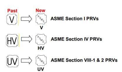
The National Board’s goal is to maintain the integrity of the National Board marks and symbols (NB,VR, andT/O) and the ASME Certification mark with V ,UV, UD, HV, and NV designators. By doing so, we make it possible for National Board members to rely on the presence of these marks in their efforts to protect the general public.
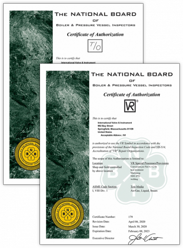
The National Board offers the Certificate of Authorization and VR Stamp for the repair of pressure relief valves. Requirements are included in the current mandatory edition of the National Board Inspection Code(NBIC), Part 4, and NB-514, Accreditation of VR Repair Organizations.
The National Board offers the Certificate of Authorization for use of the T/O mark which indicates accreditation as a pressure relief valve Testing Organization. The program includes provisions for minor adjustments to restore valve performance. Requirements are based upon the current mandatory edition of the National Board Inspection Code(NBIC), Part 2, Part 4, and NB-528, Accreditation of T/O Test Only Organizations.
Representatives from the National Board are assigned to visit company sites to select production sample valves for testing at National Board- and ASME- accepted labs.
Boiler explosions have been responsible for widespread damage to companies throughout the years, and that’s why today’s boilers are equipped with safety valves and/or relief valves. Boiler safety valves are designed to prevent excess pressure, which is usually responsible for those devastating explosions. That said, to ensure that boiler safety valves are working properly and providing adequate protection, they must meet regulatory specifications and require ongoing maintenance and periodic testing. Without these precautions, malfunctioning safety valves may fail, resulting in potentially disastrous consequences.
Boiler safety valves are activated by upstream pressure. If the pressure exceeds a defined threshold, the valve activates and automatically releases pressure. Typically used for gas or vapor service, boiler safety valves pop fully open once a pressure threshold is reached and remain open until the boiler pressure reaches a pre-defined, safe lower pressure.
Boiler relief valves serve the same purpose – automatically lowering boiler pressure – but they function a bit differently than safety valves. A relief valve doesn’t open fully when pressure exceeds a defined threshold; instead, it opens gradually when the pressure threshold is exceeded and closes gradually until the lower, safe threshold is reached. Boiler relief valves are typically used for liquid service.
There are also devices known as “safety relief valves” which have the characteristics of both types discussed above. Safety relief valves can be used for either liquid or gas or vapor service.
Nameplates must be fastened securely and permanently to the safety valve and remain readable throughout the lifespan of the valve, so durability is key.
The National Board of Boiler and Pressure Vessel Inspectors offers guidance and recommendations on boiler and pressure vessel safety rules and regulations. However, most individual states set forth their own rules and regulations, and while they may be similar across states, it’s important to ensure that your boiler safety valves meet all state and local regulatory requirements.
The National Board published NB-131, Recommended Boiler and Pressure Vessel Safety Legislation, and NB-132, Recommended Administrative Boiler and Pressure Vessel Safety Rules and Regulationsin order to provide guidance and encourage the development of crucial safety laws in jurisdictions that currently have no laws in place for the “proper construction, installation, inspection, operation, maintenance, alterations, and repairs” necessary to protect workers and the public from dangerous boiler and pressure vessel explosions that may occur without these safeguards in place.
The documents are meant to be used as a guide for developing local laws and regulations and also may be used to update a jurisdiction’s existing requirements. As such, they’re intended to be modifiable to meet any jurisdiction’s local conditions.
The American Society of Mechanical Engineers (ASME) governs the code that establishes guidelines and requirements for safety valves. Note that it’s up to plant personnel to familiarize themselves with the requirements and understand which parts of the code apply to specific parts of the plant’s steam systems.
High steam capacity requirements, physical or economic constraints may make the use of a single safety valve impossible. In these cases, using multiple safety valves on the same system is considered an acceptable practice, provided that proper sizing and installation requirements are met – including an appropriately sized vent pipe that accounts for the total steam venting capacity of all valves when open at the same time.
The lowest rating (MAWP or maximum allowable working pressure) should always be used among all safety devices within a system, including boilers, pressure vessels, and equipment piping systems, to determine the safety valve set pressure.
Avoid isolating safety valves from the system, such as by installing intervening shut-off valves located between the steam component or system and the inlet.
Contact the valve supplier immediately for any safety valve with a broken wire seal, as this indicates that the valve is unsafe for use. Safety valves are sealed and certified in order to prevent tampering that can prevent proper function.
Avoid attaching vent discharge piping directly to a safety valve, which may place unnecessary weight and additional stress on the valve, altering the set pressure.
A relief valve is one of the most crucial pressured system components and often the last device to prevent catastrophic failures in high-pressured systems. That is why it is essential that relief valves are always certified and should work at all times.
Relief valves are pressure valves that are designed to open at a preset pressure and discharge fluid until the pressure drops to a safe and acceptable level. This means the relief valve is the last resort that releases pressure when other components in the system have failed to control the pressure.
Safety is of paramount importance when it comes to dealing with relief valves. So, it’s critical for industries to make sure the valves are working as designed.
The only way to do that is through periodic inspection and standardized testing. The standards about relief valves and associated assemblies like boilers and pressured vessels are regulated by ASME, API, OSHA, National Board, and individual State codes.
Standard requirements include periodic inspection, testing, and recertification. Certification assures that a valve’s condition and performance are essentially equal to that of a new valve.
Though ASME is the leading organization governing pressured systems’ standards and codes, the body itself does not certify the valves. Certification and recertification of relief valves are done by the National Board (NB).
Performing periodic testing on relief valves is the best practice to ensure that the valves are in good working condition and the employees and work environment is safe.
The above recommendations constitute correct inspecting and testing practices for efficient Relief Valve operations and, ultimately, a safe working environment. However, one crucial safety measure is to use a pressure indicator with a full-scale range higher than the valve’s relief pressure.
In fact, we believe proper valve inspection, testing, and maintenance is the best investment you make in the safety and security of your company and employees.
Our valve experts focus on getting your old valves tested and recertified for safe use. On top of that, we evaluate the repair condition of every valve and recommend the right solution to manage your equipment better.
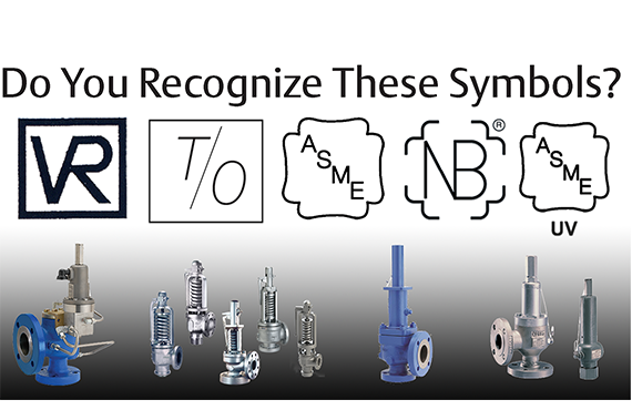
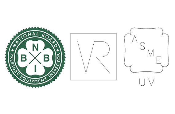
The improper installation of pressure relief devices can have dire consequences, causing unnecessary safety risks, and delaying operations while they are replaced or repaired. PRVs are typically one of the last lines of defense in an upset condition. To ensure that PRVs relieve and flow properly, the ASME and the National Board certify all PRV assembly programs, testing facilities, and even technicians. When you see marks and symbols on your pressure relief devices, it means that your device is certified safe because it came from a National Board and/or ASME certified organization.
The five symbols in the above graphic above are issued by the ASME and National Board. There are others, and you may see a few different variations from time to time. Each of them denotes a specific certification:
ASME Boiler and Pressure Vessel Code Certificate of Authorization Program The American Society of Mechanical Engineers offers Certificates of Authorization for the construction of new pressure-retaining equipment to various sections of the ASME Boiler and Pressure Vessel Code – Section I; IV; VIII, Divisions 1, 2, & 3; X; and XII. A
The ASME Single Certification mark indicates that an organization has followed all aspects of the ASME codes and standards, meeting all requirements of the Conformity Assessment certification program. The ASME certification mark is stamped onto devices, paired with one of 8 designators from the National Board: V, UV, UV3, UD, HV, NV, TV, depending on which program they’ve completed. For example, at Vinson Process Controls, we are UV Assembly certified, meaning we successfully completed the National Board’s UV Assembly certification program. Because we are a certified PRV assembler, our customers know that the pressure relief devices they receive from us are compliant with the ASME Boiler and Pressure Vessel Codes (BPVCs). The mark for a UV assembly certified company has the ASME single certification mark paired with the UV designator from the national board.
The simple answer? Safety. However, there’s a bit more to safety than you might think. In order to ensure safe operation, organizations like the ASME and National Board set firm standards and require the completion of specific programs to attain certification. These programs are rigorous, and the UV Assembly Program is no exception. It’s designed to be very stringent, as it ensures consistency in the capabilities and functionality of all components in the PRV assembly process. Ideally, a PRV should be procured from a certified assembler that is also able to test and repair the device if necessary. Unfortunately, this is a tall order that not all suppliers are able to.
Vinson Process Controls has the capabilities and credentials required to assemble, test and repair pressure relief devices. In order to better serve our customers, we earned the certifications for the UV (assembly program), VR (valve repair) and T/O (testing only) certifications from the ASME and the National Board. We take the guesswork out of PRV procuring and maintenance so that our customers can relax and reap the benefits.
As a UV-certified assembler, Vinson has invested in stocking Anderson Greenwood™ and Crosby™ relief valves for faster lead times. We have a wide range of options for our customers, including same-day service, when required. The vast majority of Vinson’s relief valve inventory is in the portable 81P valves and pilot operated valves. Apart from the combined inventory we share with Emerson, we also have access to shared inventory across all 21 of Emerson’s Impact Partners. We are proud to say that all valves assembled in our Carrolton Valve Center have met or exceeded expected shipping dates.
In addition to faster lead times, our customers can maintain confidence that the products shipping from Vinson are of the samequality as those shipping directly from Emerson’s factory. The ASME, the National Board and Emerson audit all shops, quality control processes, techniques, and valves, before and after awarding certifications. Vinson will continue to receive audits to ensure that we are meeting or exceeding expectations over time. Our adhesion to our quality control manual means that all valves assembled by Vinson have the same factory warranty as if they were assembled in Emerson’s production line.
As a part of the Emerson Impact Partner Network, Vinson is one of the primary points of contact for direct sales of Anderson Greenwood™ and Crosby™. We are a certified UV assembler, also offering valve repair and testing services. We can offer you quotes for both repair and replacement options. Because of this unique status, Vinson can offer competitive pricing.
Vinson is proud to be an ASME and National Board UV and VR certified supplier. We are excited about our ability to offer our customers flexible delivery and quality products, all at a competitive rate. Our partnership with Emerson™ and the Emerson Impact Partner network enables us to provide continued support for our clients, no matter the complexity of their application needs. Contact us for assistance with your next project. We’re here to help and we’d love to hear from you!
**Update to this article, June 7, 2022 : If you found this article helpful, here is a link to another article I recently found that does a nice job explaining the topic: ENGINEERS BEWARE: API vs ASME Relief Valve Orifice Size – Petro Chem Engineering (petrochemengg.com)
NOTE: this article is written to an audience that is familiar with PSVs, PSV sizing, and API and ASME standards at a basic level. I initially wrote this article in early 2017, and due to some great input and questions made significant revisions to increase clarity in mid-2018. I hope it is helpful to you, please send me a message with any comments/questions!
If you"ve ever sized/selected a Pressure Safety-Relief Valve (PSV) using vendor sizing programs or good-old hand calculations, you"ve probably run into a very strange anomaly: Why does a PSV orifice size change between American Petroleum Institute (API) and American Society of Mechanical Engineers (ASME) data sets? What is an "effective" orifice area? How do I know which standard to use when selecting a PSV?
Usually, this issue is one of curiosity and doesn"t affect the end result of what valve is chosen. Common practice is to default to API sizing equations and parameters, and only use ASME data sets for situations outside of the API letter-designations. But what if I told you that approach is likely causing you to oversize about 10% of your PSVs and their respective piping systems?
Most of the time simply using API data sets is fine. And I should note that this is a conservative approach, so you won’t make a mistake doing this. But did you know that PSVs are certified to ASME capacities, not API? And did you know those ASME capacities are nearly always higher than the API ones? I’m guessing you don’t, because there are very few resources available that speak to this topic. I’ve found it common for engineers to understand API 520 quite well, but have a very limited working knowledge of how the ASME BPVC comes into play.
Too often, we leave that third part out of the process, and simply calculate relief loads and select valves using API techniques, without ever checking our selection against certified ASME data. Proper application of these standards is the first key point of this article:
Initial sizing and valve selection is done using API equations, and final valve selection and certification is done using ASME-certified coefficients and capacities.
When sizing a PSV, the sizing equations are always API 520. When a PSV is certified, it is always certified to ASME BPVC (whether one “selects” ASME certification or not!) It"s important to remember that the ASME BPVC is the "code", the standard to which we must design. API 520/526 are "recommended practices" which were developed to give engineers a tool to meet the ASME requirements. Another way to look at it: ASME BPVC sets the goal, API 520/526 provide the instructions, and ASME has the final say.
The BPVC is an enormous code, and not reviewed in detail here. On the subject of PSVs, it basically says that a PSV must be capable of relieving the required load, and it must be tested in a specific manner to be certified to do so. If a valve is tested per the specific directions in the BPVC, it will be ASME certified and receive an ASME UV stamp.
The first thing API does is attempt to standardize physical PSV sizes and design, and it does so in API RP 526, which is targeted at PSV manufacturers. API provides pre-defined valve sizes, with letter designations D through T (API 526). It also defines other details directed toward valve manufacturers (such as temperature ratings). All of this is intended as minimum design standards, and manufacturers are free to exceed these parameters as they wish.
The second thing API does is provide standardized equations and parameters to use when trying to figure out just what size of a PSV one needs for a particular scenario. The equations account for design parameters that ASME doesn"t speak to, such as specific fluid properties, backpressures, critical flow, two-phase flow, and many other aspects of fluid dynamics that will affect the ability of a particular valve to relieve a required load.
API sizing equations are by nature theoretical, standardized, and use default or "dummy" values for several sizing parameters that may or may not reflect the actual values for any specific valve.
API RP 520 very clearly talks about this, and emphasizes that the intended use of its equations is to determine a preliminary valve size, which should be verified with actual data. API intends PSV sizing to be a two-step process, but we are often unaware of this because we (gasp) don’t read the full standard, and/or rely solely on vendor sizing software that hides the iteration from us. See API 520, part 1, section 5.2 for further explanation.
When valves are built, they are built to the API RP 526 standard, however, as one might imagine, when valves are actually tested and certified, the results don’t match up identically to the theoretical values that were calculated. This is where API and ASME intersect; we switch from calculations (API) which were used as a basis to design the valve, to actual empirical data (ASME) to certify the valve. When a valve manufacturer gets the UV code stamp that certifies the valve orifice size and capacity, it is based on actual test results, not API sizing standards. And ASME (which came first) does not have tiered letter designations. The typical D, E, F, etc. sizes we refer to are strictly an API tool, and ASME’s capacity certifications are completely independent of them!
2. They test the final product according to ASME BPVC, and get a result that equates to an effective orifice area of 4.90in2. This is its ASME effective area.
3. A third-party Engineer (you), trying to select a PSV, runs a sizing calculation using API 520 equations on ABC Valve Company"s sizing software, gets a result that requires 4.66in2 to relieve the load, and is now thoroughly confused on what size valve to select.
If one selects the API data set on the sizing software in this example, it will automatically eliminate N-orifice valves as an option, and bump the user up to a P-orifice. However, if one simply selects the ASME data set, the N-orifice valve magically reappears as an option. How can this be? Will the N-orifice work or not?
The short answer is yes, it is certified to an actual area of 4.90in2. So the “N” orifice for this specific PSV will work, and is certified to do so, in this application. Remember: use API to get you close, and ASME to confirm the final answer.
Digest that for a moment. If you’ve sized and purchased more than a dozen PSVs, chances are you have inadvertently selected a PSV a full size larger than you needed to, in a situation much like our example, simply because you chose a PSV based on its API “rating” rather than its real, certified, stamped ASME rating. If that was a small valve, impact was probably nil. But what if this happened on a valve that resulted in selecting a 8x10 PSV when you could have used a 6x8?
If you’re like me, that answer isn’t very satisfying. Why on earth is this so confusing? How can you simply hit a button on the sizing program and a different size of valve is suddenly acceptable? The key lies how the main coefficient of discharge, Kd, is handled, and how capacities are determined.
There are several K values used in API calculations, all of which have generic values defined in API 520 that can be used for preliminary sizing. These are the numbers used in initial sizing calculations to get us close, then (if we do this correctly) replaced with the actual/tested/empirical/ASME values when we get a certified valve. Remember, anytime you hear “certified” or “stamped”, think ASME.
Let’s take the numbers from the example above, which came from an attempt to size a valve for liquid relief. API says to use a value of Kd=0.65 for liquid relief. If one uses the API data set on the vendor software, then the calculation stops here, and you get a required area of 4.66in2. When you select a valve, you’re comparing that to the API effective (actual) area of an N orifice, which is 4.34 in2, which is obviously too small and you’d logically step up to a P orifice. However….
Remember that the API N-orifice area is just the benchmark, a minimum requirement, and may or may not (most likely not) reflect the actual area of a real-life PSV. Once a valve is selected, all of those K values and capacities should be replaced with actual ASME-certified K values, also determined by testing, that are specific to each valve model, and the calculations performed again.
Normally, ASME-certified K-values are smaller than the API dummy values, driving up the required orifice area. So valve manufacturers have to over-design their valves to make up for it, resulting in ASME-certified areas and capacities that typically exceed the benchmark API ones. The end result of all this?
It (almost) all boils down to one sneaky little sentence in the ASME BPVC which mandates a 10% safety factor on the empirically-determined Kd that “de-rates” the valve (see ASME BPVC Section VIII, UG-131.e.2). This tidbit seems to be a little-known fact that is key to proper PSV sizing and selection, because as engineers we often pile safety factors upon each other and oversize our equipment. I cannot highlight this enough:
I mentioned above that ASME K values are nearly always lower than API values, due to this 10% de-rating. The PSV in our example scenario has a determined Kd of 0.73, which is adjusted down by 10% for a final AMSE Kd of 0.66, slightly higher than the dummy API value (that just means that this particular valve proved it could do about 11% better than the minimum theoretical flow calculated by API when it was tested). So, for our valve in question, the Required ASME area is slightly less than the API area. This is atypical, but not unheard of, and again points to the importance of checking the ASME ratings of any valve you select, and comparing against the API benchmarks.
But that’s not the whole picture. For our example, the net effect of the ASME Kd is basically nothing. So how is it the ASME capacity is higher? This brings us to the last key concept:
When you choose to use the ASME data on a specific valve, it’s not just the Kd sizing factor that changes; the actual orifice area and therefore the capacity of the valve also adjusts to empirical, certified values. You can generally expect both values to increase over the API values.
Why is this? Simply that any given real-world valve is usually over-designed so that it will meet and exceed the required minimum capacity of its corresponding API size. What a simple concept, but so often overlooked by engineers!
Back to our example scenario: even though the ASME Kd, and hence required area, adjustment had a negligible effect, the actual ASME orifice area, and hence capacity, is significantly higher than the listed API area and capacity for an N-orifice. Below is a summary:API N Orifice: 4.340 in2
*Note: this is data from a real case; the specific PSV make/model is omitted. Did you catch the result? The actual, certified capacity of this valve is nearly 13% higher than the generic N-orifice valve, and that includes its 10% safety factor!
With this adjusted orifice area, we can compare to the ASME certified area (which is always going to be larger than the API area), and we have our final answer for the valve size. Often this will not result in a different choice of valve, but sometimes, as in the example case, it will allow us to use a valve with an API letter designation that did not appear large enough based on its API effective area. This can save time and money for our plants by preventing over-sizing valves, leading to smaller piping systems to support them. And remember, the ASME values are empirical and have a 10% safety factor built in, so we don’t need to worry about cutting the design too close; the conservatism is already built in to the method. We can choose the Brand X N-orifice valve and sleep well at night!
Avoid simply defaulting to the API data set for the final “rating” or data sheet when selecting a PSV. Use API sizing calculations as they are intended: for preliminary valve selection. Then switch to the ASME data set. This will often (but not always, remember, it"s valve-specific) result in two differences:
2. A required orifice area that is greater than the one calculated by API. This is also ok, and is usually due to the 10% de-rating on Kd that ASME requires.
Tired of keeping track of your valve inventory’s annual certification records? We offer complete management of your safety relief valves. With an inventory of repair parts and in stock relief valves of all sizes, we can respond to any customer emergency. We offer annual certification services as well as repair of all major brands, including Kunkle, Conbraco, Consolidated, Dresser, Apollo and more.

Our company is located in Louisiana. We are an LNG facility with approximately 140 relief valves. My past experience is to always use a third party inspection company to do our annual relief valve testing (annual because one of the LNG codes requires it).
Our company is going to have our mechanics test the relief valves this year in order to save money. My question is...are we allowed to test our own relief valves? We have no certifications.
All of our relief valves have inlet and outlet blocks and bleeds and the systems are such that we can easily prepare the valves to be safely tested in line using nitrogen as the test media.
A: Maintenance should be performed on a regular basis. An initial inspection interval of no longer than 12 months is recommended. The user must establish an appropriate inspection interval depending on the service conditions, the condition of the valve and the level of performance desired.
The ASME Boiler and Pressure Vessel Code does not require nor address testing installed valves. The only thing the code states are design and installation requirements, such as some valves must have a lifting lever. For instance for Section VIII:
“Each pressure relief valve on air, water over 140° F, or steam service shall have a substantial lifting device which when activated will release the seating force on the disk when the pressure relief valve is subjected to a pressure of at least 75% of the set pressure of the valve.”
A: This drain hole is required on some models by the ASME Boiler and Pressure Vessel Code. It is intended to prevent any condensate from accumulating in the body that may freeze or corrode internal valve parts and prevent the valve from opening. The drain hole should be piped away to safely dispose of any discharge or condensate.
A: This is often a confusing topic. The correct installation often looks backwards from what appears to be correct. A paper instruction tag illustrating the proper connection is attached to each valve. Vacuum valves should have the NPT threads that are cast integral to the body attached to the vacuum source. See the assembly drawing for additional clarification.
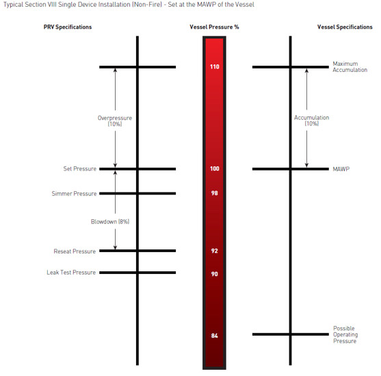
A: Typically, the valve should be nameplate set to open at the MAWP (Maximum Allowable Working Pressure) of the vessel the valve is intended to protect. There is a tolerance to actual set pressure, which means a valve set at 100 psig nameplate may open slightly above or below 100 psig. Consult the current ASME Boiler and Pressure Vessel Code for tolerance classes and special situations when the set pressure may be different than the MAWP.
A: It is normal for spring-operated safety valves to exhibit leakage or simmer/warn, as the system operating pressure approaches the nameplate set pressure, typically in the 80%-90% range of nameplate set pressure. The ASME Boiler and Pressure Vessel Code does not require a specific seat tightness requirement. A certain level of leakage is allowed per manufacturers’ literature and API-527 Seat Tightness Performance Standards, both of which can be found in the Technical Reference Catalog and in the Data Supplement, summarized as follows:
API-527 Standard Seat Tightness Performance: A Functional Test Report (FTR) is automatically provided for valves ordered to API-527. See API 527 for complete details.
A: Maintain a minimum operating gap of 10% between the system operating pressure and the safety valve’s nameplate set pressure. Since direct spring-operated safety valves may “simmer” or “warn” at 90% of the nameplate set pressure, and since the factory standard leak test is performed at 80% of nameplate set pressure, better seat tightness performance can be expected with an operating gap of 20%.
Variance of set pressure is allowed, i.e., a Section VIII air valve with a nameplate of 100 psig set pressure may open from 97 psig to 103 psig, but will be factory set around 102 psig.
Gage issues may lead to incorrect reporting of set pressure. Ensure the gage is within calibration and is accurate for the pressure being measured. Rapid increases in system pressure (more than 2 psig/second, water hammer, reciprocating pumps) can make the valve appear to be opening early because the gage cannot accurately report the pressure to which the valve is exposed.
A: Yes. Section I valves have more stringent setting blowdown requirements and may be used in Section VIII steam applications since they meet all the requirements as specified in Section VIII UG-125(a) “Pressure Relief Devices,” which states pressure relief devices must be “in accordance with the requirements of UG-125 through UG-137.” In addition, UG-125(b) actually specifies that even unfired steam boilers MUST use a Section I pressure relief device.
A: Section VIII UG-136(a)(3) states, “Each pressure relief valve on air, water over 140° F (60° C), or steam service shall have a substantial lifting device which when activated will release the seating force on the disk when the pressure relief valve is subjected to a pressure of at least 75% of the set pressure of the valve.”
The user has a documented procedure and an associated implementation program for the periodic removal of the pressure relief valves for inspection and testing, and repair as necessary.
A: Back pressure reduces set pressure on a one-to-one basis, i.e., a valve set at 100 psig subjected to a backpressure at the outlet of 10 psig will not actuate until system pressure reaches 110 psig. Back pressure drastically reduces capacity; typically backpressure of 10% of set pressure will decrease capacity by 50%. Specific capacity reduction should be determined by the user on a case-by-case basis by flow testing. Back pressure in excess of 10% of set pressure is not recommended.
A: The ASME Boiler and Pressure Vessel Code does not have blowdown requirements for Section VIII (or non-code) valves. Blowdown may vary from less than 2% to more than 50%, depending on many factors including: valve design, dimensional tolerance variation, where the set pressure falls in the set pressure range of a spring, spring rate/force ratio, warn ring/guide settings, etc. Typical blowdown for most valves is 15% to 30%, but cannot be guaranteed. VM
Jim Knox is president, Allied Valve, Inc. (www.alliedvalve.com), a valve repair service company and supplier of Tyco Kunkle and Dresser Consolidated safety valves in the Midwest. Reach him at knoxj@alliedvalveinc.com.
ValvTechnologies and Severn Glocon have reached a partnership agreement that will see collaboration between two of the world’s leading engineering and manufacturing companies specializing in innovative, high-end, severe-service valves.
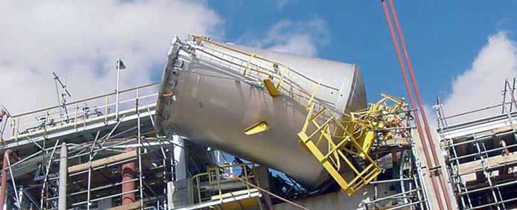
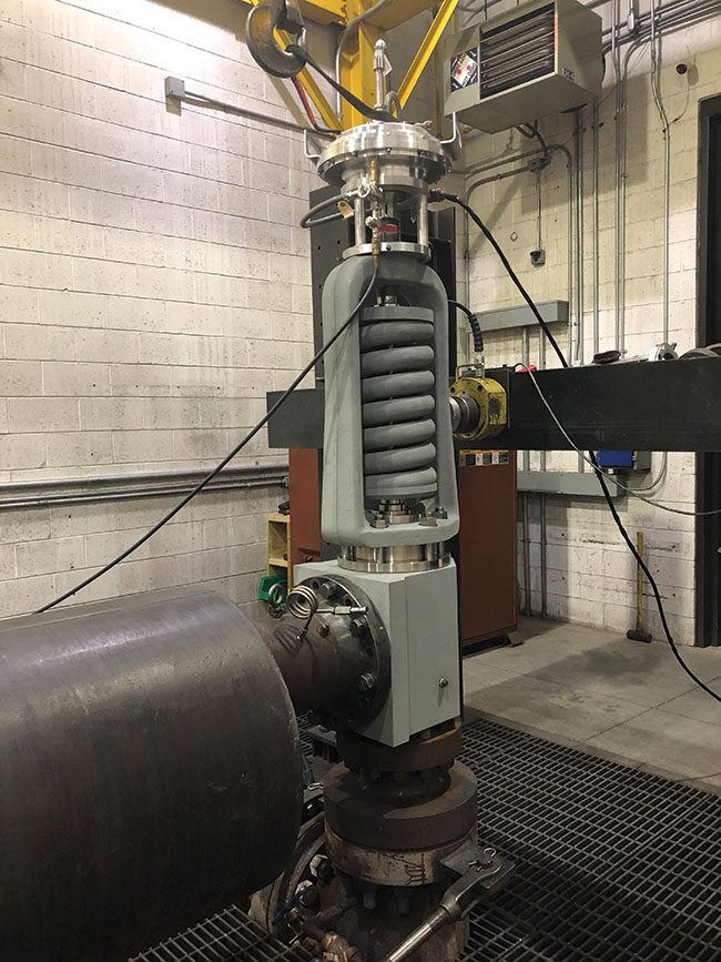
This article outlines the challenges of lifting large valve assemblies weighing several tons and illustrates the industrial rigging equipment and lifting operations typically used for these valves.
The National Board of Boiler & Pressure Vessel Inspectors is an organization comprised of chief inspectors from various states and territories of the US and Province and territories of Canada. The primary mission is to promote public safety.
We sat down to ask a few clarifying questions with our very own Marianne Brodeur, who was the owner of International Valve and Instrument (IVI), before its purchase by Collins in October of 2019. She also sits on the National Board as Chairperson of the subcommittee on Pressure Relief Devices. IVI has held a VR stamp for the last 34 years.

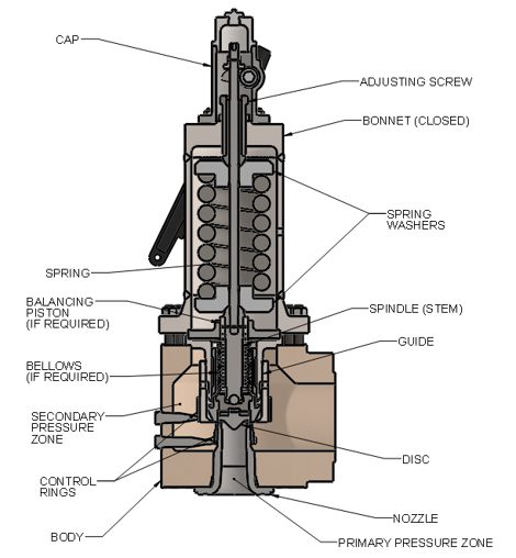
There is a wide range of safety valves available to meet the many different applications and performance criteria demanded by different industries. Furthermore, national standards define many varying types of safety valve.
The ASME standard I and ASME standard VIII for boiler and pressure vessel applications and the ASME/ANSI PTC 25.3 standard for safety valves and relief valves provide the following definition. These standards set performance characteristics as well as defining the different types of safety valves that are used:
ASME I valve - A safety relief valve conforming to the requirements of Section I of the ASME pressure vessel code for boiler applications which will open within 3% overpressure and close within 4%. It will usually feature two blowdown rings, and is identified by a National Board ‘V’ stamp.
ASME VIII valve- A safety relief valve conforming to the requirements of Section VIII of the ASME pressure vessel code for pressure vessel applications which will open within 10% overpressure and close within 7%. Identified by a National Board ‘UV’ stamp.
Full bore safety valve - A safety valve having no protrusions in the bore, and wherein the valve lifts to an extent sufficient for the minimum area at any section, at or below the seat, to become the controlling orifice.
Conventional safety relief valve -The spring housing is vented to the discharge side, hence operational characteristics are directly affected by changes in the backpressure to the valve.
Balanced safety relief valve -A balanced valve incorporates a means of minimising the effect of backpressure on the operational characteristics of the valve.
Pilot operated pressure relief valve -The major relieving device is combined with, and is controlled by, a self-actuated auxiliary pressure relief device.
Power-actuated safety relief valve - A pressure relief valve in which the major pressure relieving device is combined with, and controlled by, a device requiring an external source of energy.
Standard safety valve - A valve which, following opening, reaches the degree of lift necessary for the mass flowrate to be discharged within a pressure rise of not more than 10%. (The valve is characterised by a pop type action and is sometimes known as high lift).
Full lift (Vollhub) safety valve -A safety valve which, after commencement of lift, opens rapidly within a 5% pressure rise up to the full lift as limited by the design. The amount of lift up to the rapid opening (proportional range) shall not be more than 20%.
Direct loaded safety valve -A safety valve in which the opening force underneath the valve disc is opposed by a closing force such as a spring or a weight.
Proportional safety valve - A safety valve which opens more or less steadily in relation to the increase in pressure. Sudden opening within a 10% lift range will not occur without pressure increase. Following opening within a pressure of not more than 10%, these safety valves achieve the lift necessary for the mass flow to be discharged.
Diaphragm safety valve -A direct loaded safety valve wherein linear moving and rotating elements and springs are protected against the effects of the fluid by a diaphragm
Bellows safety valve - A direct loaded safety valve wherein sliding and (partially or fully) rotating elements and springs are protected against the effects of the fluids by a bellows. The bellows may be of such a design that it compensates for influences of backpressure.
Controlled safety valve - Consists of a main valve and a control device. It also includes direct acting safety valves with supplementary loading in which, until the set pressure is reached, an additional force increases the closing force.
Safety valve - A safety valve which automatically, without the assistance of any energy other than that of the fluid concerned, discharges a quantity of the fluid so as to prevent a predetermined safe pressure being exceeded, and which is designed to re-close and prevent further flow of fluid after normal pressure conditions of service have been restored. Note; the valve can be characterised either by pop action (rapid opening) or by opening in proportion (not necessarily linear) to the increase in pressure over the set pressure.
Direct loaded safety valve -A safety valve in which the loading due to the fluid pressure underneath the valve disc is opposed only by a direct mechanical loading device such as a weight, lever and weight, or a spring.
Assisted safety valve -A safety valve which by means of a powered assistance mechanism, may additionally be lifted at a pressure lower than the set pressure and will, even in the event of a failure of the assistance mechanism, comply with all the requirements for safety valves given in the standard.
Supplementary loaded safety valve - A safety valve that has, until the pressure at the inlet to the safety valve reaches the set pressure, an additional force, which increases the sealing force.
Note; this additional force (supplementary load), which may be provided by means of an extraneous power source, is reliably released when the pressure at the inlet of the safety valve reaches the set pressure. The amount of supplementary loading is so arranged that if such supplementary loading is not released, the safety valve will attain its certified discharge capacity at a pressure not greater than 1.1 times the maximum allowable pressure of the equipment to be protected.
Pilot operated safety valve -A safety valve, the operation of which is initiated and controlled by the fluid discharged from a pilot valve, which is itself, a direct loaded safety valve subject to the requirement of the standard.
The common characteristic shared between the definitions of conventional safety valves in the different standards, is that their operational characteristics are affected by any backpressure in the discharge system. It is important to note that the total backpressure is generated from two components; superimposed backpressure and the built-up backpressure:
Subsequently, in a conventional safety valve, only the superimposed backpressure will affect the opening characteristic and set value, but the combined backpressure will alter the blowdown characteristic and re-seat value.
The ASME/ANSI standard makes the further classification that conventional valves have a spring housing that is vented to the discharge side of the valve. If the spring housing is vented to the atmosphere, any superimposed backpressure will still affect the operational characteristics. Thiscan be seen from Figure 9.2.1, which shows schematic diagrams of valves whose spring housings are vented to the discharge side of the valve and to the atmosphere.
By considering the forces acting on the disc (with area AD), it can be seen that the required opening force (equivalent to the product of inlet pressure (PV) and the nozzle area (AN)) is the sum of the spring force (FS) and the force due to the backpressure (PB) acting on the top and bottom of the disc. In the case of a spring housing vented to the discharge side of the valve (an ASME conventional safety relief valve, see Figure 9.2.1 (a)), the required opening force is:
In both cases, if a significant superimposed backpressure exists, its effects on the set pressure need to be considered when designing a safety valve system.
Once the valve starts to open, the effects of built-up backpressure also have to be taken into account. For a conventional safety valve with the spring housing vented to the discharge side of the valve, see Figure 9.2.1 (a), the effect of built-up backpressure can be determined by considering Equation 9.2.1 and by noting that once the valve starts to open, the inlet pressure is the sum of the set pressure, PS, and the overpressure, PO.
Balanced safety valves are those that incorporate a means of eliminating the effects of backpressure. There are two basic designs that can be used to achieve this:
Although there are several variations of the piston valve, they generally consist of a piston type disc whose movement is constrained by a vented guide. The area of the top face of the piston, AP, and the nozzle seat area, AN, are designed to be equal. This means that the effective area of both the top and bottom surfaces of the disc exposed to the backpressure are equal, and therefore any additional forces are balanced. In addition, the spring bonnet is vented such that the top face of the piston is subjected to atmospheric pressure, as shown in Figure 9.2.2.
The bellows arrangement prevents backpressure acting on the upper side of the disc within the area of the bellows. The disc area extending beyond the bellows and the opposing disc area are equal, and so the forces acting on the disc are balanced, and the backpressure has little effect on the valve opening pressure.
Bellows failure is an important concern when using a bellows balanced safety valve, as this may affect the set pressure and capacity of the valve. It is important, therefore, that there is some mechanism for detecting any uncharacteristic fluid flow through the bellows vents. In addition, some bellows balanced safety valves include an auxiliary piston that is used to overcome the effects of backpressure in the case of bellows failure. This type of safety valve is usually only used on critical applications in the oil and petrochemical industries.
Since balanced pressure relief valves are typically more expensive than their unbalanced counterparts, they are commonly only used where high pressure manifolds are unavoidable, or in critical applications where a very precise set pressure or blowdown is required.
This type of safety valve uses the flowing medium itself, through a pilot valve, to apply the closing force on the safety valve disc. The pilot valve is itself a small safety valve.
The diaphragm type is typically only available for low pressure applications and it produces a proportional type action, characteristic of relief valves used in liquid systems. They are therefore of little use in steam systems, consequently, they will not be considered in this text.
The piston type valve consists of a main valve, which uses a piston shaped closing device (or obturator), and an external pilot valve. Figure 9.2.4 shows a diagram of a typical piston type, pilot operated safety valve.
The piston and seating arrangement incorporated in the main valve is designed so that the bottom area of the piston, exposed to the inlet fluid, is less than the area of the top of the piston. As both ends of the piston are exposed to the fluid at the same pressure, this means that under normal system operating conditions, the closing force, resulting from the larger top area, is greater than the inlet force. The resultant downward force therefore holds the piston firmly on its seat.
If the inlet pressure were to rise, the net closing force on the piston also increases, ensuring that a tight shut-off is continually maintained. However, when the inlet pressure reaches the set pressure, the pilot valve will pop open to release the fluid pressure above the piston. With much less fluid pressure acting on the upper surface of the piston, the inlet pressure generates a net upwards force and the piston will leave its seat. This causes the main valve to pop open, allowing the process fluid to be discharged.
When the inlet pressure has been sufficiently reduced, the pilot valve will reclose, preventing the further release of fluid from the top of the piston, thereby re-establishing the net downward force, and causing the piston to reseat.
Pilot operated safety valves offer good overpressure and blowdown performance (a blowdown of 2% is attainable). For this reason, they are used where a narrow margin is required between the set pressure and the system operating pressure. Pilot operated valves are also available in much larger sizes, making them the preferred type of safety valve for larger capacities.
One of the main concerns with pilot operated safety valves is that the small bore, pilot connecting pipes are susceptible to blockage by foreign matter, or due to the collection of condensate in these pipes. This can lead to the failure of the valve, either in the open or closed position, depending on where the blockage occurs.
The terms full lift, high lift and low lift refer to the amount of travel the disc undergoes as it moves from its closed position to the position required to produce the certified discharge capacity, and how this affects the discharge capacity of the valve.
A full lift safety valve is one in which the disc lifts sufficiently, so that the curtain area no longer influences the discharge area. The discharge area, and therefore the capacity of the valve are subsequently determined by the bore area. This occurs when the disc lifts a distance of at least a quarter of the bore diameter. A full lift conventional safety valve is often the best choice for general steam applications.
The disc of a high lift safety valve lifts a distance of at least 1/12th of the bore diameter. This means that the curtain area, and ultimately the position of the disc, determines the discharge area. The discharge capacities of high lift valves tend to be significantly lower than those of full lift valves, and for a given discharge capacity, it is usually possible to select a full lift valve that has a nominal size several times smaller than a corresponding high lift valve, which usually incurs cost advantages.Furthermore, high lift valves tend to be used on compressible fluids where their action is more proportional.
In low lift valves, the disc only lifts a distance of 1/24th of the bore diameter. The discharge area is determined entirely by the position of the disc, and since the disc only lifts a small amount, the capacities tend to be much lower than those of full or high lift valves.
Except when safety valves are discharging, the only parts that are wetted by the process fluid are the inlet tract (nozzle) and the disc. Since safety valves operate infrequently under normal conditions, all other components can be manufactured from standard materials for most applications. There are however several exceptions, in which case, special materials have to be used, these include:
Cast steel -Commonly used on higher pressure valves (up to 40 bar g). Process type valves are usually made from a cast steel body with an austenitic full nozzle type construction.
For all safety valves, it is important that moving parts, particularly the spindle and guides are made from materials that will not easily degrade or corrode. As seats and discs are constantly in contact with the process fluid, they must be able to resist the effects of erosion and corrosion.
The spring is a critical element of the safety valve and must provide reliable performance within the required parameters. Standard safety valves will typically use carbon steel for moderate temperatures. Tungsten steel is used for higher temperature, non-corrosive applications, and stainless steel is used for corrosive or clean steam duty. For sour gas and high temperature applications, often special materials such as monel, hastelloy and ‘inconel’ are used.
Standard safety valves are generally fitted with an easing lever, which enables the valve to be lifted manually in order to ensure that it is operational at pressures in excess of 75% of set pressure. This is usually done as part of routine safety checks, or during maintenance to prevent seizing. The fitting of a lever is usually a requirement of national standards and insurance companies for steam and hot water applications. For example, the ASME Boiler and Pressure Vessel Code states that pressure relief valves must be fitted with a lever if they are to be used on air, water over 60°C, and steam.
A test gag (Figure 9.2.7) may be used to prevent the valve from opening at the set pressure during hydraulic testing when commissioning a system. Once tested, the gag screw is removed and replaced with a short blanking plug before the valve is placed in service.
The amount of fluid depends on the particular design of safety valve. If emission of this fluid into the atmosphere is acceptable, the spring housing may be vented to the atmosphere – an open bonnet. This is usually advantageous when the safety valve is used on high temperature fluids or for boiler applications as, otherwise, high temperatures can relax the spring, altering the set pressure of the valve. However, using an open bonnet exposes the valve spring and internals to environmental conditions, which can lead to damage and corrosion of the spring.
When the fluid must be completely contained by the safety valve (and the discharge system), it is necessary to use a closed bonnet, which is not vented to the atmosphere. This type of spring enclosure is almost universally used for small screwed valves and, it is becoming increasingly common on many valve ranges since, particularly on steam, discharge of the fluid could be hazardous to personnel.
Some safety valves, most commonly those used for water applications, incorporate a flexible diaphragm or bellows to isolate the safety valve spring and upper chamber from the process fluid, (see Figure 9.2.9).
The other advantage of POPRV’s is that whether a snap-acting or modulating pilot is used, the presence of superimposed back pressure does not affect the opening pressure when the valve is in service. This is unlike direct spring safety relief valves, which require expensive and fragile bellows to protect against backpressure.
The modern POPRV can be used confidently in ASME Section VIII applications. POPRV’s provide a leak-free system operation very close to the PRV set pressure. A non-flowing pilot design assures that the POPRV will relief consistently within code tolerances even in “dirty” service applications, thus lower cost of ownership. Since process pressure is used to provide sealing force, a lighter unit weight and smaller size results in a lower cost of installation. POPRV’s provide advanced, reliable, and efficient overpressure protection, utilizing a product technology designed for a wide range of ASME Section VIII applications.

Pressure safety valves are designed to protect process piping and equipment in case of an overpressure event. TEAM Valve Solutions inspects, tests, repairs and re-certifies safety valves at 17 service centers across three continents, and in our fleet of mobile facilities, all of which are audited under the jurisdiction of relevant governing bodies.
Our solutions cover all major safety valve brands and support our customers through an inventory of spare parts and loose-assembled valves. In addition, our facilities are audited and governed by the National Board of Boiler and Pressure Vessel Inspectors. Testing, repair, and assembly are performed under license and guidelines of NBIC, and ASME Section I and VIII.
To ensure accurate in-line setpoint verification, TEAM Valve Solutions utilizes Trevitest, the pioneering system for validating safety valve performance in Conventional and Nuclear Power plants, as well as in other industrial process facilities.

ASME safety valves are used across several applications including low-pressure and high-pressure boilers, process equipment, and air, gas, and vapor equipment. We have multiple products in a range of configurations and material construction that meet ASME Class I, IV, and VIII.

Your pressure relief valves (PRVs) are some of the most important pieces of equipment in your plant. They are what protects your systems from overpressure events that can damage your systems and, in some cases, have catastrophic consequences.
One of the most common questions we get is about relief valve testing frequency. There is no single answer that’s right for every valve or application. It depends on the service conditions, valve condition, and level of performance desired.
Effort should be made to conduct inspections and testing of pressure relieving devices at the time they become due in accordance with the schedule previously established, assuming that the equipment has been in continuous operation, interrupted only by the normal shutdown.
The required testing frequency depends on the service. For example, a valve used in a corrosive or fouling service needs to be tested more often than the same valve used in a noncorrosive, nonfouling service. Other conditions that call for shorter testing intervals include:
It’s also important to look at the valve testing history over time. If the valve consistently passes the test, then it can be tested less often. If the results are inconsistent, then the valve should be tested more often. For new processes, especially those where the service conditions (corrosion, fouling, etc.) can’t be accurately predicted, the initial inspection should be performed “as soon as practical after operations begin to establish a safe and suitable testing interval.”
Our valve technicians are factory-trained and ASME and National Board certified to test PRVs from all valve manufacturers.Contact us to learn how we can help you keep your plant up and running.


 8613371530291