
asme safety valve testing requirements price
The ASME Pressure Relief Device (PRD) Testing Laboratory Accreditation Program accredits manufacturers of pressure relief devices and assemblers of pressure relief valves. It is a hybrid program in that it accredits both the manufacturer and specific personnel within the manufacturing organization (the authorized observer). It is operated in conjunction with The National Board of Boiler and Pressure Vessel Inspectors. Therefore, a manufacturer seeking this accreditation submits an application directly to ASME, but details about the program and review process can be found on The National Board of Boiler and Pressure Vessel Inspector"s website.
Companies that have been accredited through the PRD Accreditation Program are operating in accordance with the applicable rules of the associated ASME BPVC, the ASME PTC-25 standard, "Pressure Relief Devices," as well as one of the standards of construction accepted by The National Board of Boiler and Pressure Vessel Inspectors.
Possibly the most important single safety device on a boiler or pressure vessel, the pressure relief device (PRD) is all that stands between overpressure conditions and catastrophic explosions. This comprehensive review of the design, construction, installation, operation, inspection and maintenance of pressure relieving devices currently in use on boilers and pressure vessels details how to protect pressurized equipment from exceeding the maximum allowable working pressure.
This course is designed for engineers of all levels from early career engineers to experienced engineers. It is an essential resource for mechanical engineers, and design engineers; process engineers, and chemical engineers; reliability engineers, and maintenance engineers; inspectors, and testing engineers; as well as plant supervisors, and managers.
ThisASME Virtual Classroom course is held live with an instructor on our online learning platform. Certificate of completion will be issued to registrants who successfully attend and complete the course.

The National Board’s goal is to maintain the integrity of the National Board marks and symbols (NB,VR, andT/O) and the ASME Certification mark with V ,UV, UD, HV, and NV designators. By doing so, we make it possible for National Board members to rely on the presence of these marks in their efforts to protect the general public.
The National Board offers the Certificate of Authorization and VR Stamp for the repair of pressure relief valves. Requirements are included in the current mandatory edition of the National Board Inspection Code(NBIC), Part 4, and NB-514, Accreditation of VR Repair Organizations.
The National Board offers the Certificate of Authorization for use of the T/O mark which indicates accreditation as a pressure relief valve Testing Organization. The program includes provisions for minor adjustments to restore valve performance. Requirements are based upon the current mandatory edition of the National Board Inspection Code(NBIC), Part 2, Part 4, and NB-528, Accreditation of T/O Test Only Organizations.
Representatives from the National Board are assigned to visit company sites to select production sample valves for testing at National Board- and ASME- accepted labs.
Many processes involve the use of high pressure steam, water or air. Piping systems carrying these fluids must be protected from over-pressures that could cause damage or injury. A pressure relief valve is a device that opens to vent any pressure higher than the relief valve’s operating set point. The water heater in your house, for example, has a pressure relief valve set to open at a pressure that is lower than the burst pressure of the heater tank. That way if pressure inside the tank exceeds the relief valve’s set point pressure, the valve will open and vent the pressure before the tank is damaged – you get a wet floor but you don’t have to replace the heater tank.
Pressure relief valves come in all sizes and pressures and these are critical parts of a high pressure piping system carrying steam in an industrial plants, refineries, power plants, etc. The ASME has established criteria for the size and set point pressures for relief valves operating in industrial systems. Additionally, these valve are tested on a regular basis to insure that they open at the correct pressure and do not impede the flow of fluid as the pressure is vented. The vales are tested at their operating pressures and temperatures, and the opening pressure and pressure drop through the valve as it vents must be measured.
There are testing laboratories that are used to test industrial pressure relief valves by simulating the operating conditions for water, air and steam. One customer of Validyne has a test lab capable of generating up to 10,000 lbs. per hour of steam at 300 psig, air flows to 3500 SCFM at 500 psig and water flow rates of 500 gpm at 300 psig. Pressure relief valves are tested depending on their operating conditions, and the valves are instrumented to verify correct operation at their set point pressure.
The Validyne product used to make relief valve measurements is the DP15 pressure transducers. One transducer is used to measure the pressure upstream of the relief valve, a second DP15 measures the downstream pressure. These transducers are 300 or 500 psi, depending on the test. A third DP15 measures the pressure drop across the relief valve when it is flowing and this transducer is typically 100 In H2O full scale. The DP15s are used because they can be mounted remotely from the control station. A large steam relief valve, for example, is connected to piping with runs of 25 and 30 feet. The DP15 can be mounted at the measurement point and the cable to the demodulator can be up to 50 feet with no compromise in calibration.
The pressure transducers are connected to Validyne CD23 demodulator with digital display. The CD23 features large LED displays that are helpful for the operator to see while opening and closing large control valves during the test. The display can be given directly in PSIG and the CD23 provides an analog output proportional to pressure that can be connected to a LabVIEW computer to record the pressures during the test. Alternatively the pressure sensors can also be connected to the USB2250 DAQ.
The Validyne CD23s and DP15s have given many years of service in this difficult environment and this reliability, plus the ability to interface to a data acquisition system make it a great solution for relief valve testing.
Tired of keeping track of your valve inventory’s annual certification records? We offer complete management of your safety relief valves. With an inventory of repair parts and in stock relief valves of all sizes, we can respond to any customer emergency. We offer annual certification services as well as repair of all major brands, including Kunkle, Conbraco, Consolidated, Dresser, Apollo and more.

As your full-service partner, we offer setting and testing services to verify valve performance and validate conformance with stringent ASME and military specifications. This certification testing provides an extra layer of safety and ensures added confidence and peace of mind.
At our state-of-the-art test facilities in California and Virginia, we can conduct functional testing on all types and sizes of pressure relief valves. Please contact us to discuss your specific testing requirements. Our capabilities include but are not limited to:
Air service relief valves in accordance with ASME Section VIII, MIL-V-22549, MIL-V-20065C and ASTM F1508. Sizes 1/4″ – 8″, Pressures 3 PSIG – 6000 PSIG
Liquid service relief valves in accordance with ASME Section VIII, MIL-V-24332, MIL-V-20065C and ASTM F1508. Sizes 1/4″ – 8″, Pressures 3 PSIG – 1500 PSIG
Steam service relief valves in accordance with ASME Section I and Section VIII, ASTM F 1508 and MIL-V-20065, Revisions C & D. Sizes 1/4″ – 8″, Pressures 3 PSIG – 2000 PSIG
Dante Valve offers valve repair services for its commercial/industrial valves. The following repair guidelines have been implemented as of May 1, 2019:
Valves with a new purchase value of $600 or less are not economically feasible to repair. In this situation, customers will be offered a new valve, rather than a repair.
The valve to be repaired will be evaluated for warranty repair. If found to be a warranty repair, the valve will be repaired at no cost to the customer. If found not to be a warranty repair, the valve will be evaluated for repair or returned to the customer.
Repair evaluations will be billed at our standard hourly rate. If the customer chooses to have Dante Valve complete the repair work, the evaluation charge will be waived.
The National Board of Boiler & Pressure Vessel Inspectors is an organization comprised of chief inspectors from various states and territories of the US and Province and territories of Canada. The primary mission is to promote public safety.
We sat down to ask a few clarifying questions with our very own Marianne Brodeur, who was the owner of International Valve and Instrument (IVI), before its purchase by Collins in October of 2019. She also sits on the National Board as Chairperson of the subcommittee on Pressure Relief Devices. IVI has held a VR stamp for the last 34 years.
The primary role of a safety relief valve is to prevent over-pressure situations in pressurized vessels or systems. If the tank’s relief valve fails, it can lead to an accident that destroys property, life, or landscape.
The National Board of Boiler and Pressure Vessel Inspectors is one of the governing bodies for the testing and/or repair of ASME Safety Relief Valves.
You, as the owner of the valve, can test it, but it must be done in accordance with the National Board Inspection Code and your state’s and/or local regulations.
Based on the National Board Code, which bases their inspection intervals on what type of service the valve is used for, the following intervals are suggested:
Also, keep in mind that this piping should be oriented so that no liquid relieved through this piping can flow back and rest on the ASME safety relief valve’s outlet port.
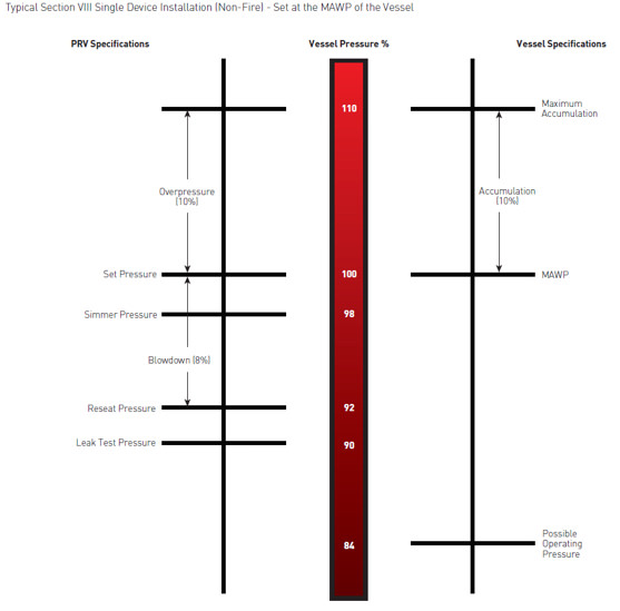
The ASME relief valves are set to fully open at its “set” pressure but will begin to partially open before then – normally at 10% below its set pressure.
If your valve is allowed to do this, trash and/or corrosion can set in over time which could prevent the valve from either closing completely or from fully opening, either of which is not a favorable solution.

Pressure safety valves are designed to protect process piping and equipment in case of an overpressure event. TEAM Valve Solutions inspects, tests, repairs and re-certifies safety valves at 17 service centers across three continents, and in our fleet of mobile facilities, all of which are audited under the jurisdiction of relevant governing bodies.
Our solutions cover all major safety valve brands and support our customers through an inventory of spare parts and loose-assembled valves. In addition, our facilities are audited and governed by the National Board of Boiler and Pressure Vessel Inspectors. Testing, repair, and assembly are performed under license and guidelines of NBIC, and ASME Section I and VIII.
To ensure accurate in-line setpoint verification, TEAM Valve Solutions utilizes Trevitest, the pioneering system for validating safety valve performance in Conventional and Nuclear Power plants, as well as in other industrial process facilities.
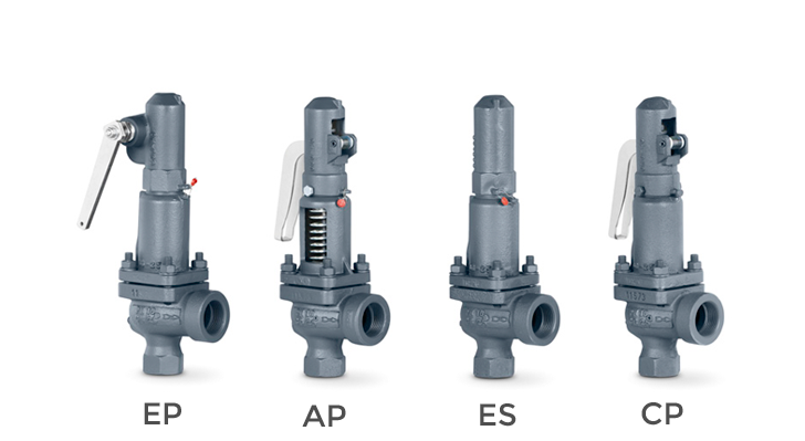
There is a wide range of safety valves available to meet the many different applications and performance criteria demanded by different industries. Furthermore, national standards define many varying types of safety valve.
The ASME standard I and ASME standard VIII for boiler and pressure vessel applications and the ASME/ANSI PTC 25.3 standard for safety valves and relief valves provide the following definition. These standards set performance characteristics as well as defining the different types of safety valves that are used:
ASME I valve - A safety relief valve conforming to the requirements of Section I of the ASME pressure vessel code for boiler applications which will open within 3% overpressure and close within 4%. It will usually feature two blowdown rings, and is identified by a National Board ‘V’ stamp.
ASME VIII valve- A safety relief valve conforming to the requirements of Section VIII of the ASME pressure vessel code for pressure vessel applications which will open within 10% overpressure and close within 7%. Identified by a National Board ‘UV’ stamp.
Full bore safety valve - A safety valve having no protrusions in the bore, and wherein the valve lifts to an extent sufficient for the minimum area at any section, at or below the seat, to become the controlling orifice.
Conventional safety relief valve -The spring housing is vented to the discharge side, hence operational characteristics are directly affected by changes in the backpressure to the valve.
Balanced safety relief valve -A balanced valve incorporates a means of minimising the effect of backpressure on the operational characteristics of the valve.
Pilot operated pressure relief valve -The major relieving device is combined with, and is controlled by, a self-actuated auxiliary pressure relief device.
Power-actuated safety relief valve - A pressure relief valve in which the major pressure relieving device is combined with, and controlled by, a device requiring an external source of energy.
Standard safety valve - A valve which, following opening, reaches the degree of lift necessary for the mass flowrate to be discharged within a pressure rise of not more than 10%. (The valve is characterised by a pop type action and is sometimes known as high lift).
Full lift (Vollhub) safety valve -A safety valve which, after commencement of lift, opens rapidly within a 5% pressure rise up to the full lift as limited by the design. The amount of lift up to the rapid opening (proportional range) shall not be more than 20%.
Direct loaded safety valve -A safety valve in which the opening force underneath the valve disc is opposed by a closing force such as a spring or a weight.
Proportional safety valve - A safety valve which opens more or less steadily in relation to the increase in pressure. Sudden opening within a 10% lift range will not occur without pressure increase. Following opening within a pressure of not more than 10%, these safety valves achieve the lift necessary for the mass flow to be discharged.
Diaphragm safety valve -A direct loaded safety valve wherein linear moving and rotating elements and springs are protected against the effects of the fluid by a diaphragm
Bellows safety valve - A direct loaded safety valve wherein sliding and (partially or fully) rotating elements and springs are protected against the effects of the fluids by a bellows. The bellows may be of such a design that it compensates for influences of backpressure.
Controlled safety valve - Consists of a main valve and a control device. It also includes direct acting safety valves with supplementary loading in which, until the set pressure is reached, an additional force increases the closing force.
Safety valve - A safety valve which automatically, without the assistance of any energy other than that of the fluid concerned, discharges a quantity of the fluid so as to prevent a predetermined safe pressure being exceeded, and which is designed to re-close and prevent further flow of fluid after normal pressure conditions of service have been restored. Note; the valve can be characterised either by pop action (rapid opening) or by opening in proportion (not necessarily linear) to the increase in pressure over the set pressure.
Direct loaded safety valve -A safety valve in which the loading due to the fluid pressure underneath the valve disc is opposed only by a direct mechanical loading device such as a weight, lever and weight, or a spring.
Assisted safety valve -A safety valve which by means of a powered assistance mechanism, may additionally be lifted at a pressure lower than the set pressure and will, even in the event of a failure of the assistance mechanism, comply with all the requirements for safety valves given in the standard.
Supplementary loaded safety valve - A safety valve that has, until the pressure at the inlet to the safety valve reaches the set pressure, an additional force, which increases the sealing force.
Note; this additional force (supplementary load), which may be provided by means of an extraneous power source, is reliably released when the pressure at the inlet of the safety valve reaches the set pressure. The amount of supplementary loading is so arranged that if such supplementary loading is not released, the safety valve will attain its certified discharge capacity at a pressure not greater than 1.1 times the maximum allowable pressure of the equipment to be protected.
Pilot operated safety valve -A safety valve, the operation of which is initiated and controlled by the fluid discharged from a pilot valve, which is itself, a direct loaded safety valve subject to the requirement of the standard.
The common characteristic shared between the definitions of conventional safety valves in the different standards, is that their operational characteristics are affected by any backpressure in the discharge system. It is important to note that the total backpressure is generated from two components; superimposed backpressure and the built-up backpressure:
Subsequently, in a conventional safety valve, only the superimposed backpressure will affect the opening characteristic and set value, but the combined backpressure will alter the blowdown characteristic and re-seat value.
The ASME/ANSI standard makes the further classification that conventional valves have a spring housing that is vented to the discharge side of the valve. If the spring housing is vented to the atmosphere, any superimposed backpressure will still affect the operational characteristics. Thiscan be seen from Figure 9.2.1, which shows schematic diagrams of valves whose spring housings are vented to the discharge side of the valve and to the atmosphere.
By considering the forces acting on the disc (with area AD), it can be seen that the required opening force (equivalent to the product of inlet pressure (PV) and the nozzle area (AN)) is the sum of the spring force (FS) and the force due to the backpressure (PB) acting on the top and bottom of the disc. In the case of a spring housing vented to the discharge side of the valve (an ASME conventional safety relief valve, see Figure 9.2.1 (a)), the required opening force is:
In both cases, if a significant superimposed backpressure exists, its effects on the set pressure need to be considered when designing a safety valve system.
Once the valve starts to open, the effects of built-up backpressure also have to be taken into account. For a conventional safety valve with the spring housing vented to the discharge side of the valve, see Figure 9.2.1 (a), the effect of built-up backpressure can be determined by considering Equation 9.2.1 and by noting that once the valve starts to open, the inlet pressure is the sum of the set pressure, PS, and the overpressure, PO.
Balanced safety valves are those that incorporate a means of eliminating the effects of backpressure. There are two basic designs that can be used to achieve this:
Although there are several variations of the piston valve, they generally consist of a piston type disc whose movement is constrained by a vented guide. The area of the top face of the piston, AP, and the nozzle seat area, AN, are designed to be equal. This means that the effective area of both the top and bottom surfaces of the disc exposed to the backpressure are equal, and therefore any additional forces are balanced. In addition, the spring bonnet is vented such that the top face of the piston is subjected to atmospheric pressure, as shown in Figure 9.2.2.
The bellows arrangement prevents backpressure acting on the upper side of the disc within the area of the bellows. The disc area extending beyond the bellows and the opposing disc area are equal, and so the forces acting on the disc are balanced, and the backpressure has little effect on the valve opening pressure.
Bellows failure is an important concern when using a bellows balanced safety valve, as this may affect the set pressure and capacity of the valve. It is important, therefore, that there is some mechanism for detecting any uncharacteristic fluid flow through the bellows vents. In addition, some bellows balanced safety valves include an auxiliary piston that is used to overcome the effects of backpressure in the case of bellows failure. This type of safety valve is usually only used on critical applications in the oil and petrochemical industries.
Since balanced pressure relief valves are typically more expensive than their unbalanced counterparts, they are commonly only used where high pressure manifolds are unavoidable, or in critical applications where a very precise set pressure or blowdown is required.
This type of safety valve uses the flowing medium itself, through a pilot valve, to apply the closing force on the safety valve disc. The pilot valve is itself a small safety valve.
The diaphragm type is typically only available for low pressure applications and it produces a proportional type action, characteristic of relief valves used in liquid systems. They are therefore of little use in steam systems, consequently, they will not be considered in this text.
The piston type valve consists of a main valve, which uses a piston shaped closing device (or obturator), and an external pilot valve. Figure 9.2.4 shows a diagram of a typical piston type, pilot operated safety valve.
The piston and seating arrangement incorporated in the main valve is designed so that the bottom area of the piston, exposed to the inlet fluid, is less than the area of the top of the piston. As both ends of the piston are exposed to the fluid at the same pressure, this means that under normal system operating conditions, the closing force, resulting from the larger top area, is greater than the inlet force. The resultant downward force therefore holds the piston firmly on its seat.
If the inlet pressure were to rise, the net closing force on the piston also increases, ensuring that a tight shut-off is continually maintained. However, when the inlet pressure reaches the set pressure, the pilot valve will pop open to release the fluid pressure above the piston. With much less fluid pressure acting on the upper surface of the piston, the inlet pressure generates a net upwards force and the piston will leave its seat. This causes the main valve to pop open, allowing the process fluid to be discharged.
When the inlet pressure has been sufficiently reduced, the pilot valve will reclose, preventing the further release of fluid from the top of the piston, thereby re-establishing the net downward force, and causing the piston to reseat.
Pilot operated safety valves offer good overpressure and blowdown performance (a blowdown of 2% is attainable). For this reason, they are used where a narrow margin is required between the set pressure and the system operating pressure. Pilot operated valves are also available in much larger sizes, making them the preferred type of safety valve for larger capacities.
One of the main concerns with pilot operated safety valves is that the small bore, pilot connecting pipes are susceptible to blockage by foreign matter, or due to the collection of condensate in these pipes. This can lead to the failure of the valve, either in the open or closed position, depending on where the blockage occurs.
The terms full lift, high lift and low lift refer to the amount of travel the disc undergoes as it moves from its closed position to the position required to produce the certified discharge capacity, and how this affects the discharge capacity of the valve.
A full lift safety valve is one in which the disc lifts sufficiently, so that the curtain area no longer influences the discharge area. The discharge area, and therefore the capacity of the valve are subsequently determined by the bore area. This occurs when the disc lifts a distance of at least a quarter of the bore diameter. A full lift conventional safety valve is often the best choice for general steam applications.
The disc of a high lift safety valve lifts a distance of at least 1/12th of the bore diameter. This means that the curtain area, and ultimately the position of the disc, determines the discharge area. The discharge capacities of high lift valves tend to be significantly lower than those of full lift valves, and for a given discharge capacity, it is usually possible to select a full lift valve that has a nominal size several times smaller than a corresponding high lift valve, which usually incurs cost advantages.Furthermore, high lift valves tend to be used on compressible fluids where their action is more proportional.
In low lift valves, the disc only lifts a distance of 1/24th of the bore diameter. The discharge area is determined entirely by the position of the disc, and since the disc only lifts a small amount, the capacities tend to be much lower than those of full or high lift valves.
Except when safety valves are discharging, the only parts that are wetted by the process fluid are the inlet tract (nozzle) and the disc. Since safety valves operate infrequently under normal conditions, all other components can be manufactured from standard materials for most applications. There are however several exceptions, in which case, special materials have to be used, these include:
Cast steel -Commonly used on higher pressure valves (up to 40 bar g). Process type valves are usually made from a cast steel body with an austenitic full nozzle type construction.
For all safety valves, it is important that moving parts, particularly the spindle and guides are made from materials that will not easily degrade or corrode. As seats and discs are constantly in contact with the process fluid, they must be able to resist the effects of erosion and corrosion.
The spring is a critical element of the safety valve and must provide reliable performance within the required parameters. Standard safety valves will typically use carbon steel for moderate temperatures. Tungsten steel is used for higher temperature, non-corrosive applications, and stainless steel is used for corrosive or clean steam duty. For sour gas and high temperature applications, often special materials such as monel, hastelloy and ‘inconel’ are used.
Standard safety valves are generally fitted with an easing lever, which enables the valve to be lifted manually in order to ensure that it is operational at pressures in excess of 75% of set pressure. This is usually done as part of routine safety checks, or during maintenance to prevent seizing. The fitting of a lever is usually a requirement of national standards and insurance companies for steam and hot water applications. For example, the ASME Boiler and Pressure Vessel Code states that pressure relief valves must be fitted with a lever if they are to be used on air, water over 60°C, and steam.
A test gag (Figure 9.2.7) may be used to prevent the valve from opening at the set pressure during hydraulic testing when commissioning a system. Once tested, the gag screw is removed and replaced with a short blanking plug before the valve is placed in service.
The amount of fluid depends on the particular design of safety valve. If emission of this fluid into the atmosphere is acceptable, the spring housing may be vented to the atmosphere – an open bonnet. This is usually advantageous when the safety valve is used on high temperature fluids or for boiler applications as, otherwise, high temperatures can relax the spring, altering the set pressure of the valve. However, using an open bonnet exposes the valve spring and internals to environmental conditions, which can lead to damage and corrosion of the spring.
When the fluid must be completely contained by the safety valve (and the discharge system), it is necessary to use a closed bonnet, which is not vented to the atmosphere. This type of spring enclosure is almost universally used for small screwed valves and, it is becoming increasingly common on many valve ranges since, particularly on steam, discharge of the fluid could be hazardous to personnel.
Some safety valves, most commonly those used for water applications, incorporate a flexible diaphragm or bellows to isolate the safety valve spring and upper chamber from the process fluid, (see Figure 9.2.9).

In order to ensure that the maximum allowable accumulation pressure of any system or apparatus protected by a safety valve is never exceeded, careful consideration of the safety valve’s position in the system has to be made. As there is such a wide range of applications, there is no absolute rule as to where the valve should be positioned and therefore, every application needs to be treated separately.
A common steam application for a safety valve is to protect process equipment supplied from a pressure reducing station. Two possible arrangements are shown in Figure 9.3.3.
The safety valve can be fitted within the pressure reducing station itself, that is, before the downstream stop valve, as in Figure 9.3.3 (a), or further downstream, nearer the apparatus as in Figure 9.3.3 (b). Fitting the safety valve before the downstream stop valve has the following advantages:
• The safety valve can be tested in-line by shutting down the downstream stop valve without the chance of downstream apparatus being over pressurised, should the safety valve fail under test.
• When setting the PRV under no-load conditions, the operation of the safety valve can be observed, as this condition is most likely to cause ‘simmer’. If this should occur, the PRV pressure can be adjusted to below the safety valve reseat pressure.
Indeed, a separate safety valve may have to be fitted on the inlet to each downstream piece of apparatus, when the PRV supplies several such pieces of apparatus.
• If supplying one piece of apparatus, which has a MAWP pressure less than the PRV supply pressure, the apparatus must be fitted with a safety valve, preferably close-coupled to its steam inlet connection.
• If a PRV is supplying more than one apparatus and the MAWP of any item is less than the PRV supply pressure, either the PRV station must be fitted with a safety valve set at the lowest possible MAWP of the connected apparatus, or each item of affected apparatus must be fitted with a safety valve.
• The safety valve must be located so that the pressure cannot accumulate in the apparatus viaanother route, for example, from a separate steam line or a bypass line.
It could be argued that every installation deserves special consideration when it comes to safety, but the following applications and situations are a little unusual and worth considering:
• Fire - Any pressure vessel should be protected from overpressure in the event of fire. Although a safety valve mounted for operational protection may also offer protection under fire conditions,such cases require special consideration, which is beyond the scope of this text.
• Exothermic applications - These must be fitted with a safety valve close-coupled to the apparatus steam inlet or the body direct. No alternative applies.
• Safety valves used as warning devices - Sometimes, safety valves are fitted to systems as warning devices. They are not required to relieve fault loads but to warn of pressures increasing above normal working pressures for operational reasons only. In these instances, safety valves are set at the warning pressure and only need to be of minimum size. If there is any danger of systems fitted with such a safety valve exceeding their maximum allowable working pressure, they must be protected by additional safety valves in the usual way.
In order to illustrate the importance of the positioning of a safety valve, consider an automatic pump trap (see Block 14) used to remove condensate from a heating vessel. The automatic pump trap (APT), incorporates a mechanical type pump, which uses the motive force of steam to pump the condensate through the return system. The position of the safety valve will depend on the MAWP of the APT and its required motive inlet pressure.
This arrangement is suitable if the pump-trap motive pressure is less than 1.6 bar g (safety valve set pressure of 2 bar g less 0.3 bar blowdown and a 0.1 bar shut-off margin). Since the MAWP of both the APT and the vessel are greater than the safety valve set pressure, a single safety valve would provide suitable protection for the system.
Here, two separate PRV stations are used each with its own safety valve. If the APT internals failed and steam at 4 bar g passed through the APT and into the vessel, safety valve ‘A’ would relieve this pressure and protect the vessel. Safety valve ‘B’ would not lift as the pressure in the APT is still acceptable and below its set pressure.
It should be noted that safety valve ‘A’ is positioned on the downstream side of the temperature control valve; this is done for both safety and operational reasons:
Operation - There is less chance of safety valve ‘A’ simmering during operation in this position,as the pressure is typically lower after the control valve than before it.
Also, note that if the MAWP of the pump-trap were greater than the pressure upstream of PRV ‘A’, it would be permissible to omit safety valve ‘B’ from the system, but safety valve ‘A’ must be sized to take into account the total fault flow through PRV ‘B’ as well as through PRV ‘A’.
A pharmaceutical factory has twelve jacketed pans on the same production floor, all rated with the same MAWP. Where would the safety valve be positioned?
One solution would be to install a safety valve on the inlet to each pan (Figure 9.3.6). In this instance, each safety valve would have to be sized to pass the entire load, in case the PRV failed open whilst the other eleven pans were shut down.
If additional apparatus with a lower MAWP than the pans (for example, a shell and tube heat exchanger) were to be included in the system, it would be necessary to fit an additional safety valve. This safety valve would be set to an appropriate lower set pressure and sized to pass the fault flow through the temperature control valve (see Figure 9.3.8).
Pressure relief valves (PRVs) are a critical line of defense for pressure vessel protection in the power industry. Generating facilities worldwide depend upon these devices to sense and quickly relieve overpressure conditions to avoid catastrophic damage during process upsets. To ensure these valves will perform as expected, mechanical engineering regulatory bodies mandate the valves be tested on a routine basis.
Some installations make the option of pulling the valve for servicing and testing very difficult. This is particularly true for large size valves, and in the nuclear power industry where valves may be located inside containment areas, making valve access particularly problematic. Fortunately, there is another approved method of testing relief valves for this situation, and this alternative solution is the subject of this article.
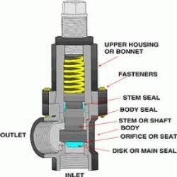
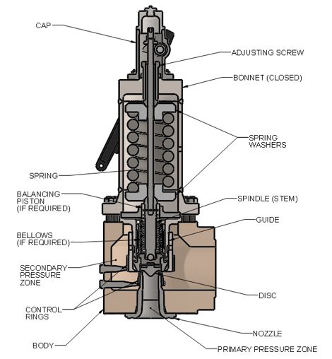
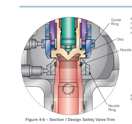
PRVs are relatively, but deceptively, simple devices. They consist of an inlet nozzle attached to the process, which is blocked by a disc held tightly on the nozzle seat (Figure 1). The disc is kept closed by a spring, with adjustments carefully made to dial in the setpoint of the valve.
1. A pressure relief valve (PRV) protects equipment by automatically opening to vent process media when the pressure in the inlet nozzle overcomes the downward force of the spring. Courtesy: Emerson
When the process reaches set pressure, the upward force of the process media offsets the downward force of the spring and the disc lifts off the seat. The process media is relieved through the valve outlet until pressure falls below the setpoint. At this point, the downward force of the spring overcomes the upward force of the process media, and the valve closes.
To ensure the PRV will function when called into action, the American Society of Mechanical Engineers (ASME) mandates relief valves be functionally checked on a routine basis. Typically, a plant will pull smaller valves from their installed position during process outages, and then inspect and test them in a shop environment to confirm they will function as desired and open at the proper pressure setpoint. However, this method of testing is not so easily achieved in certain cases.
Some relief valves are very large and/or located in difficult to reach areas. Others are welded into place and not easily removed from the process. Valves inside nuclear containment areas are particularly troublesome since access to these areas is usually restricted, with strict adherence to extensive protocols required for entry.
To handle these challenging situations, ASME provides alternate means of testing relief valves, as documented in ASME Performance Test Code (PTC) 25 Pressure Relief Devices. These test methods include in-service testing, which allows the plant to functionally test the relief valve without removing it from the process. This in-situ test method can be quite accurate and effective, but only if it is performed correctly with the right equipment.
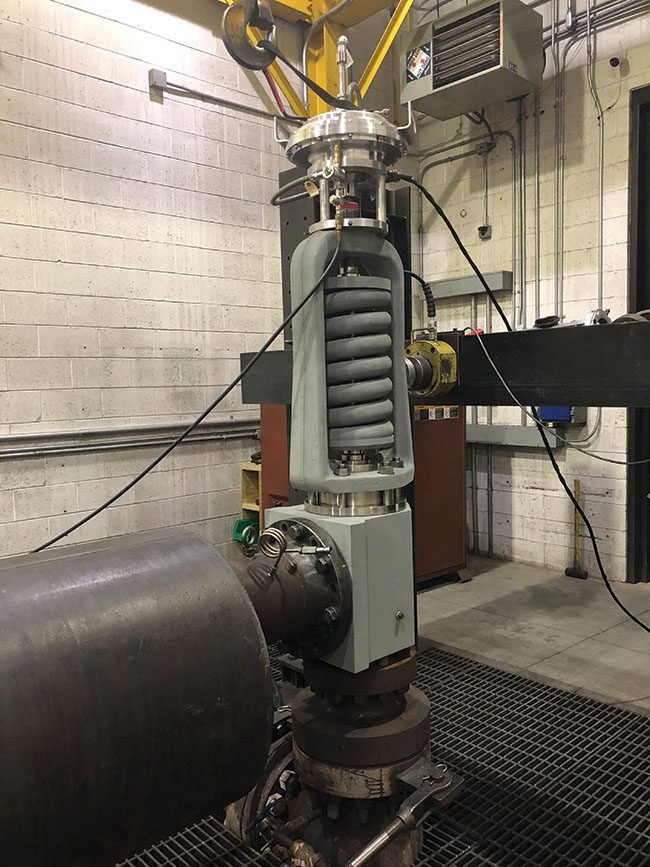
Service and testing of PRVs is typically performed during regular maintenance outages as defined by ASME guidelines. Operating pressures and temperatures are brought down to levels conducive for servicing, and the PRVs are tested by maintenance technicians. For this type of in-service, or in-situ testing, lift assist devices are used in conjunction with these lower system pressures to verify the PRV will operate at the setpoint, within allowable tolerances.
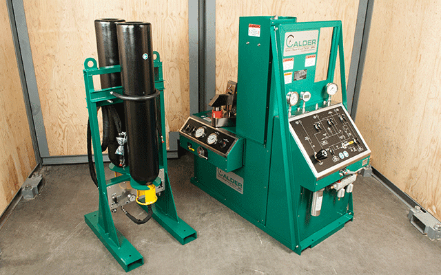
ASME-approved, in-service testing allows the use of lift assist devices attached to the spindle of the valve with adapters, along with other test apparatus to perform set pressure verification testing. The equipment shown in Figure 2 allows a carefully monitored lift force to be applied to the spindle of a PRV until the disc lifts off the seat. The process pressure and the lift force are known, enabling this type of a computer-driven system to determine the setpoint of the PRV, and confirm that it falls within tolerance. This specific type of lift assist equipment is known as a set pressure verification device (SPVD).
2. A portable lift assist, or auxiliary lift device, allows a PRV to be functionally tested without removing the valve from the process. Courtesy: Emerson
There are several other types of lift assist devices available to perform in-service set pressure verification testing, with varying degrees of effectiveness. For most applications, an SPVD is the preferred method of in-service testing.
A linear variable differential transformer (LVDT) is used to detect the earliest sign of valve stem movement, in the range of 0.020 inch, well below the point where the valve will go into full lift. At this time, force and pressure values are obtained, and the test is concluded to avoid wasteful discharge of the process media and minimize seat damage.
Perhaps the most important feature of an SPVD is a fully automated test execution system (Figure 3). This system incorporates an industrially hardened portable laptop computer running automated test protocols, including calibration and diagnostics. The computer can print out certified test results and be connected to up to five relief valves, simplifying and speeding test execution.
Some other types of lift devices are more manual and can only be operated by trained personnel, typically provided by the lift device vendor at considerable expense. However, a fully automated SPVD allows most plant technicians to perform PRV set pressure verification tests as needed. The most useful lift assist devices can be installed on a wide variety of PRVs, rather than just on those from specific manufacturers. Ideally, the lift device should be lightweight and easily adaptable to fit a wide range of relief valves.
Cost and scheduling benefits can be realized from self-test execution, and fully automated PRV set pressure testing also helps ensure consistent and accurate test results, regardless of personnel experience. SPVDs typically provide ASME-certified test results with a proven test accuracy of less than +/–1% error, significantly below the typical ASME test accuracy threshold of +/–3%.
SPVD is often the preferred choice to address a number of challenging PRV test issues. Some valves are very large or not easily removed, so an in-service test is clearly the least costly option (Figure 4). This can especially be true for large relief valves that are welded into the process piping.
4. Emerson’s Crosby SPVD is being used to perform an in-service test on this American Society of Mechanical Engineers (ASME) Section III Class 2 safety valve. Installation and testing of the SPVD does not restrict the PRV from operating should process conditions require the valve to open in service. Courtesy: Emerson
Inside nuclear power plants, many large PRVs are located within containment buildings, where access is extremely limited. For critical PRVs in these areas, SPVD lift assist heads and adapters can be permanently installed on the valves, with test cables routed outside the restricted zone and connected to a computer controller.
Since this type of lift device does not impact valve performance during normal operation or overpressure conditions, the PRV can still operate as necessary. Tests can be remotely performed from outside the containment building by simply plugging the cables into a test system and executing the test. Such an installation allows a plant to safely operate under normal conditions and test their critical PRVs on an as-needed basis, while avoiding any potential radiation exposure.
A well-designed lift assist device is a valuable addition to a plant’s PRV maintenance toolset. Every PRV is required to undergo regular in-service testing requirements as defined by the ASME Operation and Maintenance of Nuclear Power Plants code. The code permits use of lift assist devices to perform set pressure verification testing, which is particularly useful in situations where removing the valve from its installed position is not practical. The right lift assist device allows plant personnel to safely execute scheduled maintenance during outage events, or during operation in other cases, ensuring that critical PRVs are functioning per design with correctly adjusted setpoints.
A fully automated SPVD allows plant personnel to perform these tests consistently and accurately, freeing users to schedule and execute PRV tests, without the need for outside vendor involvement. This saves time and cost, and it removes dependence on a single vendor as a service provider. SPVD also provides a means for nuclear power plants to remotely test their critical relief valves, while avoiding exposure in containment areas.
If faced with a PRV testing challenge, plant personnel should consider lift-assist devices, such as an SPVD, as a potential solution. They meet ASME requirements for set pressure verification testing, and the fully automated operation of SPVD guarantees reliable test results, while providing many other benefits noted in this article.
—June DelGrossois the sales director for North America Nuclear and Navy at Emerson for its flow control products. She has worked for a variety of companies, filling roles such as Valve and Instrument Design Engineer, Product Engineering Manager, and Global Product Technical Leader.


 8613371530291