
natural gas safety valve free sample
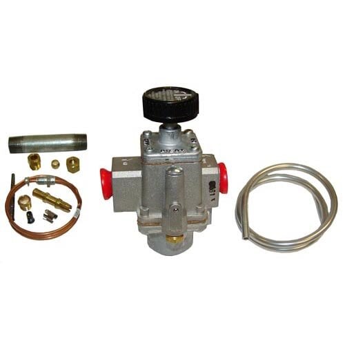
WITT is a manufacturer of Pressure relief valvesor Safety relief valves for technical gases. They are designed to protect against overpressure by discharging pressurized gases and vapors from pipelines, pressure vessels and plant components. Safety relief valves (SRV) are often the last line of defense against explosion – and such an explosion could be fatal. Other common names for safety relief valves are pressure relief valve (PRV), safety valve, pressure safety valve, overpressure valve, relief valve or blow-off valve.
WITT safety valves are very precise. They are individually preset to open at a predetermined pressure within the range 0.07 to 652 Psi. Their small size and orientation-independent installation allow a wide range of connection options. WITT relief valves also stand out due to their high blow-off flow rates of up to 970m³/h. They can be used within a temperature range of -76° F to +518°F and even with very low pressures.
For maximum safety, WITT undertakes 100 % testing of each safety relief valve before it is delivered. In addition, WITT offers individual testing of eachsafety valveby the TÜV, with their certificate as proof of the correct set pressure.
WITTsafety relief valvesare direct-acting, spring-loaded valves. When the preset opening pressure is reached, a spring-loaded element in the valve gives way and opens, and the pressure is relieved. Once the pressures are equalized, the valve closes automatically and can be reactivated any time the pressure rises again. Depending on the application and the nature of the gas, the safety relief valvescan either discharge to atmosphere, or via a connected blow-off line. The opening pressure of the safety valves is preset by WITT at the factory according to the customer’s requirements.
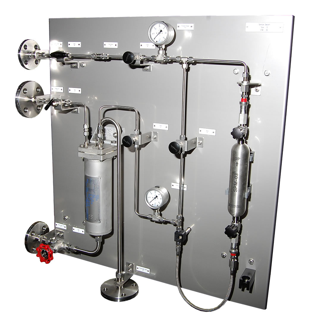
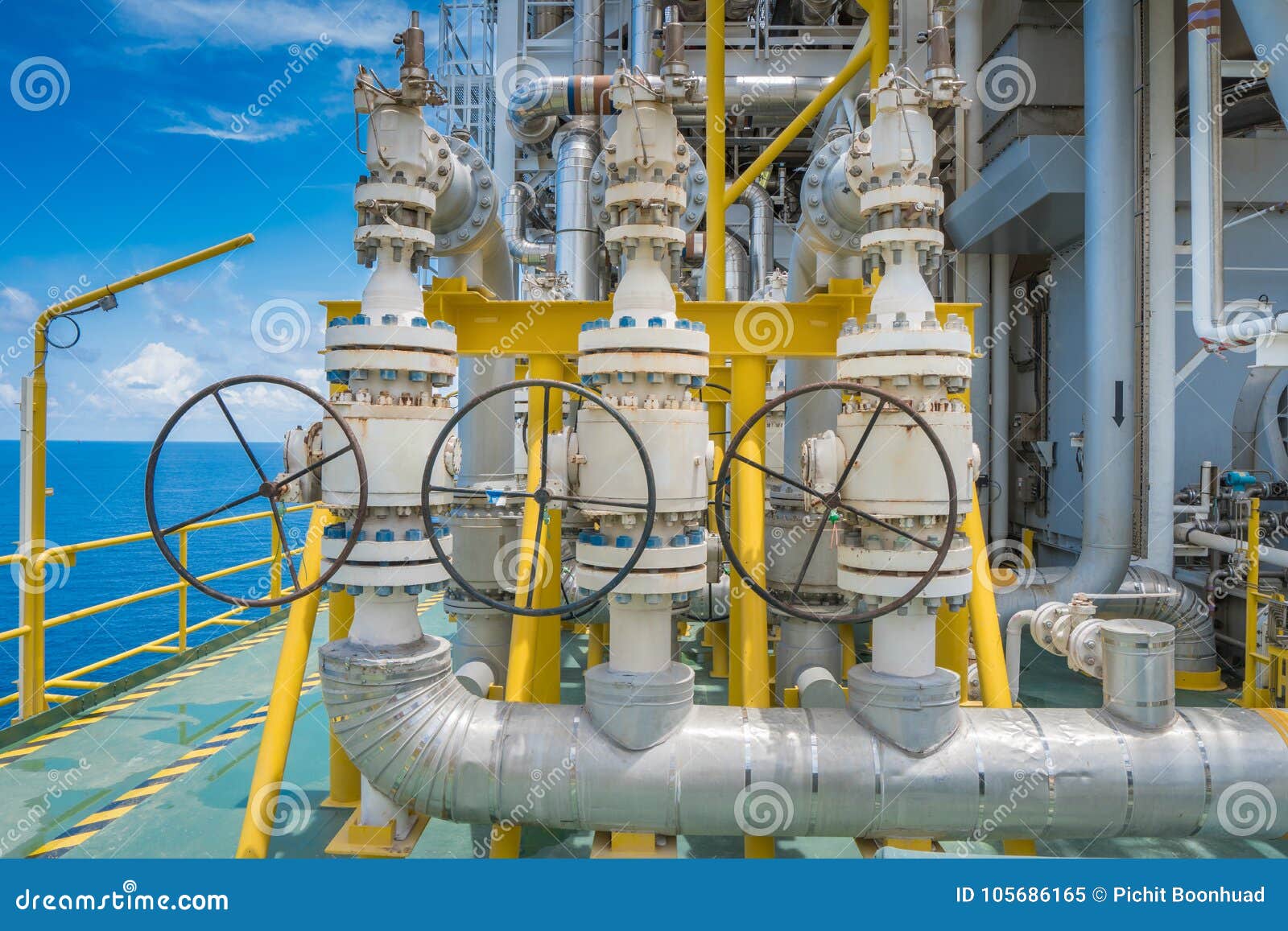
Safety relief valvesare used in numerous industries and industrial applications where, for example, gases pass through pipelines or where special process vessels have to be filled with gas at a certain pressure.
For most industrial applications using technical gases, brass is usually the standard material of construction of thesafety relief valvebody/housing. For the use of pressure relief valves with aggressive and corrosive gases, the housings are made of high-quality stainless steel (1.4541/AISI 321, 1.4404/AISI 316L, 1.4305/AISI 303 or 1.4571/AISI 316Ti). The use of aluminium as a housing material is also possible.
Depending on the type of gas used and individual customer requirements, various sealing materials and elastomers are available to ensure the safety of your systems under even the most difficult conditions.
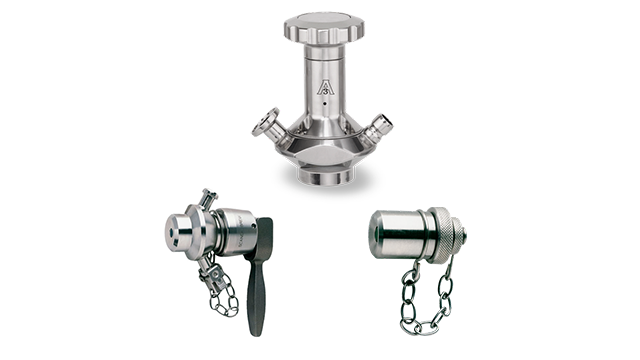
WITT pressure relief valves are available with different connections. In addition to the standard versions with the usual internal or external threads, special versions with KF or CF flanges, VCR or UNF threads can also be ordered. Special adapters for connecting the safety relief valve to a blow-off line are also available.

Besides the P/T value of the sleeve the limitations of the valve bodies also have to be considered. Please refer to the EN 12516-1 resp. ASME B16.34 in order to choose a proper pressure rating (PN/class). The shown values refer to austenitic stainless steel 1.4408 (A351 Gr. CF8M).
Nationwide, our Natural Gas Scratch and sniff cards are used by thousands of public utilities to teach children the risks and safety surrounding natural gas. Below are just a few samples of the cards that we produce. Our standard scratch and sniff cards are printed in full color both sides on a heavy 12 point coated two sides premium card stock with a 1″ Natural Gas scratch & sniff area. We can custom quote any of your needs.
Scratch-and-sniff mercaptan cards teach kids and their families to recognize gas leaks—and how to stay safe if they do notice a leak. One side of the card has a 1″ area of natural gas scent (mercaptan). Once this area is scratched it will release in encapsulated micro cent the mimics the smell of Natural Gas. This area can be repeatedly scratched over a period of time to make sure the child understands and recognizes the smell of natural gas.
To burn, gas must mix with the proper amount of air and be ignited by a flame or a spark. Burning natural gas without enough air produces carbon monoxide, a deadly poison. This is colorless and odorless.
Pure natural gas is also colorless and odorless. A chemical odorant is added that give natural gas a distinctive sulfur-like odor. This is called MERCAPTAN. Our natural gas scratch & sniff mimics this odor to help educate on what to be aware of.
A faint odor of gas may mean that a burner has been left on with no flame, or a pilot light is out. A strong odor means you should leave the home at once and call 911 and your natural gas company ASAP.
Your gas-burning equipment should be inspected regularly by a qualified service person. Check vents, flue pipes, connections, and chimneys periodically for corrosion or blockages.
Contact your local gas utility and request samples of Natural Gas Scratch & Sniff to be mailed to you. By law they are required to have this information available to anyone that requests it.
Use these Scratch & Sniff cards to educate and teach small children what Natural Gas smells like and what they should be aware of if they ever smell it in your home.
Every adult in your family should know where the shut-off valve is at the meter. This valve should be closed only in the event of a gas emergency in your home
Teach small children to stay away from the gas range and all gas burning appliances. Don’t let children swing from or play with pipes leading to water heater or ranges.
Take your family on a guide tour of your homes gas-burning appliances. Make sure they are aware of the consequences in playing or tampering with this equipment.
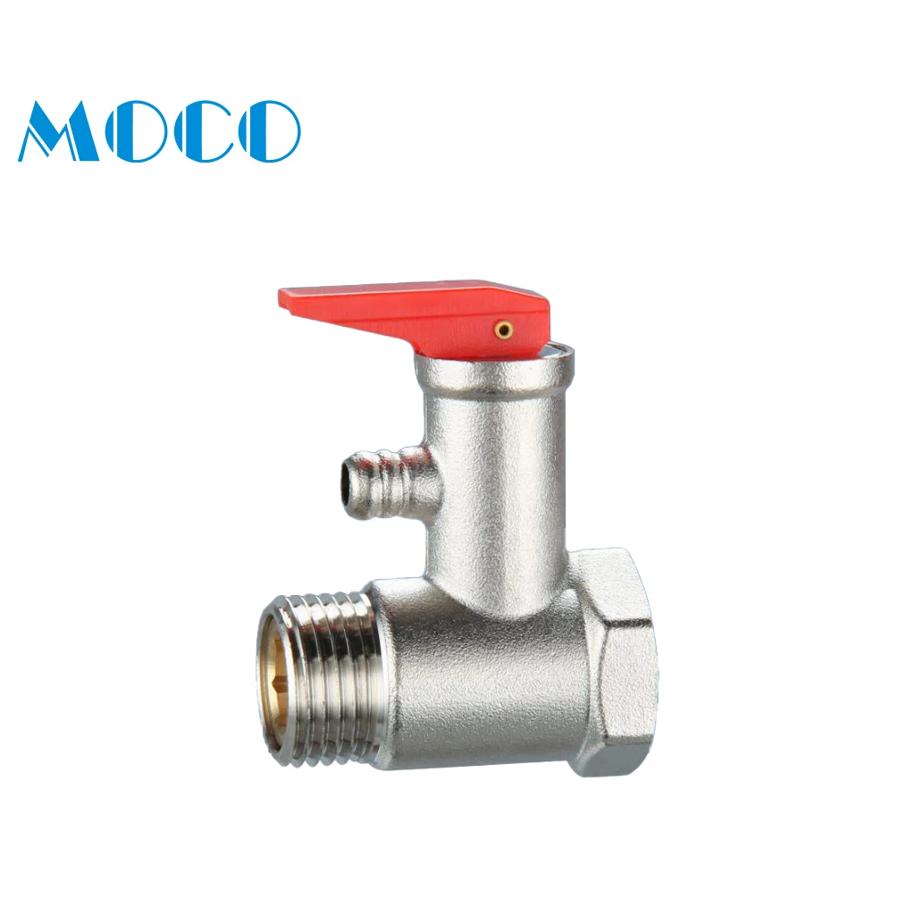
The primary purpose of a safety valve is to protect life, property and the environment. Safety valves are designed to open and release excess pressure from vessels or equipment and then close again.
The function of safety valves differs depending on the load or main type of the valve. The main types of safety valves are spring-loaded, weight-loaded and controlled safety valves.
Regardless of the type or load, safety valves are set to a specific set pressure at which the medium is discharged in a controlled manner, thus preventing overpressure of the equipment. In dependence of several parameters such as the contained medium, the set pressure is individual for each safety application.
A safety valve must always be sized and able to vent any source of steam so that the pressure within the protected apparatus cannot exceed the maximum allowable accumulated pressure (MAAP). This not only means that the valve has to be positioned correctly, but that it is also correctly set. The safety valve must then also be sized correctly, enabling it to pass the required amount of steam at the required pressure under all possible fault conditions.
Once the type of safety valve has been established, along with its set pressure and its position in the system, it is necessary to calculate the required discharge capacity of the valve. Once this is known, the required orifice area and nominal size can be determined using the manufacturer’s specifications.
In order to establish the maximum capacity required, the potential flow through all the relevant branches, upstream of the valve, need to be considered.
In applications where there is more than one possible flow path, the sizing of the safety valve becomes more complicated, as there may be a number of alternative methods of determining its size. Where more than one potential flow path exists, the following alternatives should be considered:
This choice is determined by the risk of two or more devices failing simultaneously. If there is the slightest chance that this may occur, the valve must be sized to allow the combined flows of the failed devices to be discharged. However, where the risk is negligible, cost advantages may dictate that the valve should only be sized on the highest fault flow. The choice of method ultimately lies with the company responsible for insuring the plant.
For example, consider the pressure vessel and automatic pump-trap (APT) system as shown in Figure 9.4.1. The unlikely situation is that both the APT and pressure reducing valve (PRV ‘A’) could fail simultaneously. The discharge capacity of safety valve ‘A’ would either be the fault load of the largest PRV, or alternatively, the combined fault load of both the APT and PRV ‘A’.
This document recommends that where multiple flow paths exist, any relevant safety valve should, at all times, be sized on the possibility that relevant upstream pressure control valves may fail simultaneously.
The supply pressure of this system (Figure 9.4.2) is limited by an upstream safety valve with a set pressure of 11.6 bar g. The fault flow through the PRV can be determined using the steam mass flow equation (Equation 3.21.2):
Once the fault load has been determined, it is usually sufficient to size the safety valve using the manufacturer’s capacity charts. A typical example of a capacity chart is shown in Figure 9.4.3. By knowing the required set pressure and discharge capacity, it is possible to select a suitable nominal size. In this example, the set pressure is 4 bar g and the fault flow is 953 kg/h. A DN32/50 safety valve is required with a capacity of 1 284 kg/h.
Coefficients of discharge are specific to any particular safety valve range and will be approved by the manufacturer. If the valve is independently approved, it is given a ‘certified coefficient of discharge’.
This figure is often derated by further multiplying it by a safety factor 0.9, to give a derated coefficient of discharge. Derated coefficient of discharge is termed Kdr= Kd x 0.9
Critical and sub-critical flow - the flow of gas or vapour through an orifice, such as the flow area of a safety valve, increases as the downstream pressure is decreased. This holds true until the critical pressure is reached, and critical flow is achieved. At this point, any further decrease in the downstream pressure will not result in any further increase in flow.
A relationship (called the critical pressure ratio) exists between the critical pressure and the actual relieving pressure, and, for gases flowing through safety valves, is shown by Equation 9.4.2.
For gases, with similar properties to an ideal gas, ‘k’ is the ratio of specific heat of constant pressure (cp) to constant volume (cv), i.e. cp : cv. ‘k’ is always greater than unity, and typically between 1 and 1.4 (see Table 9.4.8).
Overpressure - Before sizing, the design overpressure of the valve must be established. It is not permitted to calculate the capacity of the valve at a lower overpressure than that at which the coefficient of discharge was established. It is however, permitted to use a higher overpressure (see Table 9.2.1, Module 9.2, for typical overpressure values). For DIN type full lift (Vollhub) valves, the design lift must be achieved at 5% overpressure, but for sizing purposes, an overpressure value of 10% may be used.
For liquid applications, the overpressure is 10% according to AD-Merkblatt A2, DIN 3320, TRD 421 and ASME, but for non-certified ASME valves, it is quite common for a figure of 25% to be used.
Two-phase flow - When sizing safety valves for boiling liquids (e.g. hot water) consideration must be given to vaporisation (flashing) during discharge. It is assumed that the medium is in liquid state when the safety valve is closed and that, when the safety valve opens, part of the liquid vaporises due to the drop in pressure through the safety valve. The resulting flow is referred to as two-phase flow.
The required flow area has to be calculated for the liquid and vapour components of the discharged fluid. The sum of these two areas is then used to select the appropriate orifice size from the chosen valve range. (see Example 9.4.3)
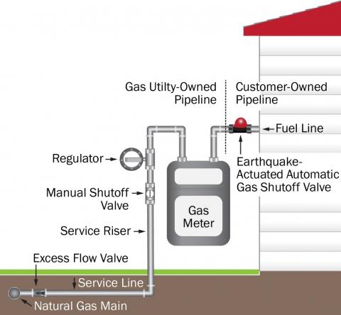
In rare cases, careless excavation work can damage the natural gas lines that serve you. For added protection, installing an Excess Flow Valve (EFV) can shut off the flow of natural gas automatically if the line is damaged or broken. EFVs are not designed to shut off the flow of natural gas for low volume leaks or a faulty appliance.
EFVs are only for services with an operating pressure greater than 10 psig and a total service load of 1,000 SCFH or less. Customer services where an EFV may be installed must be free of contaminants that could interfere with the operation of the device and where the device will not interfere with operation and maintenance activities of customer equipment and appliances. If these conditions are present, an EFV may be installed on your natural gas service line.
EFV installation normally requires the excavation of the natural gas service line at the connection to the main, and a brief service interruption. Following the installation, we will relight your appliances and restore the excavation site. If you would like an EFV installed, we can schedule the work at your convenience.
PECO is committed to delivering natural gas safely and reliably to our more than 523,000 gas customers in Southeastern Pennsylvania. This includes actively monitoring our system during storms and other emergencies. PECO"s preparations for storms include strategically positioning gas mechanics near areas of potential flooding and across the entire service area for a quicker response to reported leaks or damages.
Flooding, poor drainage, and rushing water can erode the ground near buried utilities. Excessive water can potentially cause breaks in natural gas mains, allowing water and dirt to enter the system and disrupt service. Excessive snowfall can impact the functionality of the gas service regulator associated with the customer"s meter. It is the customer"s responsibility to ensure that the regulator can vent properly by clearing snow around the meter set.
For PECO to safely make repairs, crews may need to shut off service to certain customers while isolating the damaged gas main. Therefore, gas mechanics will need to access these customers" natural gas meters.
If a customer is not available to provide access, PECO will work with local authorities to gain access to the property and shut off gas service. This can prolong the restoration of natural gas service for all nearby customers.
The time it takes to restore natural gas service depends on the amount of damage to the natural gas mains. Repair durations depend first on flood water receding and then the time it takes crews to clear all water and debris from the gas mains.
Once all the natural gas meters in the area are disconnected and the gas mains repaired, then PECO can reintroduce natural gas to the mains and restore service to individual customers. This requires a gas mechanic to access customers" gas meters to restore service and relight gas appliances.
Maintain adequate clearance around your natural gas meter. Structures such as porches, decks, paving, building additions or other structures should not obstruct the underground service line leading to the gas meter.
Make sure customer-owned natural gas piping and equipment located after the gas meter is well maintained and regularly inspected for corrosion and leaks by a licensed plumber or HVAC contractor.
Immediately report abnormal natural gas pressure, a loss of service, or water in natural gas pipes, equipment, or appliances to PECO at 1-800-841-4141 or (alternate number) 1-844-841-4151.
Contact PECO to arrange an inspection of its gas equipment if flood waters have shifted your home or caused other stresses to the gas pipes, creating the possibility for a natural gas leak.
During a natural gas outage, please make every effort to be available or to make your gas meter accessible to allow a gas mechanic to disconnect service at your gas meter and eventually to restore service and relight your appliances.
If you suspect a gas leak, do not attempt to find the source or to repair it. Leave the area immediately. Then from a safe place contact PECO at 1-800-841-4141 or (alternate number) 1-844-841-4151 to report the leak.
Keep electrical safety in mindWhen dealing with natural gas issues due to floods and storms, you always should keep electrical safety in mind as well:Do not enter a room with standing water, particularly if it covers electrical outlets or cords or appliances plugged into outlets.
Seismic shut-off valves are a simple, but effective way to ensure you never experience a gas fire after an earthquake. They are designed for earthquakes, accidents and any event of impact. We have installed thousands of automatic gas shut off valves to the manufacture’s specification to ensure safe, trouble free use.
The seismic valves work on a simple, consistent and accurate principle. A sensor moves when the valve is subjected to a 5.4 magnitude or larger earthquake, releasing the valve float which blocks the line and prevents gas going in to the building. The valve is then manually reset once a safety inspection has been done and you’re sure there are no leaks in the building.
Each valve is tested and certified before leaving the factory to meet approval from the State Board of Architect and LA Counties stringent requirements. They are tested to ASCE 25-97, State of California 12-23-1 & ANSI Z21.70-1981 Standards for Seismic Gas Valves.
Some cities and counties in California have regulations that require the installation of automatic gas shut-off devices, which may include excess flow gas shut-off valves and/or seismic gas shut-off valves. Regulations vary, but generally apply to new building construction, or significant alterations or additions to existing buildings.
If a customer installs an automatic gas shut-off valve, it should be one that is certified by the State of California and it should be installed by a licensed plumbing contractor in accordance to the manufacturers instructions.PG&Edoes not install or service seismic actuated or excess flow gas shut-off valves, or recommend specific contractors for customer applications.
Non-emergency shut-offs will occur if the automatic gas shut-off is not installed according to manufacturer’s specifications. For example, the impact of heavy vehicles can trigger a non-emergency shut-off. They operate on movement and shut off the supply of gas to a building, when triggered by a 5.4 magnitude or larger Earthquake.


 8613371530291