
the safety valve reduces pressure at quotation

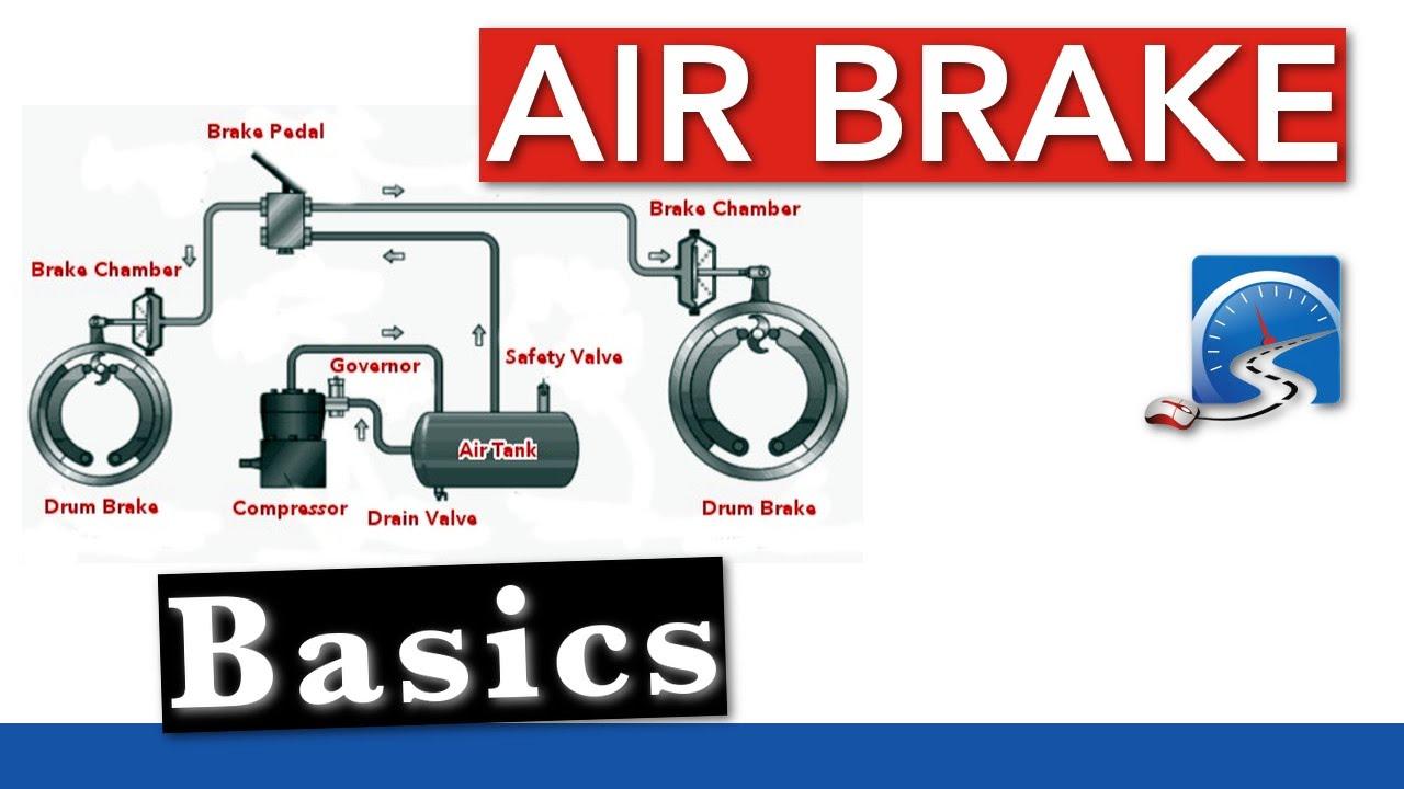
One-Way Check Valve: This device allows air to flow in one direction only. All air tanks on air-braked vehicles must have a check valve located between the air compressor and the first reservoir. The check valve keeps air from going out if the air compressor develops a leak. [California Commercial Driver Handbook]

Park on level ground, chock the wheels, release the parking brake when you have enough air pressure, shut the engine off, and repeatedly press and release the brake pedal.
When performing a final check of your air brake, make sure your vehicle has low air pressure by shutting off the engine, chocking the wheels, and releasing the air pressure by pulling on and off the brakes. Continue doing so until the spring brakes come on automatically, which should be between 20 and 45 psi once you"ve confirmed the low-pressure warning is valid.
This website is using a security service to protect itself from online attacks. The action you just performed triggered the security solution. There are several actions that could trigger this block including submitting a certain word or phrase, a SQL command or malformed data.
Industrial equipment often uses either safety or relief valves to prevent damaging pressure levels from building up. Though they perform similar functions, there are some critical differences between safety and relief valves. Understanding these two valves’ differences is essential for proper pressure system operation. So here we discuss the pressure safety valve vs pressure relief valve.
A pressure relief valve is a device that releases pressure from a system. The relief valve is generally immune to the effects of back pressure and must be periodically stripped down. Pressure relief valves are one the essential parts of a pressure system to prevent system failures. They are set to open at a predetermined pressure level. Each pressure system has a setpoint that is a predetermined limit. The setpoint determines when the valve will open and prevents overpressure.
Pressure relief valves are typically used in gas or liquid systems where there is a need to prevent excessive pressure from building up. When the pressure in the system reaches a certain level, the valve will open and release the pressure. Pressure relief valves are an essential safety feature in many designs and can help to prevent damage to the system or components.
PRVs are generally considered to be safe and reliable devices. However, before installing a PRV in a system, some potential disadvantages should be considered. Here are five pros and cons of pressure relief valves:
Pressure relief valves are anessential safety feature in many systems. They protect against over-pressurization by relieving excess pressure from the system. This can help to prevent severe damage or even explosions.
Pressure relief valves can help to improve the efficiency of a system. The system can operate at lower overall pressure by relieving excess pressure and saving energy.
Pressure relief valves can be used as a safety device in systems that are susceptible to overpressurization. By relieving pressure before it builds up to a dangerous level, they can help to prevent accidents and injuries.
Pressure relief valves can be a potential source of leaks. If not properly maintained, the valve may not seat properly and can allow fluids or gasses to escape.
Pressure relief valves can sometimes cause problems if they do not open or close properly. This can lead to process disruptions and may cause safety issues.
A pressure safety valve is a device used to release pressure from a system that has exceeded its design limit. This safety valve is a fail-safe device. This type of valve is typically used in systems that contain fluids or gasses under high pressure. Pressure safety valves are designed to open and release pressure when the system has exceeded its maximum pressure limit. This helps to prevent the system from rupturing or exploding.
Pressure safety valves are an essential part of many different types of systems and can help keep both people and property safe. If anyone is ever in a situation where they need to release pressure from a system, it is essential to know how to use a pressure safety valve correctly.
A pressure safety valve (PSV) is a type used to relieve a system’s pressure. PSVs are commonly used in chemical and process industries, as well as in some kinds of pressure vessels. There are both advantages and disadvantages to using a PSV. Some of the pros of using a PSV include:
A safety valve is a pressure relief device used to prevent the over-pressurization of a system. On the other hand, a relief valve is a device used to relieve pressure from a system that is already overpressurized.
The function of a pressure relief valve is to protect a system or component from excess pressure. A safety valve, on the other hand, is designed to protect from overpressurization. Both types of valves are used in various industries, but each has unique benefits and drawbacks.
Pressure relief valves are typically used in systems where a small amount of overpressure can cause damage. On the other hand, safety valves are designed for systems where overpressurization could be catastrophic. Both valves have advantages and disadvantages, so choosing the right type of valve for the specific application is essential.
Relief valves are usually set to open at a specific pressure and will close once the pressure has been relieved. Safety valves are similar in that they are also used to protect equipment from excessive pressure. However, safety valves are designed to stay open until they are manually closed. This is because safety valves are typically used in applications where it is not safe to have a closed valve, such as in a gas line.
Two types of valves are commonly used in industrial settings: relief valves and safety valves. Both of these valves serve essential functions, but they operate in different ways.
Relief valves are designed to relieve pressure build-up in a system. They open when the system pressure reaches a certain point, which allows excess pressure to be released. On the other hand, safety valves are designed to prevent accidents by preventing system pressure from getting too high. They open when the system pressure reaches a certain point, which allows excess pressure to be released before an accident can occur.
So, which valve is better? That depends on the situation. A relief valve is the better option to protect the system from pressure build-up. If anyone need to protect the system from accidents, then a safety valve is the better option
The relief valve is made to open when it reaches a specific pressure, commonly described as a “setpoint”. Setpoints shouldn’t be misinterpreted as the pressure set. A setpoint on a relief valve is set to the lowest possible pressure rating, which means it is set to the lowest system pressure before an overpressure situation is observed. The valve will open as the pressure increases to a point higher than the setpoint. The setting point is determined as pounds per square inch (PSIG) and should be within the maximum allowed operating pressure (MAWP) limits. In safety valves, the setpoint is typically placed at about 3 percent over the working pressure level, whereas relief valves are determined at 10 percent.
No, the safety valve and relief valve can not be used interchangeably. Though both valves are seal butterfly valve and used for safety purposes, they serve different functions. A safety valve relieves excess pressure that builds up in a system, while a relief valve regulates the pressure in a system.
Knowing the difference between these two types of valves is essential, as using the wrong valve for the intended purpose can potentially be dangerous. If unsure which type of valve to use, it is always best to consult with a professional.
A few key points help us understand the safety valve vs pressure relief valve. Safety valves are designed to relieve pressure in a system when it gets too high, while relief valves are designed to relieve pressure when it gets too low. Safety valves are usually set to open at a specific pressure, while relief valves are generally open at a particular vacuum. Safety valves are typically intended for one-time use, while relief valves can be used multiple times. Choose the trusted valve manufactureraccording to the specific business needs.

A safety valve is a valve that acts as a fail-safe. An example of safety valve is a pressure relief valve (PRV), which automatically releases a substance from a boiler, pressure vessel, or other system, when the pressure or temperature exceeds preset limits. Pilot-operated relief valves are a specialized type of pressure safety valve. A leak tight, lower cost, single emergency use option would be a rupture disk.
Safety valves were first developed for use on steam boilers during the Industrial Revolution. Early boilers operating without them were prone to explosion unless carefully operated.
Vacuum safety valves (or combined pressure/vacuum safety valves) are used to prevent a tank from collapsing while it is being emptied, or when cold rinse water is used after hot CIP (clean-in-place) or SIP (sterilization-in-place) procedures. When sizing a vacuum safety valve, the calculation method is not defined in any norm, particularly in the hot CIP / cold water scenario, but some manufacturers
The earliest and simplest safety valve was used on a 1679 steam digester and utilized a weight to retain the steam pressure (this design is still commonly used on pressure cookers); however, these were easily tampered with or accidentally released. On the Stockton and Darlington Railway, the safety valve tended to go off when the engine hit a bump in the track. A valve less sensitive to sudden accelerations used a spring to contain the steam pressure, but these (based on a Salter spring balance) could still be screwed down to increase the pressure beyond design limits. This dangerous practice was sometimes used to marginally increase the performance of a steam engine. In 1856, John Ramsbottom invented a tamper-proof spring safety valve that became universal on railways. The Ramsbottom valve consisted of two plug-type valves connected to each other by a spring-laden pivoting arm, with one valve element on either side of the pivot. Any adjustment made to one of valves in an attempt to increase its operating pressure would cause the other valve to be lifted off its seat, regardless of how the adjustment was attempted. The pivot point on the arm was not symmetrically between the valves, so any tightening of the spring would cause one of the valves to lift. Only by removing and disassembling the entire valve assembly could its operating pressure be adjusted, making impromptu "tying down" of the valve by locomotive crews in search of more power impossible. The pivoting arm was commonly extended into a handle shape and fed back into the locomotive cab, allowing crews to "rock" both valves off their seats to confirm they were set and operating correctly.
Safety valves also evolved to protect equipment such as pressure vessels (fired or not) and heat exchangers. The term safety valve should be limited to compressible fluid applications (gas, vapour, or steam).
For liquid-packed vessels, thermal relief valves are generally characterized by the relatively small size of the valve necessary to provide protection from excess pressure caused by thermal expansion. In this case a small valve is adequate because most liquids are nearly incompressible, and so a relatively small amount of fluid discharged through the relief valve will produce a substantial reduction in pressure.
Flow protection is characterized by safety valves that are considerably larger than those mounted for thermal protection. They are generally sized for use in situations where significant quantities of gas or high volumes of liquid must be quickly discharged in order to protect the integrity of the vessel or pipeline. This protection can alternatively be achieved by installing a high integrity pressure protection system (HIPPS).
In the petroleum refining, petrochemical, chemical manufacturing, natural gas processing, power generation, food, drinks, cosmetics and pharmaceuticals industries, the term safety valve is associated with the terms pressure relief valve (PRV), pressure safety valve (PSV) and relief valve.
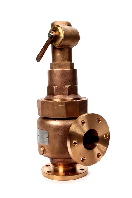
The generic term is Pressure relief valve (PRV) or pressure safety valve (PSV). PRVs and PSVs are not the same thing, despite what many people think; the difference is that PSVs have a manual lever to open the valve in case of emergency.
Relief valve (RV): an automatic system that is actuated by the static pressure in a liquid-filled vessel. It specifically opens proportionally with increasing pressure
Pilot-operated safety relief valve (POSRV): an automatic system that relieves on remote command from a pilot, to which the static pressure (from equipment to protect) is connected
Low pressure safety valve (LPSV): an automatic system that relieves static pressure on a gas. Used when the difference between the vessel pressure and the ambient atmospheric pressure is small.
Vacuum pressure safety valve (VPSV): an automatic system that relieves static pressure on a gas. Used when the pressure difference between the vessel pressure and the ambient pressure is small, negative and near to atmospheric pressure.
Low and vacuum pressure safety valve (LVPSV): an automatic system that relieves static pressure on a gas. Used when the pressure difference is small, negative or positive and near to atmospheric pressure.
In most countries, industries are legally required to protect pressure vessels and other equipment by using relief valves. Also, in most countries, equipment design codes such as those provided by the ASME, API and other organizations like ISO (ISO 4126) must be complied with. These codes include design standards for relief valves and schedules for periodic inspection and testing after valves have been removed by the company engineer.
Today, the food, drinks, cosmetics, pharmaceuticals and fine chemicals industries call for hygienic safety valves, fully drainable and Cleanable-In-Place. Most are made of stainless steel; the hygienic norms are mainly 3A in the USA and EHEDG in Europe.
The first safety valve was invented by Denis Papin for his steam digester, an early pressure cooker rather than an engine.steelyard" lever a smaller weight was required, also the pressure could easily be regulated by sliding the same weight back and forth along the lever arm. Papin retained the same design for his 1707 steam pump.Greenwich in 1803, one of Trevithick"s high-pressure stationary engines exploded when the boy trained to operate the engine left it to catch eels in the river, without first releasing the safety valve from its working load.
Although the lever safety valve was convenient, it was too sensitive to the motion of a steam locomotive. Early steam locomotives therefore used a simpler arrangement of weights stacked directly upon the valve. This required a smaller valve area, so as to keep the weight manageable, which sometimes proved inadequate to vent the pressure of an unattended boiler, leading to explosions. An even greater hazard was the ease with which such a valve could be tied down, so as to increase the pressure and thus power of the engine, at further risk of explosion.
Although deadweight safety valves had a short lifetime on steam locomotives, they remained in use on stationary boilers for as long as steam power remained.
Weighted valves were sensitive to bouncing from the rough riding of early locomotives. One solution was to use a lightweight spring rather than a weight. This was the invention of Timothy Hackworth on his leaf springs.
These direct-acting spring valves could be adjusted by tightening the nuts retaining the spring. To avoid tampering, they were often shrouded in tall brass casings which also vented the steam away from the locomotive crew.
The Salter coil spring spring balance for weighing, was first made in Britain by around 1770.spring steels to make a powerful but compact spring in one piece. Once again by using the lever mechanism, such a spring balance could be applied to the considerable force of a boiler safety valve.
The spring balance valve also acted as a pressure gauge. This was useful as previous pressure gauges were unwieldy mercury manometers and the Bourdon gauge had yet to be invented.
Paired valves were often adjusted to slightly different pressures too, a small valve as a control measure and the lockable valve made larger and permanently set to a higher pressure, as a safeguard.Sinclair for the Eastern Counties Railway in 1859, had the valve spring with pressure scale behind the dome, facing the cab, and the locked valve ahead of the dome, out of reach of interference.
In 1855, John Ramsbottom, later locomotive superintendent of the LNWR, described a new form of safety valve intended to improve reliability and especially to be tamper-resistant. A pair of plug valves were used, held down by a common spring-loaded lever between them with a single central spring. This lever was characteristically extended rearwards, often reaching into the cab on early locomotives. Rather than discouraging the use of the spring lever by the fireman, Ramsbottom"s valve encouraged this. Rocking the lever freed up the valves alternately and checked that neither was sticking in its seat.
A drawback to the Ramsbottom type was its complexity. Poor maintenance or mis-assembly of the linkage between the spring and the valves could lead to a valve that no longer opened correctly under pressure. The valves could be held against their seats and fail to open or, even worse, to allow the valve to open but insufficiently to vent steam at an adequate rate and so not being an obvious and noticeable fault.Rhymney Railway, even though the boiler was almost new, at only eight months old.
Naylor valves were introduced around 1866. A bellcrank arrangement reduced the strain (percentage extension) of the spring, thus maintaining a more constant force.L&Y & NER.
All of the preceding safety valve designs opened gradually and had a tendency to leak a "feather" of steam as they approached "blowing-off", even though this was below the pressure. When they opened they also did so partially at first and didn"t vent steam quickly until the boiler was well over pressure.
The quick-opening "pop" valve was a solution to this. Their construction was simple: the existing circular plug valve was changed to an inverted "top hat" shape, with an enlarged upper diameter. They fitted into a stepped seat of two matching diameters. When closed, the steam pressure acted only on the crown of the top hat, and was balanced by the spring force. Once the valve opened a little, steam could pass the lower seat and began to act on the larger brim. This greater area overwhelmed the spring force and the valve flew completely open with a "pop". Escaping steam on this larger diameter also held the valve open until pressure had dropped below that at which it originally opened, providing hysteresis.
These valves coincided with a change in firing behaviour. Rather than demonstrating their virility by always showing a feather at the valve, firemen now tried to avoid noisy blowing off, especially around stations or under the large roof of a major station. This was mostly at the behest of stationmasters, but firemen also realised that any blowing off through a pop valve wasted several pounds of boiler pressure; estimated at 20 psi lost and 16 lbs or more of shovelled coal.
Pop valves derived from Adams"s patent design of 1873, with an extended lip. R. L. Ross"s valves were patented in 1902 and 1904. They were more popular in America at first, but widespread from the 1920s on.
Although showy polished brass covers over safety valves had been a feature of steam locomotives since Stephenson"s day, the only railway to maintain this tradition into the era of pop valves was the GWR, with their distinctive tapered brass safety valve bonnets and copper-capped chimneys.
Developments in high-pressure water-tube boilers for marine use placed more demands on safety valves. Valves of greater capacity were required, to vent safely the high steam-generating capacity of these large boilers.Naylor valve) became more critical.distilled feedwater and also a scouring of the valve seats, leading to wear.
High-lift safety valves are direct-loaded spring types, although the spring does not bear directly on the valve, but on a guide-rod valve stem. The valve is beneath the base of the stem, the spring rests on a flange some height above this. The increased space between the valve itself and the spring seat allows the valve to lift higher, further clear of the seat. This gives a steam flow through the valve equivalent to a valve one and a half or twice as large (depending on detail design).
The Cockburn Improved High Lift design has similar features to the Ross pop type. The exhaust steam is partially trapped on its way out and acts on the base of the spring seat, increasing the lift force on the valve and holding the valve further open.
To optimise the flow through a given diameter of valve, the full-bore design is used. This has a servo action, where steam through a narrow control passage is allowed through if it passes a small control valve. This steam is then not exhausted, but is passed to a piston that is used to open the main valve.
There are safety valves known as PSV"s and can be connected to pressure gauges (usually with a 1/2" BSP fitting). These allow a resistance of pressure to be applied to limit the pressure forced on the gauge tube, resulting in prevention of over pressurisation. the matter that has been injected into the gauge, if over pressurised, will be diverted through a pipe in the safety valve, and shall be driven away from the gauge.
There is a wide range of safety valves having many different applications and performance criteria in different areas. In addition, national standards are set for many kinds of safety valves.
Safety valves are required on water heaters, where they prevent disaster in certain configurations in the event that a thermostat should fail. Such a valve is sometimes referred to as a "T&P valve" (Temperature and Pressure valve). There are still occasional, spectacular failures of older water heaters that lack this equipment. Houses can be leveled by the force of the blast.
Pressure cookers are cooking pots with a pressure-proof lid. Cooking at pressure allows the temperature to rise above the normal boiling point of water (100 degrees Celsius at sea level), which speeds up the cooking and makes it more thorough.
Pressure cookers usually have two safety valves to prevent explosions. On older designs, one is a nozzle upon which a weight sits. The other is a sealed rubber grommet which is ejected in a controlled explosion if the first valve gets blocked. On newer generation pressure cookers, if the steam vent gets blocked, a safety spring will eject excess pressure and if that fails, the gasket will expand and release excess pressure downwards between the lid and the pan. Also, newer generation pressure cookers have a safety interlock which locks the lid when internal pressure exceeds atmospheric pressure, to prevent accidents from a sudden release of very hot steam, food and liquid, which would happen if the lid were to be removed when the pan is still slightly pressurised inside (however, the lid will be very hard or impossible to open when the pot is still pressurised).
These figures are based on two measurements, a drop from 225 psi to 205 psi for an LNER Class V2 in 1952 and a smaller drop of 10 psi estimated in 1953 as 16 lbs of coal.
"Trial of HMS Rattler and Alecto". April 1845. The very lowest pressure exhibited "when the screw was out of the water" (as the opponents of the principle term it) was 34 lb, ranging up to 60 lb., on Salter"s balance.

In the process industry, both terms refer to safety devices, which generally come in the form of valves, cylinders, and other cylinders that protect people, property, and the environment. Safety valves and relief valves are integral components of process safety. However, they are used for almost identical purposes. Their main difference lies in their operating mechanisms.
In the event of an overpressure, a safety valve or pressure relief valve (PRV) protects pressure-sensitive equipment. It is recommended to strip down relief valves regularly and prevent serious damage due to backpressure. Pressure relief valves are a crucial part of any pressurized system. In order to prevent system failures, you can set the pressure to open at predetermined levels. A setpoint, also known as a predetermined design limit, is set for all pressure systems. When the setpoint is exceeded, an overpressure valve opens.
There are various types of safety valves used in several types of industries, including power plants, petrochemical plants, boilers, oil and gas, pharmaceuticals, and more. Using safety valves helps to prevent accidents and injuries that can harm people, property, and processes. Pressure builds up in vessels and systems automatically when the device is activated above a preset level. Safety valves must be configured so that their prescribed pressure is exceeded in order for them to function (i.e., relieve pressure). Ideally, excess pressure should be released either to the atmosphere or back into the pneumatic system to prevent damage to the vessel. In addition, excess pressure should be released to keep pressure within a certain range. As soon as a slight increase in pressure above the desired limit has lifted the safety valve, it opens.
Valve relief removes excessive pressure from a system by limiting its pressure level to a safe level. Often referred to as pressure relief valves (PRVs) or safety relief valves, these valves provide relief from pressure. The purpose of a relief valve is, for example, to adjust the pressure within a vessel or a system so that a specific level is maintained. The goal of a relief valve, unlike a safety valve, is not to prevent damage to the vessel; rather, it is to control the pressure limit of a system dynamically depending on the requirements. Conversely, safety valves have a maximum allowable pressure set at a certain level, which allows escaping liquid or gas whenever the pressure exceeds it, eliminating damage to the system. It is imperative that safety valves are installed in a control system to prevent the development of pressure fluctuations that can cause property damage, life loss, and environmental pollution.
The hydraulic system relies on a pressure relief system in order to regulate the running pressure. By allowing excess pressure to escape from the pressurized zone, pressure relief valves and safety valves prevent overpressure when the pressure in the system reaches a predefined limit. By venting excess pressure through a relief port, or returning it through a return line, a pneumatic system can enable the excess pressure to escape into the atmosphere. Pump-driven pressure generators and control media that cannot be vented into the atmosphere are typical examples of this type of application.
Excess pressure may be relieved from the system using relief valves and safety valves. The valve opening increases proportionally as the vessel pressure increases with the relief valve. Gradually opening the valve rather than abruptly releases only a prescribed amount of fluid. As pressure is reduced, the release proceeds at this rate until the pressure drops. By contrast, an emergency safety valve operates automatically when a predetermined pressure is reached in the system, preventing a catastrophic system failure. When the system is under excessive stress, the safety valve regulates the pressure within the system and prevents overpressure.
Defining a “setpoint” is the process of defining a pressure level which triggers the device to vent excess pressure. Setpoint is different from pressure. Overpressure is prevented by setting these devices lower than the highest pressure the system can handle before overpressure occurs. Setting the device below this pressure prevents overpressure. The valve opens when pressure rises above the setpoint. A setpoint also known as the maximum allowable working pressure (MAWP) cannot be exceeded when deciding the pressure in pounds per square inch (PSIG). The adjustment points for safety valves are generally 3 percent above working pressures, while adjustment points for relief valves are 10% above working pressures.
Pressure in an auxiliary passage can be controlled by a safety valve as well as a relief valve by releasing excess pressure. Safety valves of this type are pressure-sensitive and reliable. Safety valves can be categorized according to their capacity and setpoint, although both terms often refer to safety valves. Self-opening devices open automatically when maximum allowable pressure has been reached rather than being manually activated to prevent over-pressurizing. Contrary to relief valves, safety valves are typically used for venting steam or vapor into the atmosphere. Relief valves regulate fluid flow and compressed air pressure and gases, whereas safety valves typically regulate steam and vapor venting. Put simply, relief valves are used for more gradual pressure control requiring accurate, dynamic systems, whereas safety valves are used for one set to prevent damage to a system.
For pressure control applications that require dynamic setpoints and therefore varying pressure limits, our Electronic Relief Valve is the appropriate solution. This device accepts a control voltage to dynamically set the relief pressure setpoint. Traditional relief valves are set manually, so that a technician must adjust the relief valve and have a pressure gauge to find the accurate setpoint. The Kelly Pneumatic Electronic Relief Valve allows an electronic control system to quickly and safely command a dynamic maximum pressure based on feedback from current system specifications. The Kelly Electronic Relief Valve also has an optional feedback signal representing the current pressure in the system. This allows the control system to dynamically respond to changing conditions.
Finding a quality driving school in can be a difficult and time consuming task. driving-schools.com comprehensive database of driving schools helps you pick one that’s right for you.
Materials that flow through valves during important operating conditions can be affected by hazards, meaning that the valves could be failing. Noise emission, valve and pipe component erosion, and mechanical vibration in the valves and the connected pipelines are all signs that the valves are failing.
According to an article by Empowering Valves, “Safety valves were first put in use approximately 100 years ago on steam boilers during the industrial era. They were created with the sole purpose of keeping heating and other related pieces of equipment from exploding. Today, the sole purpose of these valves is to safeguard an operation from a number of hazards by opening or closing during certain conditions.”
Safety valves are also used in gas or vapor operations. They’re typically created specifically to deal with the chemical that is being used, such as ammonia, butane, and natural gas. It’s important that this safety relief valve can relieve the capacity of the connected compressor at operating pressure.
Empowering Valves describes vacuum valves as being used “to prevent tank collapse when it is being emptied, in addition to clean in place or sterilization in place procedures. They are also installed on top of storage tanks to control fugitive emission losses that can result from handling flammable and hazardous petroleum products that produce vapor.”
Other types of vacuum valves that are known as breather valves, conservation vents, and safety vents are designed to protect process systems, tanks and equipment.
If you’re in need of quality valves, CPV Manufacturing has just what you’re looking for. Today, CPV is known around the world for the O-SEAL System of high pressure valves and fittings, the Mark VIII system or tube size valves and fittings, FloMaster air operated shutoff valves, and the new G-Series stainless steel shutoff, needle & check valves.The valves available at CPV Manufacturing are high-quality and reliable so you can count on them to last. Contact us directly to learn more.

The main purpose of a safety valve is to prevent the pressure in a system to exceed the certification pressure. Above certification pressure, no one can guaranty the systems safety - and especially for a steam system with very hot gas with huge amount of latent heat, the consequences can be dramatically.
The size of the safety valve depends primarily on the maximum boiler output and the operation pressure of the system. The safety valve shall as minimum have the evacuation capacity of all the vapor the boiler can produce running at full power at working (or certification) pressure.
The table below can be used to select a typical safety valve based on boiler output. Before final design, always consult the manufactures documentation.
Note! The table above is based on low pressure steam of 100 kN/m2 (1 bar)or 15 psiin imperial units. Latent heat of saturated steam is 2201 kJ/kg (945 Btu/lb). 1 N/m2 = 1 Pa = 1.4504 x 10⁻⁴ lb/in2 (psi) = 10-5 bar For higher pressure, steam is compressed and require less volume - required size of the valve reduced
Safety is of the utmost importance when dealing with pressure relief valves. The valve is designed to limit system pressure, and it is critical that they remain in working order to prevent an explosion. Explosions have caused far too much damage in companies over the years, and though pressurized tanks and vessels are equipped with pressure relief vales to enhance safety, they can fail and result in disaster.
That’s also why knowing the correct way to test the valves is important. Ongoing maintenance and periodic testing of pressurized tanks and vessels and their pressure relief valves keeps them in working order and keep employees and their work environments safe. Pressure relief valves must be in good condition in order to automatically lower tank and vessel pressure; working valves open slowly when the pressure gets high enough to exceed the pressure threshold and then closes slowly until the unit reaches the low, safe threshold. To ensure the pressure relief valve is in good working condition, employees must follow best practices for testing them including:
If you consider testing pressure relief valves a maintenance task, you’ll be more likely to carry out regular testing and ensure the safety of your organization and the longevity of your
It’s important to note, however, that the American Society of Mechanical Engineers (ASME) and National Board Inspection Code (NBIC), as well as state and local jurisdictions, may set requirements for testing frequency. Companies are responsible for checking with these organizations to become familiar with the testing requirements. Consider the following NBIC recommendations on the frequency for testing relief valves:
High-pressure steam boilers greater than 15 psi and less than 400 psi – perform manual check every six months and pressure test annually to verify nameplate set pressure
High-pressure steam boilers 400 psi and greater – pressure test to verify nameplate set pressure every three years or as determined by operating experience as verified by testing history
High-temperature hot water boilers (greater than 160 psi and/or 250 degrees Fahrenheit) – pressure test annually to verify nameplate set pressure. For safety reasons, removal and testing on a test bench is recommended
When testing the pressure relief valve, raise and lower the test lever several times. The lever will come away from the brass stem and allow hot water to come out of the end of the drainpipe. The water should flow through the pipe, and then you should turn down the pressure to stop the leak, replace the lever, and then increase the pressure.
One of the most common problems you can address with regular testing is the buildup of mineral salt, rust, and corrosion. When buildup occurs, the valve will become non-operational; the result can be an explosion. Regular testing helps you discover these issues sooner so you can combat them and keep your boiler and valve functioning properly. If no water flows through the pipe, or if there is a trickle instead of a rush of water, look for debris that is preventing the valve from seating properly. You may be able to operate the test lever a few times to correct the issue. You will need to replace the valve if this test fails.
When testing relief valves, keep in mind that they have two basic functions. First, they will pop off when the pressure exceeds its safety threshold. The valve will pop off and open to exhaust the excess pressure until the tank’s pressure decreases to reach the set minimum pressure. After this blowdown process occurs, the valve should reset and automatically close. One important testing safety measure is to use a pressure indicator with a full-scale range higher than the pop-off pressure.
Thus, you need to be aware of the pop-off pressure point of whatever tank or vessel you test. You always should remain within the pressure limits of the test stand and ensure the test stand is assembled properly and proof pressure tested. Then, take steps to ensure the escaping pressure from the valve is directed away from the operator and that everyone involved in the test uses safety shields and wears safety eye protection.
After discharge – Because pressure relief valves are designed to open automatically to relieve pressure in your system and then close, they may be able to open and close multiple times during normal operation and testing. However, when a valve opens, debris may get into the valve seat and prevent the valve from closing properly. After discharge, check the valve for leakage. If the leakage exceeds the original settings, you need to repair the valve.
According to local jurisdictional requirements – Regulations are in place for various locations and industries that stipulate how long valves may operate before needing to be repair or replaced. State inspectors may require valves to be disassembled, inspected, repaired, and tested every five years, for instance. If you have smaller valves and applications, you can test the valve by lifting the test lever. However, you should do this approximately once a year. It’s important to note that ASME UG136A Section 3 requires valves to have a minimum of 75% operating pressure versus the set pressure of the valve for hand lifting to be performed for these types of tests.
Depending on their service and application– The service and application of a valve affect its lifespan. Valves used for clean service like steam typically last at least 20 years if they are not operated too close to the set point and are part of a preventive maintenance program. Conversely, valves used for services such as acid service, those that are operated too close to the set point, and those exposed to dirt or debris need to be replaced more often.
Pressure relief valves serve a critical role in protecting organizations and employees from explosions. Knowing how and when to test and repair or replace them is essential.
This website is using a security service to protect itself from online attacks. The action you just performed triggered the security solution. There are several actions that could trigger this block including submitting a certain word or phrase, a SQL command or malformed data.

Hydraulic and pneumatic systems must regulate air or liquid pressure according to a constant pressure threshold. If the pressure exceeds the set level, it can damage equipment and create a safety hazard for workers. Pressure relief valves regulate pressure levels to prevent these dangers.
Pressure relief valves (PRVs), or back pressure regulators, reduce system pressure when it exceeds a maximum threshold. PRVs can also reduce pressure peaks that could damage equipment elsewhere in the facility. The main components of a pressure relief valve are:
When the pressure in the hose or pipe exceeds the pressure limit, will push against the diaphragm, compress the spring and open the valve. The valve opens and closes to maintain the specified pressure level. When the pressure dips below the accepted threshold, the valve closes. With adjustable PRVs, operators can adjust the spring mechanism to collapse under a higher or lower amount of pressure.
Enhances safety: PRVs were invented as a result of boilers exploding when they were not properly monitored. Thus, they are an easy and effective way to keep your system safe.
Increases efficiency: Relief valves automatically reclose when the pressure lowers to the set level, preventing excess loss of expensive gases from the system.
Protects system components: By regulating the pressure in your system, PRVs protect downstream components from damage that might otherwise result from pressure pulses.
Materials: Most valves are made of plastic, brass, aluminum, or stainless steel. Weigh each material’s compatibility, advantages, and disadvantages relative to your system’s needs.
Operating temperature: Make sure the valve you choose can handle the expected operating temperature of your application, as the temperature can affect flow capacity and the responsiveness of the spring mechanism.
Air Logic designs and manufactures industrial pneumatic and vacuum control equipment, including preset and adjustable relief valves for medical and other applications. Our adjustable relief valves can be equipped with straight or barbed fittings. Single barbed models work best with exhaust ports that do not need a barb.
We also offer preset options, which we produce by presetting an adjustable valve at the desired pressure level. We test the valve for effectiveness before shipping it to you. Our ISO 9001:2015 certification ensures high-quality, reliable products with every delivery.

Pressure valves regulatethe flow of gas through a pipeline by opening or closing in response to changes in the pressure of the gas, air, water, or steam flowing through the pipe. Pressure valves are commonly used on natural gas systems, propane systems, and other types of gas systems.
A pressure valve regulates the flow of gas through pipelines by opening or closing in accordance with changes in the pressure of gas flowing through the pipe, thereby maintaining a constant pressure within the pipeline.
Pressure valves work by using a spring-loaded diaphragm or electrical actuator to open or close the valve in the pipeline. As the pressure inside the pipeline rises, the diaphragm moves away from the valve seat, allowing more gas to pass through. Conversely, as the pressure falls, the diaphragms move toward the valve seat, restricting the flow of gas.
Testing a pressure valve should be done before installing it into a system. If there are leaks in the pipe, the valve will not work properly. To test a pressure valve, use a leak detector to check for leaks in the pipe. Then, turn off the main supply line and connect a gauge to the valve. Turn the valve on slowly until the pressure reaches the desired level. Once the pressure has reached the desired level, turn the valve off and wait for the pressure to drop back down to normal levels.
Pressure valve control is used in many applications, but they’re mainly found in all pneumatic and hydraulic systems. Pressure valve control has a wide range of functions that can be used to maintain a set pressure level in a part of a control loop or to keep system pressures below a desired limit.
There are many different types of pressure valve control in the industry, such as pressure relief valves, pressure reducing valves, pressure safety valves, counterbalance valves, unloading valves, and sequencing valves. Most of these pressure valves are typically closed valves, but pressure reducing valves are commonly open valves. It’s important for most of these valves to have restrictions so that the required pressure control can be achieved.
The flow must be consistent at all times in certain applications. Injuries or deaths can be caused by variations in the flow of gases. That’s why pressure control valves are so important in the processing loop.
Pressure relief valves are used to keep the pneumatic and hydraulic systems under the desired pressure value. Based on the different installation positions, pressure relief valves have different functions as below. The downstream pressure should be reduced to a constant level whenever it goes over a threshold.
A pressure relief valve is usually made of three parts: a ball/diaphragm, a spring-loaded mechanism, and a valve nozzle. A spring-loaded mechanism is placed in the valve’s housing, which is used to close the orifice. The pressure relief valve’s spring-loaded mechanism can be adjusted to change the pressure on the spring mechanism. If you want to increase the set pressure limit, just simply increase the pressure on the valve spring-load mechanism directly. If you want to decrease the set pressure limit, only decrease the pressure on the spring-load mechanism directly. A relief valve set-pressure can be specified by the manufacturer if there is no adjustability. When the set pressure is reached, the pressure overcomes the spring pressure and pushes the ball or diaphragm back opening the orifice and releasing the excess pressure. Depending on the media, it is either released into the atmosphere or discharged into it. It is possible to return to a tank or pumping circuit with compressed air.
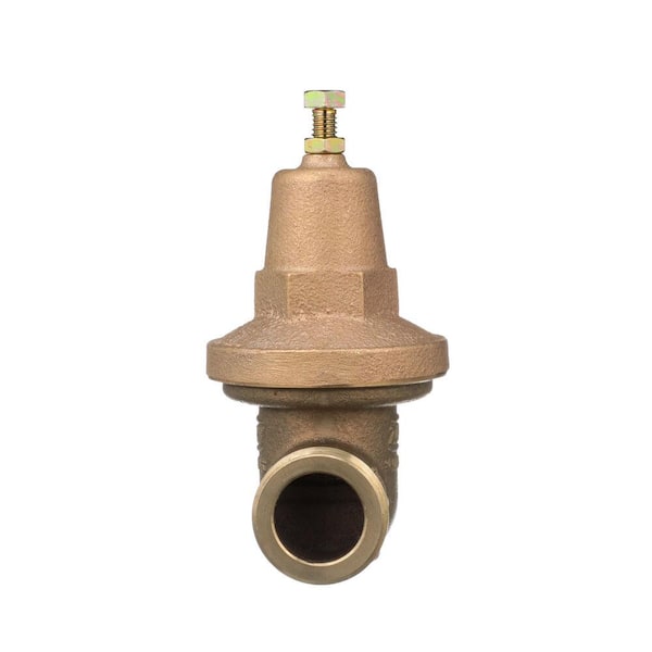
There are two types of PRVs used in industry, one is the direct-acting pressure reducing valves, and the other type is pilot operated pressure reducing valves. The pressure reducing valves use globe type or angle type valve bodies. Most of the time, the main type of valve used in water systems is the direct acting valve, which consists of a globe-type body with a spring-loaded, heat-resistant diaphragm connected to the outlet of the valve that acts upon a spring. This spring holds a pre-set tension on the PRVs seat that’s installed with a pressure equalizing mechanism for precise water pressure control.
Pressure reducing valves are widely used in water conditions, such as in buildings, industrial plants, water treatment plants, homes, and so on. It will automatically reduce the water pressure from the main supply, in case to lower the water pressure to the destination and more sensible pressure for equipment.
Sequence valves are widely used in hydraulic systems, and are a type of pressure valve. Sequence valves are similar to pressure relief valves, but are used to control a set of pressure-related operating sequences. The main function of a sequence valve is to divert the flow in a predetermined sequence, and its construction is very similar to a pressure relief valve, which is a pressure actuated valve, usually a closed valve.
The sequence valve works on the principle that the valve plug will be moved when the main system pressure exceeds the spring setting. As a result, the outlet of the sequence valve will remain closed until the upstream pressure rises to a predetermined value, and then the valve will open, allowing air to transfer from the inlet to the outlet. Sequence valves are primarily used to force two actuators to operate in sequence. One nice feature of the sequence valve is that the valve has a separate drain connection to the spring chamber, under normal operating conditions, high pressures may occur at the output port. When the pressure rises above its limit, the pressure sequence valve will allow flow to occur in another part of the system. The pressure sequence valve is installed in a pneumatic control and its switching operation requires a specific pressure.
Counterbalance valves are used to handle loads that are over-limited and to safely suspend loads, these valves commonly work with hydraulic cylinders. This type of valve can also be used with hydraulic motors and is then commonly referred to as a brake valve. Both counterbalance valves and pilot-operated check valves can be used to lock the fluid in the cylinder to prevent drift. However, pilot-operated check valves cannot control over-running loads. A counterbalance valve should be used when uncontrolled motion may occur with an overrunning load.
The pressure safety valve is one of the most critical automatic safety devices in a pressure system, and in many cases is the last line of defense for safety. The important function of a pressure safety valve is overpressure protection, so ensure that the pressure safety valve can operate properly in any situation. Pressure safety valves are mainly used in pressurized vessels or equipment to protect the environment, property safety, and life safety in the event of an overpressure event. A pressure safety valve opens and releases excess pressure in a vessel or equipment, and closes again when normal conditions are restored and prevents the further release of fluid.
Pressure relief valves (PRV) are designed to help protect compressed air systems from over pressurisation for the safety of personnel and equipment. Norgren offer standard inline compressed air pressure relief valves as well as pop type pressure relief valves.
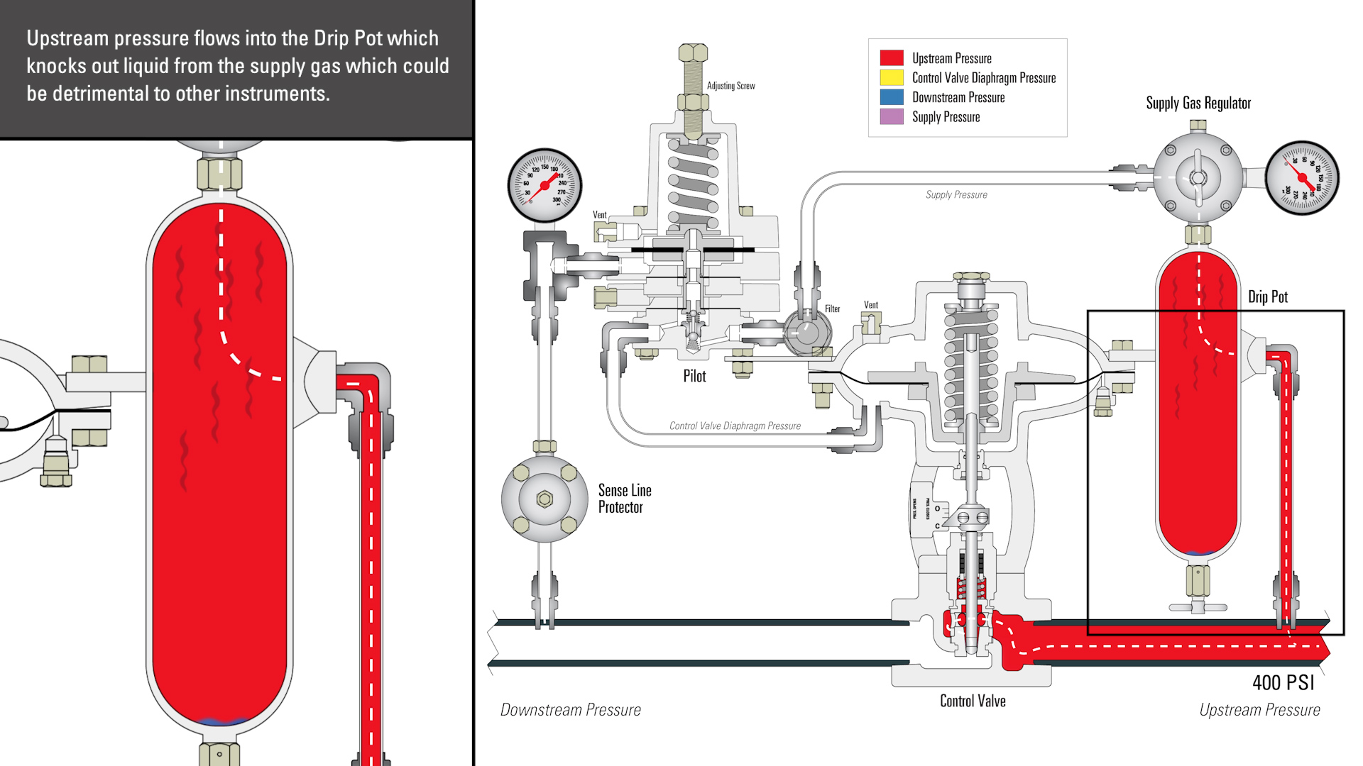
Many industrial plants produce high-pressure steam for process work.In many of these plants, there is excess steam capacity available that can be utilized for other purposes, such as space heating, water heating, etc.Process steam is often generated at a higher pressure than can be used for the other purposes.Whatever the needs for lower pressure steam, a pressure reducing station will be required.
A pressure reducing station is more than just a reducing valve fed off a steam main.A properly designed and installed pressure reducing station takes into consideration velocity, good piping practices, and safety.
After selecting the correct pressure-reducing valve (see Info-Tec 28), the next step in designing the complete reducing station is to pipe size for velocity.The pressure difference created by the reducing valve creates higher steam velocity across the seat of the reducing valve.Sonic velocity will occur.The pipes going into or out of the reducing valve cannot tolerate this.Erosion of materials and excessive noise will be generated.It is good practice to limit steam velocity to between 4000 and 6000 feet per minute to prevent erosion and noise.Properly sized pipes also allow the downstream pressure sensing line to function.Excessive steam velocity passing the sensing line connection will cause inaccurate variable pressures to be sensed as the load varies.Downstream pressure cannot be maintained.
There is a formula to find steam velocity in pipes.Velocity = 2.4 x flow in lbs/hr x sp. vol. in cu. ft./lb at the flowing pressure over the internal area of the pipe in sq. inches.
A pressure-reducing valve has been sized for reducing 100-psig-inlet pressure to 25-psig.Capacity is 1000 lbs/hr. Find the upstream and downstream pipe sizes for reasonable quiet steam velocity.
For upstream pipe size, enter the chart at “A,” 1000 lbs/hr.Go horizontally to where the 1000 lbs/hr line intersects 100 psig, point “B.”From point “B” go vertically to intersect with the first pipe size line inside the shaded area, the 4000 to 6000 FPM area.This is point “C,” 1-1/2” schedule 40-iron pipe.If point “C” is extended horizontally to the right side velocity scale, you see that the actual velocity is about 4800 ft./min., point “D.”
For downstream piping, enter the chart once again at “A.”Go horizontally to the downstream pressure of 25 psig, point “E.”Go vertically from “C” to intersect with the first pipe size line in the shaded area, point “F,” 2-1/2” schedule 40-iron pipe.Actual velocity shown at “G” is about 5500 FPM.
The upstream piping to the pressure regulator should be 1-1/2”, the downstream piping out of the regulator should be 2-1/2.”(If schedule 80 iron pipe is going to be used, note the multiplying factor in the chart.)
Upstream piping size for schedule 40 pipe.Enter chart at 6000 lbs/hr and intersect at 100-lb line.Vertically to first pipe size line in shaded area, 4” pipe.
Downstream Pipe:Enter chart at 6000 lbs/hr.Go to the 10-psig line and vertically intersect it at the 8” pipe.The lengths of these up and downstream pipes are also important.Upstream pipe should be a minimum of six pipe diameters long.Downstream pipe a minimum of 10 pipe diameters long.Using example 2, these pipes should be at least two feet long for upstream, and 80 inches long for downstream.These are minimum lengths and sizes.You can always go longer and larger (cost could become a factor).
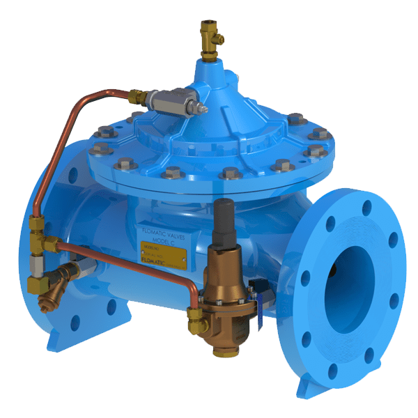
Figure 2is a schematic diagram of a typical pressure reducing station.Study Figure 2.Note the use of eccentric couplings.These prevent formation of water pockets where condensate could collect.A Y pipe strainer is installed laying on its side for the same reason, or it would have to be drained with a trap.Manual ball valves are used as shut-offs to facilitate repair or replacement of failed parts.An optional bypass is used when some steam flow must be maintained at all times, even during repairs.The bypass line size is usually about half the line size of the pressure regulator, since it will only be opened on an emergency basis, for hopefully a relatively short time.
Safety is addressed by using a downstream relief valve with a pressure setting of either 5 lbs over the usual downstream pressure, or 5 lbs under the downstream equipment’s lowest pressure rated item.The relief valve is needed to protect the equipment should the pressure regulator fail.Its capacity rating should, at least, match or exceed the maximum flow rate.Note that if the bypass is ever fully opened, close to full upstream pressure will be applied downstream of the regulator.Codes prevent the installation of a shut-off valve between a relief valve and the system it is protecting, so careful adjustment of the manual bypass valve needs to be observed when using the bypass to prevent the relief valve from opening.
Caution:The system should be constantly attended whenever the bypass is opened.Never remove the relief valve and plug the opening!Expensive damage to equipment could result, not to mention a very unsafe and dangerous condition.
A separator is shown as part of the reducing station to insure “dry” steam enters the pressure regulator.“Wet” steam is very detrimental to a pressure regulator.A separator needs to be drained by a trap system.Unfortunately, separators are expensive and are almost never purchased as part of the reducing station.The steam supply line may (should) be dripped before entering the pressure reducing station.When designing and quoting the reducing station, the separator is best quoted as an option.
Gauges are selected according to the pressures being dealt with.The gauges should be mounted on siphon tube assemblies with valves to facilitate quick and easy replacement.
To keep costs down, the strainer and ball valves are the same pipe size as the pressure regulator and should be as close coupled as possible to the regulator.Use close or short nipples.No unions are shown in Figure 2, but should be used as needed.
The regulator’s sensing line should be pitched down slightly so any condensate will drain out of it.It must be at least four feet long and connect into the larger downstream pipe near the outlet end of the pipe.If copper tube is used for the sensing line, care must be taken not to kink the tube, let is sag, or form any trap in its length.
Figure 4shows such an installation.Chances are the control valve will be the same line size as the pressure regulator.It should be installed downstream of the enlarged downstream piping using eccentrics as shown.The ball valve can be moved downstream of the control valve.If a bypass is used, connect it downstream of the ball valve. As you can see, a steam pressure regulator reducing station is not just a pressure regulator cut into a steam line.The station needs to be carefully designed and properly installed.The entire station should pitch down slightly in the direction of flow.Done correctly, the station will give many years of quiet, satisfactory, performance.

Before you begin pressure-relief system design, watch out for these common mistakes in identifying overpressure scenarios, performing sizing calculations, and installing the system in the field.
Errors in the design and installation of pressure-relieving devices (PRDs) and their respective pressure-relief systems (PRSs) create risk. For example, incomplete documentation is confusing, creates nuisance rework, and can put a facility at risk of citation. Improper equipment selection and installation can also present real safety hazards.
Inexperienced as well as experienced engineers are bound to make or discover mistakes at some point in their careers. If an error is made in PRS design, we must learn from that mistake and communicate that knowledge. This article will help you recognize common rationale, sizing, and installation pitfalls, and eliminate unnecessary risk at the earliest opportunity.
▲Figure 1. It is easier to control cost, process safety, and other factors at the beginning of the design process than during the end stages of a project.
The saying, “The most effective and efficient mitigation or elimination of risk is achieved at the earliest juncture and at the most fundamental level,”can be applied to practically any discipline and any situation, including process safety and pressure-relief system design. In any project, there is the least amount of risk (e.g.,financial, safety, etc.) and the greatest amount of control over change at the onset; the opposite becomes true at the end of a project (Figure 1).
To detect and eliminate design and installation deficiencies, you must understand the physical components within the PRS, as well as the system’s implementation. In other words, understand the big picture. This article first describes the potential pitfalls found at the early stages of the big picture, where we have the most influence over the outcome of a design. It then covers pitfalls found in the later stages of design and post-installation.
Despite notions to the contrary, organizations do not ask engineers to design PRSs to pass the time; the work is purposeful and important to the safe operation of facilities. Just as using a dull knife to cut meat increases risk, asking an unintelligent engineer to design a PRS escalates risk. Stay sharp! Engineers who lack awareness or believe that designing a PRS is busy work will develop risk-prone systems. Engineers and supervisors should ask themselves key questions to identify potential pitfalls and to sharpen their minds if dullness is detected.
The engineer. For the sake of this article, let us assume that the engineer is any individual contributor who performs tasks related to PRS or PRD design. Regardless of whether the engineer is responsible for a single design task or an entire cradle-to-grave design, he or she should ask the following questions before starting work: What is the scope of work? The scope of work provides specificity and boundary conditions.
Why does this facility need this PRS or this PRD? Convincing yourself intellectually of the necessity of the PRS will drive you to be more conscientious while you work.
Do I know how to do this work? Prior experience is not always a prerequisite, but you must be able to figure out the steps required to complete a task.
Who should I go to when I have questions? Even the most experienced engineers need someone else with whom they can discuss ideas and ask questions. Do not


 8613371530291