
annular safety valve manufacturer
Annulus control safety valves from Baker Hughes prevent uncontrolled flow in your well’s annular space to ensure that your gas-lift operations run smoothly and safely.
You maintain downhole safety with non-elastomeric technology and a rod piston for long-term sealing durability that withstands high pressures and temperatures. Single control lines actuate the valve while a loss-of-control pressure line provides emergency closure.
Optimize production at lower operating costs. Maximize your well productivity with annulus valves designed with a large annular flow area that minimizes pressure drops
Reduce risk. Ensure safe and reliable operation with annulus safety valves configured to your operating conditions and proven in stringent prototype testing prior to deployment
Wells with planned or unplanned sustained annulus pressure (SAP) pose a considerable risk to personnel and facilities. In these situations, annulus line gate valves (a gasket, bonnet seal or stem seal) are the primary well barrier envelope elements, with no back up in case of failure.
Most O&G companies follow a double barrier well integrity management policy. In wells operated with SAP the single barrier gate valves are in breach of this policy. Annulus line gate valves also significantly increase the ‘footprint’ of the wellhead. They require regular testing, maintenance and occasional replacement, resulting in significant life cycle costs.
The Hydraulic Surface Annulus Safety (HSASTM) valve addresses all of the challenges listed above. It is installed in the wellhead VR profile, where (in wells with SAP) it becomes an independently testable element of the primary barrier envelope.

Surface-controlled subsurface safety valves (SCSSVs) are critical components of well completions, preventing uncontrolled flow in the case of catastrophic damage to wellhead equipment. Fail-safe closure must be certain to ensure proper security of the well. However, this is not the only function in which it must be reliable—the valve must remain open to produce the well. Schlumberger surface controlled subsurface safety valves exceed all ISO 10432 and API Spec 14A requirements for pressure integrity, leakage acceptance criteria, and slam closure.
Through decades of innovation and experience, Schlumberger safety valve flapper systems are proven robust and reliable. The multizone dynamic seal technology for hydraulic actuation of subsurface safety valves is a further improvement in reliability performance when compared with traditional seal systems in the industry.
The multizone seal technology is currently available in the GeoGuard high-performance deepwater safety valves, which is validated to API Spec 14A V1 and V1-H.

Halliburton provides proven, high-performance tubing-retrievable and wireline-retrievable subsurface safety valves (SSSV) designed to reliably shut-in (fail safe) if a catastrophic event occurs, allowing operators to maintain safe operations.
The Halliburton NE™ tubing-retrievable safety valve (TRSV) is a single rod-piston non-elastomer flapper valve designed for general production with enhanced reliability and long life. The valve includes the non-elastomer hydraulic actuator design from the highly reliable SP™ line of safety valves. Along with the metal-to-metal (MTM) body joints and closure mechanism, the actuator places this valve in the premium category while keeping costs economical. The simple, compact design enhances the valve’s overall reliability and provides for trouble-free operation.
PTC’s HSASTMand MSASTMfail-safe close wellhead annulus barrier valves are the only integrity-valve solutions that delivers independent double barrier integrity. The HSASTMmitigates the risk of uncontrolled release of annular content from leaks or accidents.
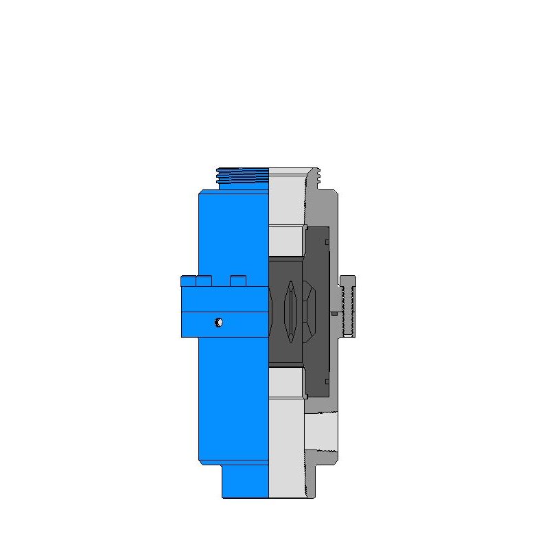
The surface controlled annular gas vent valve is mounted on a Novomet electric submersible pump (ESP) packer. In most operations, the packer isolates the wellhead from an unexpected build-up of gas separated by the ESP gas handling system. When the operator is ready to deal with gas at the surface, hydraulic pressure is applied to the valve. This releases the trapped gas, which will then migrate to the surface for controlled release and disposal. For enhanced safety and performance, the gas vent valve is installed at the top of the ESP packer on the second or third bypass line. Any gas build-up below the packer can be vented into the annulus above the packer by applying pressure to a ¼-in. (6 mm) hydraulic control line. The gas vent valve is fully compatible with all Novomet ESP packers.
Of all the challenges you face keeping your customers’ plants operating at full capacity, safety and relief valves shouldn’t be one of them. NASVI’s job is to give you the confidence that your valve supply chain is rock solid regardless the pressure it’s under.

The tubing-retrievable subsurface safety valve (SSSV) provides well protection against pressure drop and system failure in wireline and thru-tubing operations. This retrievable safety valve is controlled from the surface with a hydraulic control line. The valve connects to the tubing string and remains open if adequate pressure is maintained. If pressure drops below the threshold (as occurs in the beginning stages of losing well control), the valve closes. This creates a barrier in the tubing to prevent fluids from rushing up the tubing.
Introduction to Safety Valves . . . . . . . . . . . . . . . . . . . . . . . . . . . . . . . . . . . . . . . . . . . . . . . . . . . . . . . . . . . . . . . . . . 6
Annular Model WA(E)-5 . . . . . . . . . . . . . . . . . . . . . . . . . . . . . . . . . . . . . . . . . . . . . . . . . . . . . . . . . . . . . . . . . . . . 39
This invention relates to surface controlled subsurface safety valves used in the oil and gas industry and particularly to hydraulically operated valves with small piston areas and metal-to-metal seal systems.
It is common practice to complete oil and gas wells with a casing string partially defining the wellbore and a production tubing string installed within the casing string to conduct fluid flow between the well surface and selected downhole locations. Some well completions are designed to allow fluid flow in the annulus region between the exterior of the production tubing string and the interior of the casing string. Safety valves are frequently installed at selected downhole locations in the wellbore to block fluid flow through the production tubing string and/or the well annulus in the event of an emergency or dangerous conditions at the well surface. Various well completions with alternative casing and production tubing configurations will be discussed later in this written description. The present invention is not limited to use in only oil and gas producing wells and can be used in geothermal wells, injections wells, and any other well with annulus fluid flow requiring a safety system to control such fluid flow.
The present invention is applicable to downhole safety systems having a subsurface safety valve controlled from the well surface to block fluid flow in the well"s production tubing string and another subsurface safety valve controlled from the well surface to block fluid flow in the annulus between the casing and tubing string. Generally, such valves are controlled in response to hydraulic fluid pressure conducted to the respective valve from a remote location at the well surface via small diameter conduits, commonly called control lines. Hydraulic fluid in the control line is used to open and close the safety valves to permit fluid flow through the production tubing string, the well annulus, or both and to selectively block or shut in fluid flow as well conditions require. Surface controllers are typically equipped to respond to emergency conditions such as fire, blowouts, broken flow lines, oil spills, etc.
Examples of prior annulus safety systems are described in U.S. Pat. No. 4,049,052 "Subsurface Annulus Safety Valve"; Canadian Patent 117092 "Well Valve" and German Patent No. P 35 41 826. The present invention uses design features such as rod piston actuators shown in U.S. Pat. No. 4,049,052 and German Patent No. P 35 41 826. Copending U.S. Pat. application Ser. No. 07/726,312 filed on Jul. 5, 1991 is directed towards an improved rod piston actuator and seal assembly which can be used with safety valves of the present invention. The present invention resulted from efforts to improve the downhole reliability and flow characteristics of annulus safety valves. Other annulus safety systems are also shown in:______________________________________
For some well completions, it is desirable to install one or more downhole safety valve at deep depths. For these deep well completions a small piston area is one way to minimize the effect of hydrostatic fluid pressure in the control line leading from the well surface to the downhole valve. Pistons having a small cross section in comparison to the cross section of the complete valve assembly have been used in surface controlled subsurface safety valves. Examples of such pistons are shown in:______________________________________
Since a tubing retrievable safety valve cannot be easily removed from the well bore for routine maintenance, any failure of a fluid seal or accumulation of debris within the safety valve can be very expensive to correct. All sealing systems are subject to failure depending upon the operating environment and design of the seals. For some environments metal-to-metal seals produce longer life as compared to elastomeric materials. Elastomeric, polymeric, and metal-to-metal seal systems have been used in SCSSV"s. Examples of metal-to-metal seal systems are shown in:______________________________________
Any of the subsurface safety valves shown in the above referenced patents which control downhole fluid flow through a tubing string could be used with the present invention. U.S. Pat. No. 4,945,993 entitled SURFACE CONTROLLED SUBSURFACE SAFETY VALVE shows a tubing safety valve which is planned for use with the annulus safety valve of the present invention.
The present invention relates primarily to a safety system for a well having a casing string which partially defines the well bore and a tubing string disposed within the casing string.
A major component of the safety system is an annulus flow safety valve having a housing connectable with the tubing string and a longitudinal bore through the housing to communicate well fluid flow via the tubing string. The exterior of the tubing string and the interior of the casing string partially define an annulus region in the wellbore which can communicate fluid flow in addition to fluid flow through the tubing string.
A valve closure means is mounted on the exterior of the annulus safety valve housing for movement between a first, closed position and a second, open position. A hydraulic actuator in the housing controls movement of the valve closure means between its first position and its second position. The hydraulic actuator normally moves in response to control fluid pressure acting on a small diameter piston and a spring biasing the actuator and valve closure means to move in opposition to control fluid pressure. The valve closure means is used to control fluid flow through the well annulus region.
The present invention allows the use of either metal-to-metal seals or elastomeric seals as part of the hydraulic actuator and the valve closure means as required for optimum performance of the safety system in any specific downhole environment. The net result is a subsurface safety system with increased downhole service life even though well fluids controlled by the safety system may be harmful to some sealing systems.
The annulus flow safety valve of the present invention includes a plurality of flow paths through the annulus safety valve housing and seal means on the exterior of the housing to direct annulus fluid flow through the flow paths. The flow paths have enlarged cross sectional areas to accommodate high fluid flow rates which are frequently required by high volume gas lift wells. Prior annulus safety valves generally used drilled cylindrical flow passageways. The flow paths in the annulus safety valve of the present invention are formed by machining longitudinal slots through the valve housing. The present invention allows the use of electrical discharge machines (EDM) to form the enlarged flow paths in an efficient and cost effective manner.
It is a principal object of the present invention to provide a subsurface safety valve for use at greater depths in oil and gas wells which minimizes the possibility for sand or other debris to hinder prope functioning of the safety valve and maximizes fluid flow when the valve is open.
It is another object of the invention to provide a subsurface safety valve having a valve closure means with metal-to-metal seals and improved piston means which minimizes the number of potential fluid leakage paths. The present invention has metal-to-metal seal which blocks well fluids from entering the control line when the safety valve is in its closed position.
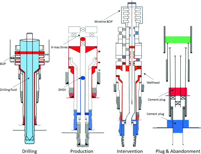
FIGS. 1A and 1B are schematic views in section and elevation of a typical well completion with a downhole safety system including a tubing safety valve and an annulus safety valve and associated tubing string releasably engaged with a casing nipple or a hanger nipple.
FIG. 2 is a schematic view in section and elevation of a typical well completion with a downhole safety system including the annulus safety valve of FIG. 1 and associated tubing string releasably engaged with a well packer or a hanger packer designed for use with annulus safety systems.
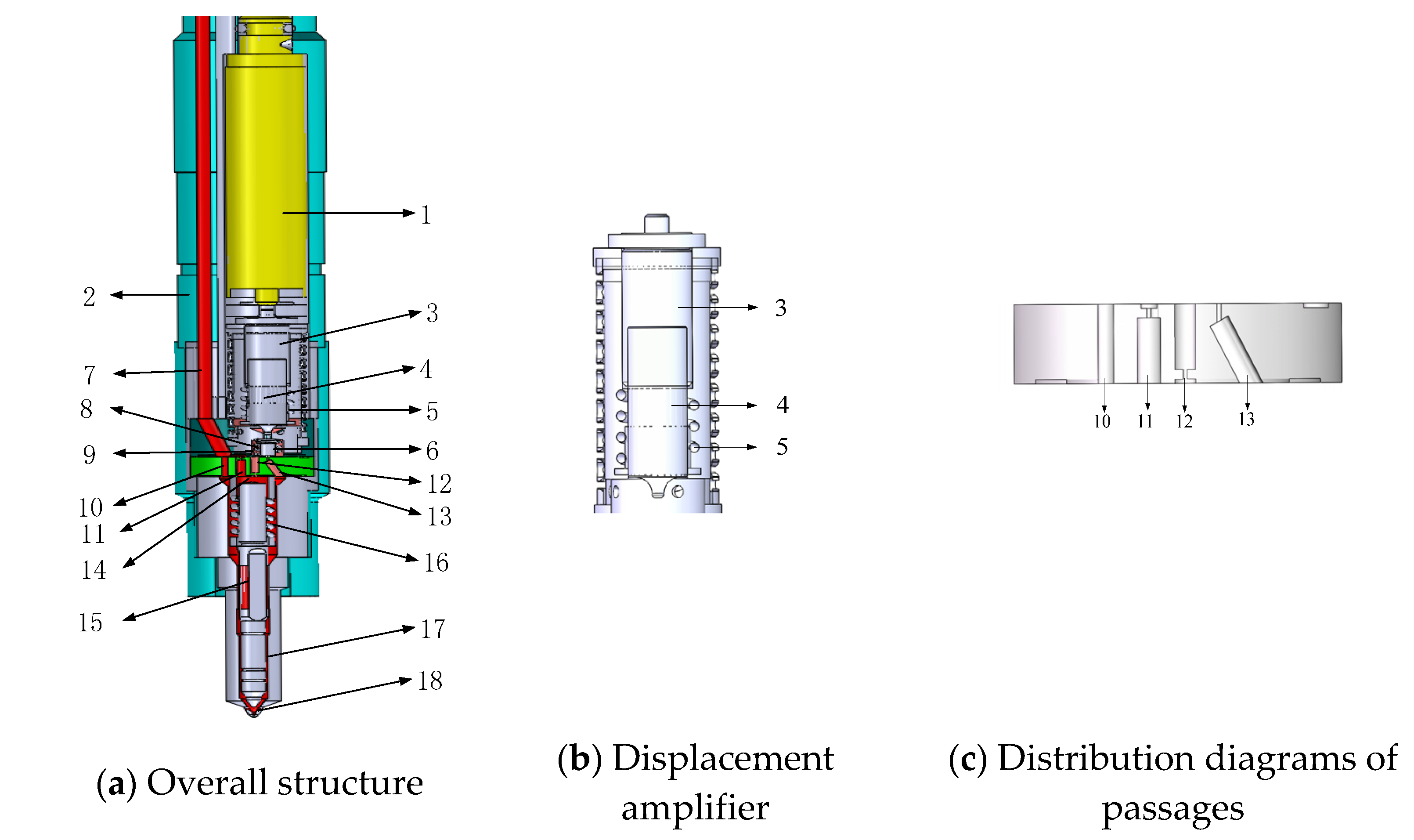
FIGS. 3A and 3B taken together form a longitudinal view in section with portions broken away of the annulus safety valve shown in FIGS. 1 and 2 with the annulus safety valve in its closed position.
FIG. 4A is an enlarged drawing in longitudinal section with portions broken away of the annulus safety valve in FIG. 3A showing its small diameter piston type hydraulic actuator and valve closure means in their closed position.
FIG. 4B is an enlarged drawing in longitudinal section with portions broken away of the annulus safety valve in FIG. 3A showing its small diameter piston type hydraulic actuator and valve closure means in their open position.
FIG. 6 is an enlarged view in section with portions broken away showing an improved valve closure means with metal-to-metal seals for use with the annulus safety valve of FIGS. 1 through 5.
As shown in FIGS. 1A and 1B, a travel joint 24, a surface controlled subsurface safety valve, used as a tubing safety valve 25 and an annulus safety valve 40 embodying features of the present invention are installed in the well completion 20 as part of the tubing string 22. A casing nipple 26 is installed in the casing string 21 at a selected downhole location. The casing nipple 26, sometimes referred to as a hanger nipple, provides a portion of the means for releasably anchoring the safety valve 40 at the selected downhole location, means for forming a fluid barrier to direct annulus fluid flow through the safety valve 40 and means to support at least part of the weight of the tubing string 22 extending below the safety valve 40. Threads 31 are provided on the lower end of the casing nipple 26 to attach a sufficient length of casing string 21 to reach the desired downhole location. In the same manner threads 32 are provided on the lower end of the safety valve 40 to allow the attachment of a sufficient length of production tubing 22 to reach the desired downhole location.
The casing nipple 26 and the annulus safety system packer 200 perform similar functions with respect to the annulus safety valve 40 of the present invention. The annulus safety system packer 200, shown in FIG. 2, will be described in more detail in the Alternative Embodiment section of this written description. The casing nipple 26 includes means for releasably anchoring the safety valve 40 therein such as locking grooves or threads machined in its inside diameter. A releasable anchoring means 33 may or may not be used depending upon well conditions, operating requirements for the safety valve 40, and other components associated with the tubing string 22. As shown in FIG. 1B, the casing nipple 26 also includes a no go shoulder 29 formed on its inside diameter. The releasable anchoring means 33 and no go shoulder 29 are shown spaced longitudinally apart from each other with a polished bore 34 therebetween. The location of these components in the casing nipple 26 can be varied to accommodate alternative configurations of the safety valve 40. The polished bore 34 is provided on the inside diameter of the casing nipple 26 adjacent to the locking means 33 to form a fluid barrier with a seal means 48 carried on the exterior of the safety valve 40.
In FIG. 1B, a fluted hanger assembly 37 is shown attached to the lower end of the safety valve 40. A plurality of longitudinal ribs 38 are provided on the exterior of the fluted hanger assembly 37 to rest on the no-go shoulder 29 and to form longitudinal flow paths 38a to allow the annulus fluid flow past the no-go shoulder 29 when the safety valve 40 and the tubing string 22 are resting thereon.
A surface controlled subsurface safety valve 25, sometimes referred to as a tubing retrievable safety valve, controls fluid flow to the well surface via the tubing string 22 from the producing formation. The safety valve 25 is operated by control fluid conducted from a hydraulic manifold, not shown, at the well surface via a control line 27 which directs control fluid signals to the safety valve 25. A similar control line 28 is provided to direct control fluid to the safety valve 40.
The hydraulic manifold generally includes pumps, a fluid reservoir, accumulators, and control valves for the purpose of providing control fluid pressure signals to hold the safety valves 25 and 40 open or to allow the safety valves 25 and 40 to close when desired. The hydraulic manifold also includes apparatus which functions in response to temperature, surface flow line leaks, and other emergency conditions which require shutting in the well 20. A wide variety of tubing retrievable safety valves are commercially available for use as a safety valve 25. Therefore, the safety valve 25 will not be described in any further detail.
A safety valve 40 as shown in FIGS. 3 through 6 can be generally described as a surface controlled subsurface safety valve with an annular type poppet valve closure means 60.
The valve closure means 60 comprises a cylindrical collar slidably disposed on the exterior of the housing means 41 and biased towards its first, or closed, position by spring 39.
The safety valve 40, as shown in its first or closed position in FIGS. 3A and 4A, can block undesired fluid flow through the annulus 23. The safety valve 40 in its second or open position, as shown in FIG. 4B, allows fluid flow through the annulus 23. A control line 28 directs control fluid pressure from the well surface to a piston means or hydraulic actuator 70. When a predetermined pressure signal is applied to the safety valve 40 through the control line 28 from the well surface, the valve closure means 60 is maintained in its second, open position. When control fluid pressure is released from the piston means 70 a biasing means or a spring 39 can return the valve closure means 60 to its first, closed position.
As shown in FIGS. 3A and 3B safety valve 40 includes a housing means 41 formed by housing subassemblies 42, 43, and 44 which are suitably interconnected by threaded joints 45. Subassemblies 42, 43, and 44 could be interconnected by welded joints or by a combination of threads and elastomeric seals. Welding is sometimes unsatisfactory due to requirements for heat treating the housings before and after welding. Elastomeric seals have a tendency to fail during pressure transients when exposed to certain down hole well environments such as high pressure and/or high temperature gas. Threaded joints 45 are often preferred because they have mechanical strength comparable to a welded connection and provide a metal-to-metal seal.
The housing means 41 can be generally described as a long thick walled cylinder with a longitudinal bore 46 extending therethrough. The ends of housing subassemblies 42 and 44 may be internally or externally threaded to provide means on opposite ends of the housing means 41 for connection with the tubing string 22. The dimensions for the longitudinal bore 46 are selected to provide a relatively unrestricted flow path for fluid communication through the tubing string 22. Movement of the valve closure means 60 between its first and second positions does not open or close the longitudinal bore 46. Fluid flow through the longitudinal bore 46 is directly controlled by the tubing safety valve 25. Closing the annulus safety valve 40 may indirectly effect fluid flow through the longitudinal bore 46 if annulus fluid is used to assist fluid flow from the formation to the well surface via the tubing string 22.
Most of the main components which comprise the annulus safety valve 40 are provided by or attached to housing subassembly 43. These components include an enlarged outside diameter portion 43a with a plurality of arcuate, oval or eliptical slots 47 machined therethrough. Seal means 48, which are positioned intermediate the openings of the oval slots 47, are carried on the exterior of the enlarged diameter portion 43a to coact with an appropriately sized polished bore to form a fluid barrier. A portion of the inside diameter of the casing nipple 26 or the hanger packer 200 provide the required polished bore. Both the casing nipple 26 and the hanger packer 200 provide a polished bore receptacle to both releasably anchor the safety valve 40 at the desire downhole location and to establish the required fluid barrier to direct annulus fluid flow through slots 47. Electrical discharge machines (EDM) and related manufacturing techniques are preferably used to form the slots 47. The use of EDM results in an optimum or maximum flow area through the slots 47 while retaining the required mechanical strength for the housing subassembly 43. The use of EDM also minimizes manufacturing costs. EDM equipment and procedures are available from several companies. A Hitachi Ultra-Cut Series bridge type wire electrical discharge machine is satisfactory for manufacturing the present invention. The upper end 43c of housing subassembly 43 as shown in FIG. 5 demonstrates the increased flow area achieved by using the slots 47 which have been cut using EDM equipment.
The enlarged diameter portion 43a of the housing subassembly also contains a variable volume piston chamber 50 which is offset from the longitudinal bore 46, with a piston means 70 slidably disposed therein. A threaded connector 51 is used to attach the control line 28 to the safety valve 40. Control fluid pressure signals are communicated from the well surface via the control line 28 and the threaded connector 51 to the piston chamber 50. The piston chamber 50 is machined in the wall of the enlarged diameter portion 43a of the housing subassembly 43 parallel with and offset from the longitudinal bore 46. As best shown in FIG. 5, the slots 47 provide a relatively large flow area as compared to the total cross sectional area of the enlarged diameter portion 43a and the piston chamber 50 provides a relatively small cross sectional area as compared to the total cross sectional area of the enlarged diameter portion 43a. The inside diameter 51a of the threaded connector 51 is smaller than the inside diameter 52 of the piston chamber 50. This change in diameters creates a seating surface 53 therebetween.
The piston means 70, or hydraulic actuator, is slidably disposed within the piston chamber 50 to shift the valve closure means 60 from its first, closed position to its second, open position. The piston means 70 has two main components: a piston seal assembly 71 and a piston rod 90.
The configuration of the seal assembly 71 within the piston chamber 50 results in only one possible leak path for annulus fluids to enter the control line 28 when the safety valve 40 is closed. This leak path is blocked by the engagement of the metal-to-metal seating surfaces 53 and 75 when the safety valve 40 is closed as shown in FIG. 4A. Springs 81 or Belville washers assist in maintaining this metal-to-metal seal when there is only a small difference between the control fluid pressure and the annulus fluid pressure. It is important to note that annulus fluid pressure would only be present at the seating surfaces 53 and 75 if the valve closure means 60 was also leaking. Normally, the valve closure means 60 blocks annulus fluid from the piston chamber 50 when the safety valve 40 is in its closed position.
The piston rod 90 extends longitudinally from the lower end of the piston chamber 50 and is mechanically attached to the valve closure means 60. The metal seating surface 92, provided on the exterior of the piston rod 90, forms a metal to metal seal with the reduced inside diameter 54 of the piston chamber 50 when the safety valve 40 is in its open position.
During assembly of the safety valve 40, the piston rod 90 and the piston seal assembly 71 are inserted into the piston chamber 50 prior to installation of the control line connector 51. Attaching control line connector 51 to the piston chamber 50 traps the piston seal assembly 71 between the metal seating surfaces 53 and 54. These metal seating surfaces define the limit of travel of the piston means 70 within the piston chamber 50.
A reduced diameter portion 93 is provided on the lower end of the piston rod 90 extending from the piston chamber 50. The reduced diameter portion 93 provides part of the means for attaching the valve closure means 60 to the piston means 70. The valve closure means 60 is a relatively short, thick walled cylinder with two passageways 62 and 63 extending longitudinally therethrough. Passageway 62 has a large inside diameter 62a and is sized to slide over the exterior of the housing subassembly 43.
When the safety valve 40 is assembled, the valve closure means 60 and the passageway 62 are concentric with the housing means 41 and the longitudinal bore 46. The passageway 63 is formed in the wall of the valve closure means 60 and has two different inside diameter portions 63a and 63b. This change in inside diameter forms a shoulder 64 intermediate the ends of the passageway 63. The inside diameter portion 63a is sized to receive the reduced diameter portion 93 of the piston rod 90. The inside diameter portion 63b which is larger than the inside diameter portion 63a is sized to receive a locking nut 94. Therefore, after the piston means 70 has been assembled in the piston chamber 50, the valve closure means 60 can slide over the exterior of the housing subassembly 43 to insert the piston rod portion 93 into the passageway 63. The locking nut 94 is then installed through the inside diameter portion 63b to secure the valve closure means 60 with the piston means 70. Assembly is completed by next inserting springs 81 in the inside diameter portion 63b followed by the end cap 64 which closes the passageway 63.
A spring 39 is carried on the exterior of the housing means 41 between a shoulder 143 on the enlarged outside diameter portion 43a and the housing subassembly 44 and abuts the lower end of the valve closure means 60. A sleeve 139 is also carried on the exterior of the housing means 41 to protect the spring 39 during installation of the safety valve 40 into the casing nipple 26 or the hanger packer 200.
An important feature of the valve closure means 60 is the metal seating surface 65 formed on the end of the valve closure means 60 which contacts the enlarged outside diameter portion 43a when the safety valve 40 is closed. The metal seating surface 65 is preferably convex with a radius to match a similar concave seating surface 49 on the enlarged outside diameter portion 43a of the housing means 41. By properly selecting the radius for seating surfaces 65 and 49, a fluid tight metal-to-metal seal will be established when the valve closure means 60 is in its first position. This metal to metal seal blocks annulus fluid flow through the slots 47. For increased service life, the metal seating surface 65 may be hard faced by various metallurgical procedures.
For some well completions a hanger packer 200 may be used in place of the casing nipple 26. The use of a hanger packer 200 allows the upper portion 22a of the tubing string 22 including the safety valve 40 to be retrieved from the well bore while the packer 200 and the lower portion 22b of the tubing string 22 remains installed in the casing 21. The hanger packer 200 includes a plurality of slips 201 to anchor the packer 200 to the interior of the casing string 21 at the desired downhole location. Packer sealing elements 202 are provided on the exterior of the packer 200 to prevent undesired annulus fluid flow between the packer 200 and the casing string 21 after the slips 201 have anchored the packer 200 at the desired downhole location. A plurality of flow ports 203 are provided in the packer 200 to direct annulus fluid communication through the safety valve 40. Various combinations of locking grooves, threads, no-go shoulders and similarly known mechanism may be used to releasably anchor the safety valve 40 within the hanger packer 200 if required by downhole well conditions.

SSSV: Subsurface Safety Valve: a valve installed in the tubing down the well to prevent uncontrolled flow in case of an emergency through the tubing when actuated. These valves can be installed by wireline or as an integral part of the tubing. Subsurface Valves are usually divided into the following categories.
SCSSV: Surface-Controlled Subsurface Safety Valves: SSSV which is controlled from the surface and installed by wireline or as an integral part of the tubing.
SSCSV (storm choke): Subsurface-Controlled Subsurface Safety Valve: SSSV which is actuated by the flow characteristics of the well, and is wireline retrievable.
ASV: Annulus Safety Valve: a valve installed in the well to prevent uncontrolled flow in the casing-tubing annulus when actuated. It consists of an annular safety valve packer with a by-pass. The opening in the by-pass is controlled by a safety valve, which can be an integral part of the packer on a wireline retrievable valve.
The tubing safety valve is installed to provide a flow barrier in the production tubing string, between the tail pipe and the surface or mudline. Such a valve consists of 3 main items:
Safety valve should not be considered as an extra barrier in the tubing when the well is closed-in for a long period of time. Sealing is not optimal because of design space limitations. They should not be used to regularly shut-in the well.
The annulus safety valve (ASV) provides a flow barrier in the casing-tubing annulus. It consists of an annular safety valve packer with a by-pass. The opening of the by-pass is controlled by a safety valve, which can be an integral part of the packer or a wireline retrievable valve. It is a surface controlled, fail-safe closed device for annular flow.
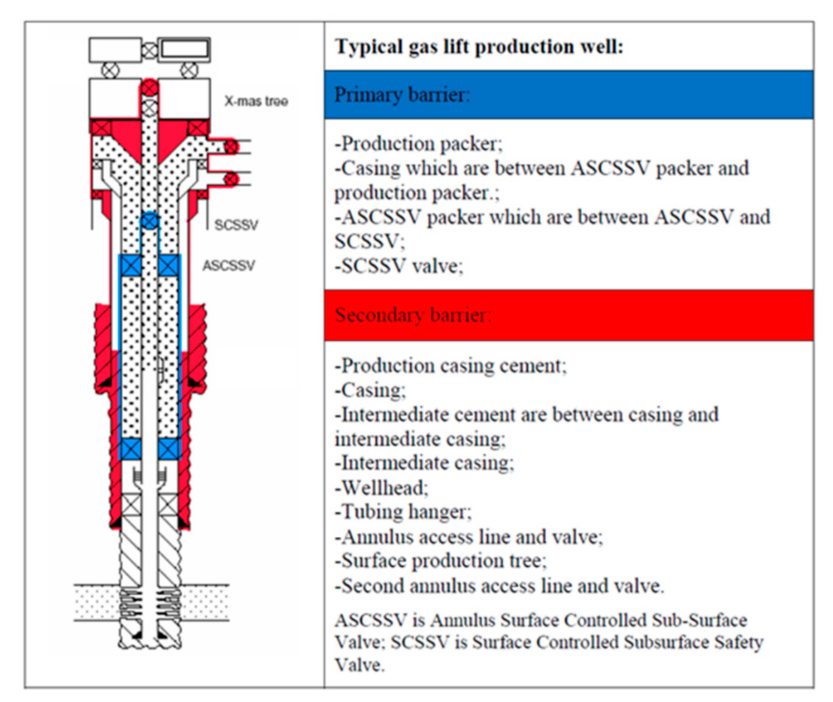
In general, the ASV is installed in gas lifted wells where the annulus is filled with compressed gas and serves as a barrier. Because of gas lift valves, the tubing cannot be considered as a barrier between the reservoir and the surface. Although the gas lift valves are commonly equipped with check valves, they are not a valid barrier. The ASV is normally located at a shallow depth to reduce the volume of the gas stored in the annulus between the ASV and the wellhead.
The valve body and connections should be at least as strong as the tubing. It should provide leak resistance to internal and external pressures and be compatible with the fluids.
During the installation of the tubing string, it is necessary to keep the valve open. This can be done by inserting a retrievable lock-open tool in the valve, without or in combination with the control signal from surface.
Multiple zone completions, where wireline jobs are frequent on equipment installed beneath the safety valve. The larger bore of a TR-SSSV facilitates the operations, where a WR-SSSV normally has to be retrieved.
The wireline retrievable safety valve (WR SCSSV) is run on wireline. A lock mandrel is screwed on top of the WR SCSSV that enables using a landing nipple. This nipple must hold the valve/mandrel assembly against pressure differentials loads. The nipple has a polished bores to seal the path between WR SCSSV and landing nipple by seals fitted to the outside of the valve/mandrel assembly.
With hydraulically operated WR SCSSVs, the external seals have also the function of containing the control fluid that is to be transmitted to the valve actuator.
The landing nipple for an electrically operated valve has a connection for an electric control line and an inductive coupler to transmit the signal to the WR SCSSV.
Trough Flowline retrievable safety valves use specially constructed mandrels and landing nipples. They must have a stronger hold-open force than SCSSVs, because the Trough Flowline tools are circulated upwards in the tubing string, which tends to drag the valve"s flow tube up, causing the valve to close. To overcome this problem the actuator hold-open force should be higher than the sum of the normal hold open force and the drag forces that can be experienced. Trough Flowline retrievable SSSVs can be used for subsea completions where wireline operations are difficult.
Another application is to install a SSSV in tubing without a landing nipple. Such a system consists of a production packer with an integral safety valve. The assembly is positioned by the coiled tubing and the packer is set by pressure from the coiled tubing.
Subsurface controlled valves are normally open and are designed to close with an abnormal change in well condition. They detect the flow or well pressure and close when the set limit is reached. Basically there are three different concepts:
Surface controlled valves utilise valve elements that are normally closed. This fail-safe mode requires that the valve is to be opened by a hydraulic control-line pressure. Loss of this pressure will result in the closing of the valve by a spring. The hydraulic pressure is supplied from a surface control panel to the valve and acts on the actuator. Typical for hydraulic operated SCSSVs is the hydrostatic head pressure, generated by the vertical column of control fluid, which additionally acts on the valve actuator.
the surface control line pressure and the time for valve operation will give an indication whether the valve opening and closing performance is satisfactory;
TR-SCSSVs of which the hydraulic actuator is damaged can be put back into function by inserting a back-up valve (insert valve), which can be operated with the existing hydraulic control system;
Electrically operated SCSSVs have in common with hydraulic SCSSVs that the differential pressure over the closed valve must be equalised before the valve can be opened and a means to keep the valve open must be permanently available from surface for fail safe operation.
With electric valves that means is an electrical signal, either dc or ac. Loss of this signal will result in closing of the valve. The force to close is always provided by expanding steel springs, which are precompressed by either electric power or by the well pressure.
One type of mechanically operated SSSV is the Go-Devil valve from Otis. This safety valve is a normally open valve. It is designed to close by an impact force on the head of the valve, provided by a heavy ball that is dropped from a ball-dropper assembly at surface. The impact force will activate the spring based mechanical linkage, that moves the valve to the closed position.
The ball-dropper assembly is flange mounted on top of the Christmas tree. The pocket of the ball dropper retains the ball, sized to activate the Go-Devil SSSV by falling against flow and impacting the head of the valve. The ball dropper assembly retains the ball until the loss of the control signal activates the release mechanism.
Three types of valve closure elements are commonly used for SSSV: the ball, the flapper and the poppet type. The flapper valve can further be divided in flat, contoured and curved flappers, while the poppet valve can be divided into closed body and sleeve type poppet valves. All types of closure elements pinch off the fluid stream by a pair of opposing surfaces rather than sliding surfaces. This principal method has the advantage that it can provide a good tight shut-off when the sealing surfaces are sound.
As noted the flapper valves may be flat, curved or contoured. The latter two were introduced to obtain a better OD/ID ratio, as they are shaped to fit when in the open position, more efficiently in the annular space of the valve housing.
The seat angle is the shape of the flapper sealing surfaces, which is an important parameter of the valve sealing performance. Traditional flapper valves have a seat angle of 45°, as the angled seat has the advantage that:
Due to the characteristics of the curved flapper design the seat angle may vary from 0° to 60° along the flapper circumference, thus requiring stringent alignment of the sealing faces. The contoured flapper design has an angled sealing surface over the full circumference of the flapper and thus has potential to provide good sealing. Field experience indicate that the flapper valve type is more reliable than the ball valve type.
When a SSSV is closed, a high differential pressure may be present across the valve closure element. Opening the valve under this condition will be difficult, if not impossible, because of the incapability of the relatively small valve mechanism to cope with the load working on the large diameter closure element. Insufficient equalising will introduce high loads that could deform critical valve parts. Also, erosive wash-out on the closure element by the sudden rush of well fluid through the partly opened valve can occur. Therefore, prior to opening a SSSV it is necessary to equalise the differential pressure.
The depth at which to set the subsurface safety valve depends upon a number of variables, such as hydrate and wax formation tendencies, deviation kick-off depth, scale precipitation, earthquake probabilities, etc. The OD of the safety valve may influence the casing/tubing string configuration and should be addressed at the conceptual design stage.
For tubing safety valves it is obvious that the deeper the valve is set (closer to the hydrocarbon source) the more protection it will give to the completion. However, the application of a deep-set tubing SSSV generates some unfavourable conditions, namely:
the higher temperature further downhole effects the reliability and the longevity of non-metal valve parts, for instance polymeric seals in hydraulic valves and electric/electronic parts in electric valves;
the hydrostatic head pressure generated by the hydraulic control-line column will generate excessive forces on the valve operating mechanism. Hence, designing and manufacturing of these valves becomes more complicated.
Furthermore, the required control pressure to operate a single control line valve (the majority of SSSVs) could become too high and more than the pressure rating of standard well completion equipment.
The approach for determining the required hydraulic control pressure at surface to hold a valve open depends on the type of valve, viz. the single control line valve, the dual control line valve and the valve with a pressure chamber.
Due to friction in the valve mechanism and the spring characteristic, there is a certain spread between the valve opening pressure (Pvo) and closing pressure (Pvc).
To ensure that the valve is completely open, a safety factor or pressure margin (Pm) is added to the surface control pressure. Hence, the available control pressure at surface to open the valve must be at least:
The dual control line valve or the pressure balanced valve uses a second control line from surface to balance the generated hydrostatic head pressure in the control line. The forces acting to operate this type of valve are as follows:
Due to friction in the valve mechanism and the spring characteristic, there is a certain spread between the valve opening pressure (Pvo) and closing pressure (Pvc).
When the valve is in the fully open position and the control and the balance line are both filled with fluid of the same fluid gradient, the following force equilibrium exists:
To insure that the valve is completely open, a safety factor or pressure margin (Pm) is added to the surface control pressure. Hence, the available control pressure at surface to open the valve must be at least:
The dome charged valve uses a pressure in an integral dome to (partly) balance the generated hydrostatic head pressure in the control line. The forces acting to operate this type of valve are as follows:
Due to friction in the valve mechanism and the spring characteristic, there is a certain spread between the valve opening pressure (Pvo) and closing pressure (Pvc).
To ensure that the valve is completely open, a safety factor or pressure margin (Pm) is added to the surface control pressure. Hence, the available control pressure at surface to open the valve must be at least:
The theoretical maximum setting depth of a single control line SSSV depends on the capacity of the valve closing spring to overcome the generated hydrostatic head pressure in the control line. For fail safety it is essential that the tubing pressure is not taken into account for the assistance of valve closing, even though single control line valves are assisted by this pressure. Hence, the governing factors for the maximum valve setting depth are:
* For fail safety, the worst case must be assumed, one in which the control line ruptures near the valve and annulus fluid will enter the control line. Therefore, for any completion the heaviest fluid gradient, either from the control fluid or from the annulus fluid, is used as the minimum control line fluid gradient.
Because the hydrostatic head pressure in the control line is counteracted, the setting depths of the dual control-line and the dome-charged valves are theoretically not limited.

A downhole safety valve refers to a component on an oil and gas well, which acts as a failsafe to prevent the uncontrolled release of reservoir fluids in the event of a worst-case-scenario surface disaster. It is almost always installed as a vital component on the completion.
These valves are commonly uni-directional flapper valves which open downwards such that the flow of wellbore fluids tries to push it shut, while pressure from the surface pushes it open. This means that when closed, it will isolate the reservoir fluids from the surface.
Most downhole safety valves are controlled hydraulically from the surface, meaning they are opened using a hydraulic connection linked directly to a well control panel. When hydraulic pressure is applied down a control line, the hydraulic pressure forces a sleeve within the valve to slide downwards. This movement compresses a large spring and pushes the flapper downwards to open the valve. When hydraulic pressure is removed, the spring pushes the sleeve back up and causes the flapper to shut. In this way, it is failsafe and will isolate the wellbore in the event of a loss of the wellhead. The full designation for a typical valve is "tubing retrievable, surface controlled, subsurface safety valve", abbreviated to TR-SCSSV.
The location of the downhole safety valve within the completion is a precisely determined parameter intended to optimise safety. There are arguments against it either being too high or too low in the well and so the final depth is a compromise of all factors. MMS regulations state that the valve must be placed no less than 30 m (100 ft) below the mudline.
The further down the well the DHSV is located, the greater the potential inventory of hydrocarbons above it when closed. This means that in the event of loss of containment at surface, there is more fluid to be spilled causing environmental damage, or in the worst case, more fuel for a fire. Therefore, placing the valve higher limits this hazard.
Another reason relates to the hydraulic control line. Hydraulic pressure is required to keep the valve open as part of the failsafe design. However, if the valve is too far down the well, then the weight of the hydraulic fluid alone may apply sufficient pressure to keep the valve open, even with the loss of surface pressurisation.
As part of the role of the DHSV to isolate the surface from wellbore fluids, it is necessary for the valve to be positioned away from the well where it could potentially come to harm. This implies that it must be placed subsurface in all circumstances, i.e. in offshore wells, not above the seabed. There is also the risk of cratering in the event of a catastrophic loss of the topside facility. The valve is specifically placed below the maximum depth where cratering is expected to be a risk.
If there is a risk of methane hydrate (clathrate) plugs forming as the pressure changes through the valve due to Joule–Thomson cooling, then this is a reason to keep it low, where the rock is warmer than an appropriately-calculated temperature.
Most downhole safety valves installed as part of the completion design are classed as "tubing retrievable". This means that they are installed as a component of the completion string and run in during completion. Retrieving the valve, should it malfunction, requires a workover. The full name for this most common type of downhole safety valve is a Tubing Retrievable Surface Controlled Sub-Surface Valve, shortened in completion diagrams to TRSCSSV.
If a tubing retrievable valve fails, rather than go to the expense of a workover, a "wireline retrievable" valve may be used instead. This type of valve can fit inside the production tubing and is deployed on wireline after the old valve has been straddled open.
The importance of DHSVs is undisputed. Graphic images of oil wells in Kuwait on fire after the First Gulf War after their wellheads were removed, demonstrate the perils of not using the components (at the time, they were deemed unnecessary because they were onshore wells). It is, however, not a direct legal requirement in many places. In the United Kingdom, no law mandates the use of DHSVs. However, the 1974 Health & Safety at Work Act requires that measures are taken to ensure that the uncontrolled release of wellbore fluids is prevented even in the worst case. The brilliance of the act is that it does not issue prescriptive guideline for how to achieve the goal of health and safety, but merely sets out the requirement that the goal be achieved. It is up to the oil companies to decide how to achieve it and DHSVs are an important component of that decision. As such, although not a legal requirement, it is company policy for many operators in the UKCS.
While the DHSV isolates the production tubing, a loss of integrity could allow wellbore fluid to bypass the valve and escape to surface through the annulus. For wells using gas lift, it may be a requirement to install a safety valve in the "A" annulus of the well to ensure that the surface is protected from a loss of annulus containment. However, these valves are not as common and they are not necessarily installed at the same position in the well, meaning it is possible that fluids could snake their way around the valves to surface.


 8613371530291