
annular safety valve supplier

Annulus control safety valves from Baker Hughes prevent uncontrolled flow in your well’s annular space to ensure that your gas-lift operations run smoothly and safely.
You maintain downhole safety with non-elastomeric technology and a rod piston for long-term sealing durability that withstands high pressures and temperatures. Single control lines actuate the valve while a loss-of-control pressure line provides emergency closure.
Optimize production at lower operating costs. Maximize your well productivity with annulus valves designed with a large annular flow area that minimizes pressure drops
Reduce risk. Ensure safe and reliable operation with annulus safety valves configured to your operating conditions and proven in stringent prototype testing prior to deployment
Wells with planned or unplanned sustained annulus pressure (SAP) pose a considerable risk to personnel and facilities. In these situations, annulus line gate valves (a gasket, bonnet seal or stem seal) are the primary well barrier envelope elements, with no back up in case of failure.
Most O&G companies follow a double barrier well integrity management policy. In wells operated with SAP the single barrier gate valves are in breach of this policy. Annulus line gate valves also significantly increase the ‘footprint’ of the wellhead. They require regular testing, maintenance and occasional replacement, resulting in significant life cycle costs.
The Hydraulic Surface Annulus Safety (HSASTM) valve addresses all of the challenges listed above. It is installed in the wellhead VR profile, where (in wells with SAP) it becomes an independently testable element of the primary barrier envelope.
Surface-controlled subsurface safety valves (SCSSVs) are critical components of well completions, preventing uncontrolled flow in the case of catastrophic damage to wellhead equipment. Fail-safe closure must be certain to ensure proper security of the well. However, this is not the only function in which it must be reliable—the valve must remain open to produce the well. Schlumberger surface controlled subsurface safety valves exceed all ISO 10432 and API Spec 14A requirements for pressure integrity, leakage acceptance criteria, and slam closure.
Through decades of innovation and experience, Schlumberger safety valve flapper systems are proven robust and reliable. The multizone dynamic seal technology for hydraulic actuation of subsurface safety valves is a further improvement in reliability performance when compared with traditional seal systems in the industry.
The multizone seal technology is currently available in the GeoGuard high-performance deepwater safety valves, which is validated to API Spec 14A V1 and V1-H.

Halliburton provides proven, high-performance tubing-retrievable and wireline-retrievable subsurface safety valves (SSSV) designed to reliably shut-in (fail safe) if a catastrophic event occurs, allowing operators to maintain safe operations.

The Halliburton NE™ tubing-retrievable safety valve (TRSV) is a single rod-piston non-elastomer flapper valve designed for general production with enhanced reliability and long life. The valve includes the non-elastomer hydraulic actuator design from the highly reliable SP™ line of safety valves. Along with the metal-to-metal (MTM) body joints and closure mechanism, the actuator places this valve in the premium category while keeping costs economical. The simple, compact design enhances the valve’s overall reliability and provides for trouble-free operation.
Of all the challenges you face keeping your customers’ plants operating at full capacity, safety and relief valves shouldn’t be one of them. NASVI’s job is to give you the confidence that your valve supply chain is rock solid regardless the pressure it’s under.
Introduction to Safety Valves . . . . . . . . . . . . . . . . . . . . . . . . . . . . . . . . . . . . . . . . . . . . . . . . . . . . . . . . . . . . . . . . . . 6
Annular Model WA(E)-5 . . . . . . . . . . . . . . . . . . . . . . . . . . . . . . . . . . . . . . . . . . . . . . . . . . . . . . . . . . . . . . . . . . . . 39

SSSV: Subsurface Safety Valve: a valve installed in the tubing down the well to prevent uncontrolled flow in case of an emergency through the tubing when actuated. These valves can be installed by wireline or as an integral part of the tubing. Subsurface Valves are usually divided into the following categories.
SCSSV: Surface-Controlled Subsurface Safety Valves: SSSV which is controlled from the surface and installed by wireline or as an integral part of the tubing.
SSCSV (storm choke): Subsurface-Controlled Subsurface Safety Valve: SSSV which is actuated by the flow characteristics of the well, and is wireline retrievable.
ASV: Annulus Safety Valve: a valve installed in the well to prevent uncontrolled flow in the casing-tubing annulus when actuated. It consists of an annular safety valve packer with a by-pass. The opening in the by-pass is controlled by a safety valve, which can be an integral part of the packer on a wireline retrievable valve.
The tubing safety valve is installed to provide a flow barrier in the production tubing string, between the tail pipe and the surface or mudline. Such a valve consists of 3 main items:
Safety valve should not be considered as an extra barrier in the tubing when the well is closed-in for a long period of time. Sealing is not optimal because of design space limitations. They should not be used to regularly shut-in the well.
The annulus safety valve (ASV) provides a flow barrier in the casing-tubing annulus. It consists of an annular safety valve packer with a by-pass. The opening of the by-pass is controlled by a safety valve, which can be an integral part of the packer or a wireline retrievable valve. It is a surface controlled, fail-safe closed device for annular flow.
In general, the ASV is installed in gas lifted wells where the annulus is filled with compressed gas and serves as a barrier. Because of gas lift valves, the tubing cannot be considered as a barrier between the reservoir and the surface. Although the gas lift valves are commonly equipped with check valves, they are not a valid barrier. The ASV is normally located at a shallow depth to reduce the volume of the gas stored in the annulus between the ASV and the wellhead.
The valve body and connections should be at least as strong as the tubing. It should provide leak resistance to internal and external pressures and be compatible with the fluids.
During the installation of the tubing string, it is necessary to keep the valve open. This can be done by inserting a retrievable lock-open tool in the valve, without or in combination with the control signal from surface.
Multiple zone completions, where wireline jobs are frequent on equipment installed beneath the safety valve. The larger bore of a TR-SSSV facilitates the operations, where a WR-SSSV normally has to be retrieved.
The wireline retrievable safety valve (WR SCSSV) is run on wireline. A lock mandrel is screwed on top of the WR SCSSV that enables using a landing nipple. This nipple must hold the valve/mandrel assembly against pressure differentials loads. The nipple has a polished bores to seal the path between WR SCSSV and landing nipple by seals fitted to the outside of the valve/mandrel assembly.
With hydraulically operated WR SCSSVs, the external seals have also the function of containing the control fluid that is to be transmitted to the valve actuator.
The landing nipple for an electrically operated valve has a connection for an electric control line and an inductive coupler to transmit the signal to the WR SCSSV.
Trough Flowline retrievable safety valves use specially constructed mandrels and landing nipples. They must have a stronger hold-open force than SCSSVs, because the Trough Flowline tools are circulated upwards in the tubing string, which tends to drag the valve"s flow tube up, causing the valve to close. To overcome this problem the actuator hold-open force should be higher than the sum of the normal hold open force and the drag forces that can be experienced. Trough Flowline retrievable SSSVs can be used for subsea completions where wireline operations are difficult.
Another application is to install a SSSV in tubing without a landing nipple. Such a system consists of a production packer with an integral safety valve. The assembly is positioned by the coiled tubing and the packer is set by pressure from the coiled tubing.
Subsurface controlled valves are normally open and are designed to close with an abnormal change in well condition. They detect the flow or well pressure and close when the set limit is reached. Basically there are three different concepts:
Surface controlled valves utilise valve elements that are normally closed. This fail-safe mode requires that the valve is to be opened by a hydraulic control-line pressure. Loss of this pressure will result in the closing of the valve by a spring. The hydraulic pressure is supplied from a surface control panel to the valve and acts on the actuator. Typical for hydraulic operated SCSSVs is the hydrostatic head pressure, generated by the vertical column of control fluid, which additionally acts on the valve actuator.
the surface control line pressure and the time for valve operation will give an indication whether the valve opening and closing performance is satisfactory;
TR-SCSSVs of which the hydraulic actuator is damaged can be put back into function by inserting a back-up valve (insert valve), which can be operated with the existing hydraulic control system;
Electrically operated SCSSVs have in common with hydraulic SCSSVs that the differential pressure over the closed valve must be equalised before the valve can be opened and a means to keep the valve open must be permanently available from surface for fail safe operation.
With electric valves that means is an electrical signal, either dc or ac. Loss of this signal will result in closing of the valve. The force to close is always provided by expanding steel springs, which are precompressed by either electric power or by the well pressure.
One type of mechanically operated SSSV is the Go-Devil valve from Otis. This safety valve is a normally open valve. It is designed to close by an impact force on the head of the valve, provided by a heavy ball that is dropped from a ball-dropper assembly at surface. The impact force will activate the spring based mechanical linkage, that moves the valve to the closed position.
The ball-dropper assembly is flange mounted on top of the Christmas tree. The pocket of the ball dropper retains the ball, sized to activate the Go-Devil SSSV by falling against flow and impacting the head of the valve. The ball dropper assembly retains the ball until the loss of the control signal activates the release mechanism.
Three types of valve closure elements are commonly used for SSSV: the ball, the flapper and the poppet type. The flapper valve can further be divided in flat, contoured and curved flappers, while the poppet valve can be divided into closed body and sleeve type poppet valves. All types of closure elements pinch off the fluid stream by a pair of opposing surfaces rather than sliding surfaces. This principal method has the advantage that it can provide a good tight shut-off when the sealing surfaces are sound.
As noted the flapper valves may be flat, curved or contoured. The latter two were introduced to obtain a better OD/ID ratio, as they are shaped to fit when in the open position, more efficiently in the annular space of the valve housing.
The seat angle is the shape of the flapper sealing surfaces, which is an important parameter of the valve sealing performance. Traditional flapper valves have a seat angle of 45°, as the angled seat has the advantage that:
Due to the characteristics of the curved flapper design the seat angle may vary from 0° to 60° along the flapper circumference, thus requiring stringent alignment of the sealing faces. The contoured flapper design has an angled sealing surface over the full circumference of the flapper and thus has potential to provide good sealing. Field experience indicate that the flapper valve type is more reliable than the ball valve type.
When a SSSV is closed, a high differential pressure may be present across the valve closure element. Opening the valve under this condition will be difficult, if not impossible, because of the incapability of the relatively small valve mechanism to cope with the load working on the large diameter closure element. Insufficient equalising will introduce high loads that could deform critical valve parts. Also, erosive wash-out on the closure element by the sudden rush of well fluid through the partly opened valve can occur. Therefore, prior to opening a SSSV it is necessary to equalise the differential pressure.
The depth at which to set the subsurface safety valve depends upon a number of variables, such as hydrate and wax formation tendencies, deviation kick-off depth, scale precipitation, earthquake probabilities, etc. The OD of the safety valve may influence the casing/tubing string configuration and should be addressed at the conceptual design stage.
For tubing safety valves it is obvious that the deeper the valve is set (closer to the hydrocarbon source) the more protection it will give to the completion. However, the application of a deep-set tubing SSSV generates some unfavourable conditions, namely:
the higher temperature further downhole effects the reliability and the longevity of non-metal valve parts, for instance polymeric seals in hydraulic valves and electric/electronic parts in electric valves;
the hydrostatic head pressure generated by the hydraulic control-line column will generate excessive forces on the valve operating mechanism. Hence, designing and manufacturing of these valves becomes more complicated.
Furthermore, the required control pressure to operate a single control line valve (the majority of SSSVs) could become too high and more than the pressure rating of standard well completion equipment.
The approach for determining the required hydraulic control pressure at surface to hold a valve open depends on the type of valve, viz. the single control line valve, the dual control line valve and the valve with a pressure chamber.
Due to friction in the valve mechanism and the spring characteristic, there is a certain spread between the valve opening pressure (Pvo) and closing pressure (Pvc).
To ensure that the valve is completely open, a safety factor or pressure margin (Pm) is added to the surface control pressure. Hence, the available control pressure at surface to open the valve must be at least:
The dual control line valve or the pressure balanced valve uses a second control line from surface to balance the generated hydrostatic head pressure in the control line. The forces acting to operate this type of valve are as follows:
Due to friction in the valve mechanism and the spring characteristic, there is a certain spread between the valve opening pressure (Pvo) and closing pressure (Pvc).
When the valve is in the fully open position and the control and the balance line are both filled with fluid of the same fluid gradient, the following force equilibrium exists:
To insure that the valve is completely open, a safety factor or pressure margin (Pm) is added to the surface control pressure. Hence, the available control pressure at surface to open the valve must be at least:
The dome charged valve uses a pressure in an integral dome to (partly) balance the generated hydrostatic head pressure in the control line. The forces acting to operate this type of valve are as follows:
Due to friction in the valve mechanism and the spring characteristic, there is a certain spread between the valve opening pressure (Pvo) and closing pressure (Pvc).
To ensure that the valve is completely open, a safety factor or pressure margin (Pm) is added to the surface control pressure. Hence, the available control pressure at surface to open the valve must be at least:
The theoretical maximum setting depth of a single control line SSSV depends on the capacity of the valve closing spring to overcome the generated hydrostatic head pressure in the control line. For fail safety it is essential that the tubing pressure is not taken into account for the assistance of valve closing, even though single control line valves are assisted by this pressure. Hence, the governing factors for the maximum valve setting depth are:
* For fail safety, the worst case must be assumed, one in which the control line ruptures near the valve and annulus fluid will enter the control line. Therefore, for any completion the heaviest fluid gradient, either from the control fluid or from the annulus fluid, is used as the minimum control line fluid gradient.
Because the hydrostatic head pressure in the control line is counteracted, the setting depths of the dual control-line and the dome-charged valves are theoretically not limited.
The invention relates to an annulus safety valve for use in a subterranean oil and/or gas well and to a method of controlling pressure within an annular area using the safety valve.
Just as safety valves must be provided to selectively sealingly block the interior of the production or workstring so that flow of fluid hydrocarbons from the production zone to the top of the well may be shut off at such safety valve to prevent a "blow out" in the event of an uncontrollable situation, such as fire, or the like, so the well "annulus" must likewise be controlled if it is exposed to a second production zone or is to be used for injection of fluid for one reason or another from the top of the well to a given production zone within the well.
While annulus safety valves have been utilized in the art, none are "full opening", so the internal diameter of such safety valve components for the annulus is not substantially equal to the internal diameter of the production or workstring, such that tools carried on remedial coiled tubing, wire or electric line, may safely and completely pass therethrough without any interference to longitudinal and/or rotational movement.
As set forth above, the purpose of such annulus safety valves herebefore utilized has been to control well pressure below such valves from communicating the tubing/casing annulus across such valves. It would be desirable to provide control of the annulus, yet permit selective injection of chemical inhibitor, kill fluid, and the like within the annular area between the tubing and casing from above the annulus safety valve to the area therebelow and within the interior of the casing on a selective volumetric basis.
Furthermore, it would be desirable to permit increased fluid flow across such annulus safety valve, selectively, merely by increase of fluid pressure within the tubing casing annulus above the annulus safety valve by permitting plug means which may be shearingly removed from sealing engagement within the valve to permit increase in fluid flow therethrough, such plug means also being replaceable by additional valve head and seat members of the same design and operation as other valve head and seat members forming the annulus safety valve.
The present invention addresses the above-identified problems and provides a unique annulus safety valve as described below and in the drawings incorporated herein.
The present invention provides a subterranean well annulus safety valve for control of fluid flow between outer and inner tubular conduits concentrically disposed within the well, said conduits extending from a first end of the safety valve to a point in the well.
The annulus safety valve comprises a cylindrical central housing securable to the inner of said tubular conduits. A fluid flow passageway is defined through the central housing and is in fluid flow communication with the interior of the inner of the tubular conduits.
Control valve means include valve head seat members which are disposed in the second housing with the head and seat members being in normally closed position to prevent fluid between the outer and inner tubular conduits from flowing through the central valve means, with the head and seat members being movable relative to one another to permit fluid flow through the control valve means.
The apparatus also includes, in one embodiment, a ported housing with a series of ports defined therethrough and circumferentially extending around the housing and at least one of the ports receiving the valve head and seat means.
The apparatus also includes pressure equalizing means within the ported second housing which is selectively movable while the valve head and seat means are in closed position from a first closed and sealed position to a second open pressure equalizing position to thereby equalize pressure across the valve head and seat means and the exterior of the central housing.
In the preferred embodiment, there is provided a series of valve head and seat members, with the valve head and seat members including members thereon to initiate movement of each of the valve head and seat members in sequence from a normally closed position to permit fluid flow therethrough in response, preferably, to varied application of pressure thereacross as well as when well pressure upstream of the members is greater than pressure downstream of such members.
As used herein, both in the claims and in the specification, the term "normally closed" means the position at which the valve head and seat members are located when there is no pressure differential thereacross.
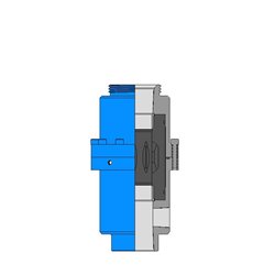
FIG. 1 is a longitudinal section schematic illustration of a well incorporating the annulus safety valve system of the present invention, in schematic view.
FIGS. 3, 4, and 5 together are a more detailed view of the valve of FIG. 2, in one-quarter longitudinal section view, with FIG. 3 representing the uppermost portion of the valve, FIG. 4 representing the middle portion of the valve, and FIG. 5 representing the lowermost portion of the valve.
The end opposite the opening 123a of the ported second housing 105 defines a circumferentially subscribed angularly beveled metallic valve seat 107 for companion receipt of a valve head end 108a of a valve head member 108. These valve head and seat members are normally biased to the closed position, but are selectively openable upon either application of pressure through the opening 123a into the passage 123 from the top of the well, or, more preferably and conventionally, by means of application of hydraulic or pneumatic control fluid pressure through the control fluid passageway 301 extending to a control conduit (not shown), to the top of the well, as described hereafter. The valve head 108 and the valve seat 107 members together consitute the control valve means 106.
The valve mandrel 111 also has an enlarged lower head member 111a having a upwardly facing shoulder 111a" for selective abutting contact and engagement with a companion downwardly facing shoulder 114c and the shoulder 111a" defines the equalizing travel 305 required to equalize fluid across the apparatus 100 prior to the control mandrel 115 shifting the control valve means 106 to the open position subsequent to manipulation to the open position of the equalizing valve head 303 and the equalizing valve seat member shown in FIGS. 12 and 13.
In the preferred embodiment, there are a series of passageways 123 with openings 123a circumferentially defined through the ported second housing 105 with a plurality of control valve means 106 disposed therethrough. Approximately 180° from the first control valve means 106 is the equalizing valve means, including the equalizing valve seat member 302 and its equalizing valve head 303, as further described hereafter.
As shown in FIG. 11c, one or more of the passageways 123 may contain a plug element 200 which is secured to the ported second housing 105 by means of threads 201, shear pin, or the like, thus the plug means 200 replacing one or more of the control valve means 106.
The power spring 116 is, in effect, a biasing means and may be provided in the form of Belleville washers, a collapsible spring element, or the like. At any rate, the function of the biasing or power spring element 116 is to transmit a closing force from the inner conduit 102 through the control mandrel 115 to the control valve means 106, such that the valve head 108 is in sealing engagement with its companion valve seat 107 and the valve head end 108a extends, slightly, within the passageway 123. The force defined through the biasing means or power string 116 may, of course, be selectively varied, such that the control valve means 106 may be manipulated from the normally closed position to the open position to permit fluid flow through the passageway 123 at varied pressure.
Moreover, the biasing force through the power spring 116, together with the force defined through the control spring 112 may be selectively varied with respect to two or more control valve means 106, such that the various valve heads 106 within the ported second housing 105 may be serially manipulated to open position.
Alternatively, or concurrently, the size and configuration of the valve head 108 may be altered or varied, slightly, such that each of the control valve means 106 are manipulated to the open position upon various changes in fluid pressure encountered thereacross.
The annulus safety valve apparatus 100 of the present invention may be manipulated from the normally closed position, shown in the drawings, to the open position to permit fluid flow through the passageway 123 between the inner conduit 102 and the external or outer conduit B by means of application of hydraulic control pressure from the top of the well through the control conduit (not shown), which communicates into the control fluid passageway 301 and which is secured at threads 300 to the ported second housing 105.
Additionally, if it is desired to pump fluid in the tubing/casing annulus from the top of the well through the apparatus 100, thence through the packer in the annular area defined between the inner conduit 102 and the outer conduit B to the area of the well below the packer PKR, the control valve means 106 can be provided such that the bias towards the closed position defined as the power through the power spring 116 in combination with the control spring 112 can be varied such that any anticipated pressure through such annular area from the top of the well will open such control valve means 106 for injection purposes. However, it will be appreciated that by manipulating such control valve means 106 in such fashion, such control valve means 106 will not be able to be first manipulated to pressure equalizing condition and that such manipulation of the control valve means 106 should preferably be done only when pressure across the control valve means 106 is substantially equal and that there is no effective differential pressure thereacross which could adversely affect the sealing integrity of the valve members 108, 108a.
Referring now to FIGS. 12 and 13, for equalization purposes, an equalizing valve seat member 302 receives an equalizing valve head 303 defining the uppermost end of the valve head stem 311.
The equalizing valve head 303 is moved away from the the equalizing valve seat member 302 to equalizing position which is defined as the equalizing travel 305 between the shoulder 314c and the shoulder 311a between the valve mandrel 311 and the control mandrel 115. Until such equalizing travel 305 is completed, the control valve means 106 will not be moved from the normally closed position, thus enabling the equalizing valve members 302, 303 to be manipulated from fully closed position to fully open position prior to actuation of the control valve means 106, thus assuring that there is no differential pressure across the control valve means 106.
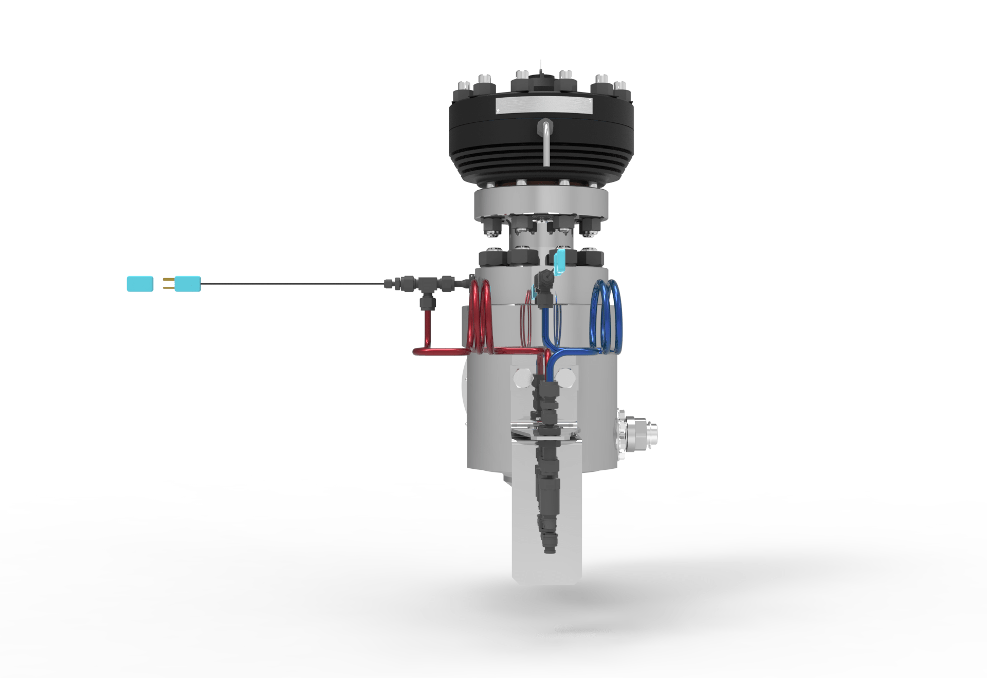
Now with reference to a hydraulic actuator 499 as shown in FIGS. 6-9, a sealing assembly 306, 307 provides a metal to metal seal to control fluid line. A piston collar 308 retains the seal assembly 306, 307 relative to the valve head stem 304. A piston member 309 is stationarily attached to the second ported housing 105 and locates a cylinder member 320. A metal to metal seal assembly is defined between the lowermost end 321 of the member 320 and the uppermost end 322 of cylindrical stop member 350 which, in turn, is secured at threads 323 to a cylindrical central housing member 324 which, in turn, is secured at threads to a lower closed end member 326.
The apparatus 100 will be run into the well W and positioned as shown in FIG. 1. When it is desired to open the control valve means 106, the apparatus 100 is first equalized by moving the equalizing valve head 303 from the equalizing valve seat member 302. This is effected by first applying an increase of pressure within the control fluid conduit through the passageway 301 to pressurize the interior of the cylinder below the lower dynamic wiper seal 327a to extend the cylinder away from the ported second housing 105. The cylinder stop 350 contacts the control mandrel 115 which moves the control mandrel 115 downwardly against the power spring 116 to compress such power spring 116. Now the shoulder 314c of the control mandrel 115 will move toward the shoulder 311a the distance of travel being the equalizing travel distance 305. As the shoulders 314c and the head 311a come together, the valve head 303 is stroked away from the seat member 302, thus permitting annulus fluid 401 to be equalized with pressure below the ported second housing 105. When the equalizing travel 305 is completed by continued application of fluid pressure through the control fluid passageway 301 from the control fluid line, the power spring 116 continues to be further compressed and one or more of the control valve means 106 are manipulated to open position with the valve head 108 being moved from the valve seat 107, respectively, depending upon the additional power defined through the control spring 112. Likewise, the control valve means 106 are manipulated to closed position by reduction in control fluid pressure through the control fluid conduit and the control fluid passageway 301, and the valve head means 106 are manipulated to closed position as the power in the spring 116 overcomes the fluid pressure in the control fluid passageway 301.
FIG. 3 is a view of the upper portion of annular safety valve 100 of the present invention in one-quarter longitudinal section view. Annular safety valve 100 includes ported second housing 105 which mates at threads 101 with production tubing A. The preferred annular safety valve 100 of the present invention includes two paths for receiving fluid. The first is a connector 509 which is adapted for coupling to a high pressure fluid hose which provides a control fluid to annular safety valve 100 of the present invention. Fluid directed from the control line of the high pressure hose is directed inward into annular safety valve 100 via fluid passage 301. The second opening is passageway 123, which will allow wellbore fluid in the annular region between tubing string 101 and casing C to pass through when valve 106 is in open condition.
FIGS. 11a and 11b show connector 509 and valve 106 in enlarged view. As shown in FIG. 11a, valve 106 includes valve head 108 which releasably engages valve seat 107. As shown, valve seat 107 is merely a circular passageway which is adapted in size and shape to sealingly engage a tapered portion of valve head 108. In the preferred embodiment of the present invention, valve head 108 and valve seat 107 are maintained in a normally-closed position, and cooperate in preventing the passage of fluid into annular safety valve 103, until a predetermined amount of pressure is applied by a high pressure hose to control port 301. As shown in FIG. 11b the uppermost extent of control port 301 is threaded or otherwise adapted to receive a control hose fitting 300. In the preferred embodiment of the present invention, other fluid passageways 123 and valve assemblies 106 are provided circumferentially around annular safety valve 100. Fluid passageways 123 which are not equipped with valve assemblies 106 may be plugged, as shown in FIG. 11c.
FIG. 10 is a cross-section view of annular safety valve 100 of the present invention in full cross-section view, as seen along lines A--A of FIG. 3. As shown, a plurality of valve assemblies 106 are provided, preferably three, each positioned 90 degrees apart. Also shown in FIG. 10 are fluoroplastic bearings 505 which receive guide members 507.
Returning now to FIG. 3, as shown, valve head 108 is biased upward relative to control mandrel 115 by spring 112, into normally-closed sealing engagement with valve seat 107. As shown, valve seat 107 is merely the end portion of ported second housing 105, which is equipped with a cylindrical fluid passage 123, and which is adapted in size and configuration to sealingly engage valve head 108a of valve member 108, when it is biased upward by spring 112. Valve head 108a is integrally formed with valve mandrel 111. Valve mandrel extends through the central region of spring 112, and is adapted to slidably engage a stationary piece 111a.
In the preferred embodiment of the present invention, high pressure fluid is directed from a high pressure fluid hose through fluid passage 301. The high pressure fluid operates to move a hydraulic actuator 499 between a normally-closed position and an open position, which serves to equalize the fluid pressure differential across annulus safety valve 100. In the preferred embodiment, as hydraulic actuator 499 is moved between a normally-closed position and an open position, control mandrel 115 (which extends circumferentially around inner conduit 102) is urged downward relative to inner conduit 102, causing valve assembly 106 to be moved from a normally-closed position and an open position, allowing annulus fluid to flow through the annulus safety valve 100.
The operation of hydraulic actuator 499 is graphically disclosed in FIGS. 6, 7, 8, and 9. FIGS. 6 and 7 together depict hydraulic actuator 499 in its normally-closed position. FIGS. 8 and 9 together depict hydraulic actuator 499 in an open position. The relative positions of hydraulic actuator 499 and valve assembly 106 is graphically disclosed in FIG. 12.
As shown in FIG. 4, movement of central mandrel 115 downward relative to inner conduit 102 causes compression of power spring 116. Therefore, as soon as high pressure fluid of a sufficient amplitude is no longer provided to fluid passage 301 to actuate hydraulic actuator 499, power spring 116 will urge control mandrel 115 upward relative to inner conduit 102, causing valve head 108a to engage valve seat 107, thus preventing the passage of fluid between annular safety valve 100 and fluid passageway 123.
FIG. 5 shows the lower end of annulus safety valve 100 of the present invention. As shown, annulus safety valve 100 is provided with external threads 122, which releasably engage a conventional wellbore packer assembly.
As shown in FIG. 6, piston lock nut 320 is secured in position relative to ported second housing 105 by threads 511. At its uppermost end, piston 309 includes piston stem 304, which is circumferentially engaged by piston collar 308 and seal assembly 306, 307. Piston lock nut 320 is provided exteriorly of piston 309. Piston lock nut 320 is in abutting relationship with cylindrical stop 350. Cylinder stop 350 and cylinder 324 are coupled together at threads 513. Annular region 515 is provided between stationary piston 309 and movable cylinder 324.
The discussion and exposition of hydraulic actuator 499 will continue with reference to FIG. 7. As shown, a number of components are provided in annular space 515 between stationary piston 309 and movable cylinder 324. These components include seal 325a, spring 325, and bearing 326. In addition, wiper seal 327 is provided in annular space 515 between stationary piston 309 and movable cylinder 324. Also provided in annular space 515 are support ferrule 328, lower wiper seal 327a, bearing 329, and wedge 330. All of the above components in annular space 515 are held in position by lock nut 331. These components do not interfere with the movement of piston 309 relative to movable cylinder 324.
At its lowermost end, stationary piston 309 terminates at seat 333, which engages plug stop seat 332, in a normally-closed mode of operation. The components disposed in annular space 515 between stationary piston 309 and movable cylinder 324 do not interfere with the movement of movable cylinder 324 relative to stationary piston 309. As high pressure fluid is directed downward within piston fluid channel 501 of stationary piston 309, force is exerted against plug stop seat 332.
Plug stop seat 332 is coupled to cylinder plug 326, and engages expander shim 334 at its lowermost end. Expander shim 334 engages spring 335. As fluid pressure is applied to the seat 333 of plug stop seat 332, plug stop seat 332 is urged downward relative to stationary piston 309, and causes expander shim 334 to compress spring 335. As seat 333 is brought out of contact with the lowermost end of stationary piston 309, fluid is allowed to enter the annular space 305 between cylinder 324 and piston 309. The pressure differential created across wiper seals 327, causes movable cylinder 324 to be urged downward relative to stationary piston 309, as shown more fully in FIGS. 8 and 9.
As shown in FIGS. 8 and 9, the preferred hydraulic actuation device 499 of the present invention is moved by high pressure fluid to an open position, with movable cylinder 324 moved downward relative to stationary piston 309. As shown in FIG. 8, cylinder stop 350 and piston lock nut 320 are separated by distance D1. This distance of travel is an amount sufficient to move valve head 108a a selected distance away from valve seat 107.
FIG. 12 is fragmentary longitudinal section view of annulus safety valve 100, which depicts the interrelationship between hydraulic actuator 499 and equalizing valve assembly 521. As movable cylinder 324 is moved downward, to the right, relative to stationary piston 309, in response to high pressure fluid directed downward through passage 301 to piston fluid channel 501, control mandrel 115 is likewise moved downward (to the right) along with movable cylinder 324. As discussed above, control mandrel 115 extends circumferentially around inner conduit 102, and thus will move valve head 303 out of sealing engagement with valve seat 302, causing equalizing valve 521 to be moved a selected distance 305 to allow equalization of pressure across annular safety valve 100. As shown in FIG. 12, equalizing valve 521 is similar in construction to valve members discussed above, and includes spring 525 which biases valve head 303 against valve seat 302. Valve head 303 is integrally formed and coupled with valve stem 311, which is movable downward relative to stationary guide pieces 527, 529, 531.
FIG. 13 is a fragmentary, longitudinal section view of the preferred annular safety valve 100 of the present invention, which depicts the relationship between valve assembly 106, and equalization valve assembly 521.
As shown in FIG. 13, when equalization valve assembly 521 is in an open condition, valve assembly 106 remains in its normally-closed condition, with valve head 108 sealingly engaging valve seat 107. The fluid path 551 which supplies fluid to equalizing valve assembly 521 is a tiny fluid path, much smaller in cross-sectional area than the fluid passage which provides fluid to valve assembly 106. The fluid path 551 of FIG. 13 allows for minute quantities of extremely high pressure fluid to be passed through annular safety valve 100 to equalize the pressure differential across annular safety valve 100 before valve head 108 is brought out of sealing engagement with valve seat 107. This is a safety feature which prevents catastrophic failure which frequently occurs when valves are open at high pressure differentials.
In broad terms, the present invention, valve assembly 106, hydraulic actuator 499, and equalizing valve assembly 521 cooperate together to allow the passage of fluid through annular safety valve 100. The process begins when hydraulic actuator 499 is actuated, so that movable cylinder 324 is displaced relative to stationary piston 309, in response to high pressure fluid directed into annular safety valve 100 by a high pressure hose (or control line). Movement of movable cylinder 324 relative to stationary piston 309 causes equalizing valve assembly 521 to move between a normally-closed position and an open position, to equalize pressure across annulus safety valve 100 prior to movement of valve assembly 106 between a normally-closed position and an open position. Valve assembly 106 is the final component in annular safety valve 100 which moves between closed and open positions.
In the preferred embodiment of the present invention, a plurality of valve assemblies 106 may be provided circumferentially about inner conduit 102, all mechanically coupled together by central mandrel 115, which extends circumferentially about inner conduit 102. Each of the plurality of valve assemblies 106 may be calibrated to open at a different fluid pressure level which is provided by a high pressure hose or control line, by fixing the length and position of valve mandrel 111 relative to control mandrel 115. For example, one valve assembly 106 may be adapted to open upon movement of movable cylinder 324 relative to stationary piston 309 by a selected distance D1. A second valve assembly 106 may be adapted to open at another, different distance D2 of travel of movable cylinder 324 relative to stationary piston 309. A third and final valve assembly 106 may be provided to move between closed and open positions upon movement of movable cylinder 324 relative to stationary piston 309 by a predetermined longer distance D3. As high pressure fluid is supplied to hydraulic actuator 499, it will move first to distance D1, then to distance D2, and finally to distance D3. Thus, the plurality of valve assemblies 106 may be sequentially and successively actuated at predetermined pressure thresholds. Of course, equalizing valve assembly 521 will actuate prior to any of valve assemblies 106 to equalize the high pressure differential across annular safety valve 100. In other embodiments, multiple equalizing valve assemblies 521 may be provided.
Finally, the present invention need not communicate with high pressure hoses or control lines. Instead, the annular region between the tubing and casing may be pressurized with a wellbore pump, or surface pump, to obtain sufficient pressure levels to operate hydraulic actuator 499, equalizing valve assembly 521, and one or more valve assemblies 106.
Tejas hydraulic wireline valves are typically used in multi-string wells, where there is a lack of annular space to accommodate Tubing Retrievable safety valves.
The Tejas SV-Regain™* is a wireline deployed, completion accessory tool designed for non-functioning tubing retrievable safety valves (TRSV’s). It will allow an operator to “regain” operational control of a non-functioning TRSV and resume production operations.
The RESTOR™ Series Wireline Retrievable Surface Controlled Subsurface Safety Valve (RESTOR) is designed by Tejas Research & Engineering to control production flow in oil and gas wells that use API standard weight tubing. The RESTOR is self-equalizing and uses a Tejas flapper closure system complete with a field proven through-the-flapper equalizing system and is both reliable and versatile. The RESTOR has been manufactured in compliance with API 14A and may be monogrammed upon request. Materials of construction are NACE approved and may be specified to any customer requirements. The RESTOR features a large, straight-through bore for minimum restriction and is certified for five year service life.
The Camco* type B-Series Wireline Retrievable Surface Controlled Subsurface Safety Valve is manufactured in compliance with API 14A and may be monogrammed upon request. Materials of construction are NACE approved and may be specified to any customer requirements. The B-Series WR-SCSSV features a large, straight-through bore for minimum restriction and a concentric piston actuation system for long-term, reliable performance.
The B-Series WRSV is offered in sizes 2.375 to 4.000 in. These valves are designed to accept any manufacturers’ locking mandrels and will set in any manufacturer hydraulic landing nipple or tubing retrievable safety valve when equipped with the appropriate locking mandrel and lock adapter. For recommendations on the best combination of B-Series safety system components to match a specific landing profile contact Tejas Research & Engineering or your local service provider.
A downhole safety valve refers to a component on an oil and gas well, which acts as a failsafe to prevent the uncontrolled release of reservoir fluids in the event of a worst-case-scenario surface disaster. It is almost always installed as a vital component on the completion.
These valves are commonly uni-directional flapper valves which open downwards such that the flow of wellbore fluids tries to push it shut, while pressure from the surface pushes it open. This means that when closed, it will isolate the reservoir fluids from the surface.
Most downhole safety valves are controlled hydraulically from the surface, meaning they are opened using a hydraulic connection linked directly to a well control panel. When hydraulic pressure is applied down a control line, the hydraulic pressure forces a sleeve within the valve to slide downwards. This movement compresses a large spring and pushes the flapper downwards to open the valve. When hydraulic pressure is removed, the spring pushes the sleeve back up and causes the flapper to shut. In this way, it is failsafe and will isolate the wellbore in the event of a loss of the wellhead. The full designation for a typical valve is "tubing retrievable, surface controlled, subsurface safety valve", abbreviated to TR-SCSSV.
The location of the downhole safety valve within the completion is a precisely determined parameter intended to optimise safety. There are arguments against it either being too high or too low in the well and so the final depth is a compromise of all factors. MMS regulations state that the valve must be placed no less than 30 m (100 ft) below the mudline.
The further down the well the DHSV is located, the greater the potential inventory of hydrocarbons above it when closed. This means that in the event of loss of containment at surface, there is more fluid to be spilled causing environmental damage, or in the worst case, more fuel for a fire. Therefore, placing the valve higher limits this hazard.
Another reason relates to the hydraulic control line. Hydraulic pressure is required to keep the valve open as part of the failsafe design. However, if the valve is too far down the well, then the weight of the hydraulic fluid alone may apply sufficient pressure to keep the valve open, even with the loss of surface pressurisation.
As part of the role of the DHSV to isolate the surface from wellbore fluids, it is necessary for the valve to be positioned away from the well where it could potentially come to harm. This implies that it must be placed subsurface in all circumstances, i.e. in offshore wells, not above the seabed. There is also the risk of cratering in the event of a catastrophic loss of the topside facility. The valve is specifically placed below the maximum depth where cratering is expected to be a risk.
If there is a risk of methane hydrate (clathrate) plugs forming as the pressure changes through the valve due to Joule–Thomson cooling, then this is a reason to keep it low, where the rock is warmer than an appropriately-calculated temperature.
Most downhole safety valves installed as part of the completion design are classed as "tubing retrievable". This means that they are installed as a component of the completion string and run in during completion. Retrieving the valve, should it malfunction, requires a workover. The full name for this most common type of downhole safety valve is a Tubing Retrievable Surface Controlled Sub-Surface Valve, shortened in completion diagrams to TRSCSSV.
If a tubing retrievable valve fails, rather than go to the expense of a workover, a "wireline retrievable" valve may be used instead. This type of valve can fit inside the production tubing and is deployed on wireline after the old valve has been straddled open.
The importance of DHSVs is undisputed. Graphic images of oil wells in Kuwait on fire after the First Gulf War after their wellheads were removed, demonstrate the perils of not using the components (at the time, they were deemed unnecessary because they were onshore wells). It is, however, not a direct legal requirement in many places. In the United Kingdom, no law mandates the use of DHSVs. However, the 1974 Health & Safety at Work Act requires that measures are taken to ensure that the uncontrolled release of wellbore fluids is prevented even in the worst case. The brilliance of the act is that it does not issue prescriptive guideline for how to achieve the goal of health and safety, but merely sets out the requirement that the goal be achieved. It is up to the oil companies to decide how to achieve it and DHSVs are an important component of that decision. As such, although not a legal requirement, it is company policy for many operators in the UKCS.
While the DHSV isolates the production tubing, a loss of integrity could allow wellbore fluid to bypass the valve and escape to surface through the annulus. For wells using gas lift, it may be a requirement to install a safety valve in the "A" annulus of the well to ensure that the surface is protected from a loss of annulus containment. However, these valves are not as common and they are not necessarily installed at the same position in the well, meaning it is possible that fluids could snake their way around the valves to surface.

A well completion including a submersible pump is disclosed in the aforementioned related application and includes a safety valve which is hydraulically controlled from the surface for shutting off flow of oil up the tubing string and gas into the tubing string-casing annulus in the event of any emergency which affects the hydraulic pressure in the control system.
The three valves housed in the retreivable safety valve all operate on longitudinal movement of a long concentric tube in the valve, resulting in slow valve closing or opening because of greater mass of the tube and greater friction drag on the long tube.
In accordance with this invention there is provided a short retreivable well safety valve having a tubular housing with separate longitudinal central and annular flow passages, a first valve in the central flow passage and a second valve in the annular flow passage coupled to the first valve.
The well safety valve is run into a tubing string to land in cooperating nipples above a well packer, which is above a submersible pump, for controlling flow from the pump through the central flow passage to surface and flow of gas through the packer to the annular flow passage of the safety valve and into the tubing-casing annulus above the packer.
Closure of the safety valve shuts off flow in both the central and annular flow passages of the well valve and if the pump continues to operate directs gas and pumped fluid flow from below the packer through recirculating passages back into the well bore below the packer.
Another object of this invention is to provide an improved safety valve wherein the retrievable portion is very short and low weight for economy and ease of installation, operation and retrieval.
Another object of the invention is to provide safety valve for use with a pump in an oil and gas well to permit continuous operation of the pump when the well is shut-in.
It is another object of the invention to provide a well safety valve of the character described which permits a well pump to recirculate well fluids in a well below a closed safety valve.
It is another object of the invention to provide a well safety valve for use with submersible well pump which shuts off the flow of well fluids to the surface under emergency conditions directing the well fluids along flow paths permitting the pump to operate continuously recirculating the well fluids back to the well bore below the packer.
It is another object of the invention to provide a well safety valve which controls the flow of well fluids along both a central bore and a separate annular flow passage around the central bore for conducting pumped liquids along the central bore and gas along the annular flow passage.
Another object of this invention is to provide a safety valve wherein separation of central bore and annular flow passage flow is maintained while the valve is open by the central bore valve engaging a lower seat.
FIG. 1 is a schematic of a well completion employing a well safety valve embodying the features of the invention and showing the safety valve open and the well producing.
Referring now to FIG. 1 showing a producing well 10 in which oil is pumped through tubing and gas flows to surface in the tubing casing annulus. The well bore 11 is lined with casing 12 provided with perforations 13 through which liquid and gas may flow into the casing from an earth formation. A tubing string 14 is suspended from wellhead 15 and connected to a suitable packer 16 which seals with casing 12. A lower section of tubing 14A is connected to and suspended from the lower end of the packer supporting a pump 17 connected to the lower end of the lower tubing section. An electric cable 18 extending from the wellhead through the packer to the pump conducts electric power to the pump. A retreivable safety valve 19 for shutting off flow up the tubing string and annulus from the producing formation is supported in the tubing string above the packer from a locking mandrel 20 which releasably locks the safety valve in a landing nipple section 21 of the tubing string. A hydraulic control line 22 connects the tubing landing nipple section with surface control manifold 23 to remotely control the operation of the safety valve.
The retrievable safety valve 19 of this invention includes a fail safe ball valve assembly 24 operated by control fluid in line 22 for controlling the flow of pumped oil up the tubing string, an annulus bypass valve 25, controlling the flow of gas through annular passage 26 around the ball valve, which is formed on locking the safety valve in cooperating tubing nipples and lower end seals 27 for sealing to the inside of the tubing. Gas collecting below the packer flows thru the packer to surface up annular passage 28 around the power cable, thru cross-over port 29, up annulus 26 and through open valve 25, into annulus 26A to exit through ports 52 and 30 into the tubing casing annulus 31.
When the safety valve 19 is open for well production as shown in FIG. 1, the ball valve 24 is open and oil pumped from the producing formation up the tubing through the packer and safety valve to surface. The annulus bypass valve 25 is open and gas flow from casing annulus below the packer is directed through the packer and safety valve flow passages to ports 30 and into the casing annulus above the packer.
When the safety valve is closed shutting off well production as illustrated by FIG. 2, the ball valve is closed, the annulus bypass valve is closed and recirculating flow passage circuit for oil and gas is formed below the closed ball valve so the pump may continue to run and recirculate oil and gas.
Formation oil and gas for recirculation is taken into the pump and pumped up the tubing 14A and discharged through ports 32 into annulus 26, to flow through port 29 and down annulus 28 into the annulus 31 below the packer and back to the pump intake for further circulation. It is not necessary to turn off the pump when the well is shut-in by the safety valve, as the pump may continue to run and freely recirculate oil and gas through the recirculating circuit.
Structural details of the invention valve 19 are shown in FIGS. 2A-2D and include assemblies and parts which when landed in cooperating tubing nipples form a central longitudinal flow passage for pumped oil controlled by ball valve 24 and a separate annular flow passage for gas controlled by bypass valve 25. A central operator tube is movable longitudinally within the safety valve for operating both the bypass and ball valves.
Referring to FIG. 2, the safety valve body includes a top sub 33, which has an internally threaded upper end portion 34 for connecting the valve body to the lower end of a conventional lock mandrel 20, and houses a resilient seal 35, for slidably sealing to operating piston 36. The top sub has port 37 for control fluid and is sealingly threaded to the housing 39 at thread 38. Resilient seal 40 is housed on the operating piston to slidably seal the operating piston in the housing and form sealed variable volume chamber C. The lower end of the housing is threadedly connected to spring housing 41 with thread 42 and sealed thereto with resilient seal 43. Retained between the lower end of the housing and an external shoulder 44 on the spring housing is a seal assembly 45 to seal between the inner tubing wall and the safety valve body when the safety valve is in operating position in the tubing. Attached to the lower end of the operating piston, at thread 46, is an operating tube 47, sealed to the piston with resilient seal 48, and connecting the piston to the ball and annular valves. Disposed around the operator tube and in the spring housing bore 49 is a closing spring 50. A ported connector 51 provided with ports 52, which align with exhaust ports 30, (FIG. 1) is connected to the lower end of the spring housing with sealing thread 53. Internal annular flow passage 26A is formed by and around a lower reduced outside diameter section of the operating tube. A retainer ring 54 abuts shoulder 55 on the operating tube positioning the closing spring between the upper end of the ported connector and ring, biasing the operating tube upwardly to close the annular and ball valves.
Control fluid introduced into chamber C through port 37 from line 22 moves the piston and operating tube downwardly, compressing spring 50, opening and holding the annular and ball valves open. Attached to the lower end of the ported connector with sealed threads 56 is a connector mandrel 57 carrying a second seal assembly 45, which is positioned between the lower end of the ported connector and shoulder 58 on the mandrel and seals with the inner tubing wall below ports 52 to direct gas flow from ports 52 thru ports 30 into the annulus 31 above the packer. A tapered internal seating surface 59 is provided on the lower end of the connector mandrel engageable with a tapered external valve surface 60 on the upper end of the upper valve seat 61, to which operating tube 47 is connected at threads 62 which are sealed by resilient seal 63.
The annulus bypass and ball valves are housed in a cylindrical valve housing 64 which is connected to the lower end of the connector mandrel 57 by threads 65. Provided through the walls of the valve housing are flow ports 66 and recirculation flow ports 32. On the lower end of upper seat 61 is internal annular spherical seating surface 67 to which spherical seal surface on outside ball valve member 68 is held engaged by pins 69 on control arms 70 fitted into flat bottom holes 71 in parallel flats 72 on opposite sides of the ball member and shoulders 73 on the control arms abutting shoulder 74 of groove 75 around the upper seat. The ball member is provided with a bore 68A. Attached to the inside of the valve housing are offset pins 76 (see FIG. 3) which engage valve ball slots 77 to rotate the ball on longitudinal movement of the piston, operating tube, upper seat and control arms.
Threadedly connected to the lower end of the valve housing by threads 78 is lower seat 79 having an outwardly tapering internal seat 80 on its upper end, which is sealingly engaged by the valve ball when control fluid piston pressure has moved the annular and ball valves down to their open positions, to prevent commingling of fluid flow through the ball valve with gas flow through passages 26 and 26A and flow through ports 32. Connected to the lower end of the lower seat with threads 81, which are sealed with resilient seal 82, is tube 83, which positons seal assembly 27 below port 29 to seal with the inner tubing wall. On the lower end of the tube connected with thread 84 and sealed with seal 85 is a seal mandrel 86 carrying the seal assembly, which is retained on the mandrel by guide 87. The guide is connected to the mandrel with threads 88.
A well completed to utilize the invention safety valve is shown in FIG. 1 wherein the invention safety valve has been installed to control flow of liquids pumped up the tubing to surface and gas flow from the tubing casing annulus below the packer to the tubing casing annulus above the packer and further to surface.
After forming perforations 13 through the well casing 12, the pump 17 with cable 18, connecting tubing 14A, packer 16, connecting tubing 14 with nipple section 21 and control line 22 are lowered into the well until the packer has reached the proper depth and has been set. The invention safety valve is installed in the tubing nipple section by connecting to conventional locking mandrel 20 and lowering on wireline from surface to releasably lock the locking mandrel in a nipple.
The locked mandrel supports the safety valve and positions upper seal assembly 45 to seal in tubing above ports 30 and lower seal assembly 27 to seal below port 29. The seal assembly 20A on the locking mandrel and upper seal assembly 45 on the valve body form an annulus around the valve body in the tubing directing control fluid from line 22 into port 37 to control the safety valve hydraulically. Upper seal assembly 45 and lower seal assembly 45 form an annulus around the valve body directing gas flow from ports 52 through ports 30 into tubing c


 8613371530291