
annular safety valve factory
Annulus control safety valves from Baker Hughes prevent uncontrolled flow in your well’s annular space to ensure that your gas-lift operations run smoothly and safely.
You maintain downhole safety with non-elastomeric technology and a rod piston for long-term sealing durability that withstands high pressures and temperatures. Single control lines actuate the valve while a loss-of-control pressure line provides emergency closure.
Optimize production at lower operating costs. Maximize your well productivity with annulus valves designed with a large annular flow area that minimizes pressure drops
Reduce risk. Ensure safe and reliable operation with annulus safety valves configured to your operating conditions and proven in stringent prototype testing prior to deployment

Wells with planned or unplanned sustained annulus pressure (SAP) pose a considerable risk to personnel and facilities. In these situations, annulus line gate valves (a gasket, bonnet seal or stem seal) are the primary well barrier envelope elements, with no back up in case of failure.
Most O&G companies follow a double barrier well integrity management policy. In wells operated with SAP the single barrier gate valves are in breach of this policy. Annulus line gate valves also significantly increase the ‘footprint’ of the wellhead. They require regular testing, maintenance and occasional replacement, resulting in significant life cycle costs.
The Hydraulic Surface Annulus Safety (HSASTM) valve addresses all of the challenges listed above. It is installed in the wellhead VR profile, where (in wells with SAP) it becomes an independently testable element of the primary barrier envelope.

Surface-controlled subsurface safety valves (SCSSVs) are critical components of well completions, preventing uncontrolled flow in the case of catastrophic damage to wellhead equipment. Fail-safe closure must be certain to ensure proper security of the well. However, this is not the only function in which it must be reliable—the valve must remain open to produce the well. Schlumberger surface controlled subsurface safety valves exceed all ISO 10432 and API Spec 14A requirements for pressure integrity, leakage acceptance criteria, and slam closure.
Through decades of innovation and experience, Schlumberger safety valve flapper systems are proven robust and reliable. The multizone dynamic seal technology for hydraulic actuation of subsurface safety valves is a further improvement in reliability performance when compared with traditional seal systems in the industry.
The multizone seal technology is currently available in the GeoGuard high-performance deepwater safety valves, which is validated to API Spec 14A V1 and V1-H.

Halliburton provides proven, high-performance tubing-retrievable and wireline-retrievable subsurface safety valves (SSSV) designed to reliably shut-in (fail safe) if a catastrophic event occurs, allowing operators to maintain safe operations.

The Halliburton NE™ tubing-retrievable safety valve (TRSV) is a single rod-piston non-elastomer flapper valve designed for general production with enhanced reliability and long life. The valve includes the non-elastomer hydraulic actuator design from the highly reliable SP™ line of safety valves. Along with the metal-to-metal (MTM) body joints and closure mechanism, the actuator places this valve in the premium category while keeping costs economical. The simple, compact design enhances the valve’s overall reliability and provides for trouble-free operation.

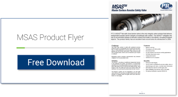
PTC’s HSASTMand MSASTMfail-safe close wellhead annulus barrier valves are the only integrity-valve solutions that delivers independent double barrier integrity. The HSASTMmitigates the risk of uncontrolled release of annular content from leaks or accidents.

The tubing-retrievable subsurface safety valve (SSSV) provides well protection against pressure drop and system failure in wireline and thru-tubing operations. This retrievable safety valve is controlled from the surface with a hydraulic control line. The valve connects to the tubing string and remains open if adequate pressure is maintained. If pressure drops below the threshold (as occurs in the beginning stages of losing well control), the valve closes. This creates a barrier in the tubing to prevent fluids from rushing up the tubing.
The Flow Component Testing Facilities (FCTF) at SwRI are accredited through the American Petroleum Institute (API) to perform validation testing on both surface and subsurface safety valves. The facilities are also used to perform safety valve testing on other downhole safety valves, riser isolation valves, and wellhead valves. All testing is completed under an API Q1 and ISO 17025 quality management system.
SwRI performs SSSV testing on surface control safety valves (SCSSV) and subsurface control safety valves (SSCSV), subsurface injection safety valves (SSISV), and annular safety valves.Validation Testing – Annex B
SwRI performs testing on various types of valves used as underwater safety valves (USV), surface safety valves (SSV), and boarding shutdown valves (BDSV). This equipment is essential for emergency shutdown of offshore production.

SSSV: Subsurface Safety Valve: a valve installed in the tubing down the well to prevent uncontrolled flow in case of an emergency through the tubing when actuated. These valves can be installed by wireline or as an integral part of the tubing. Subsurface Valves are usually divided into the following categories.
SCSSV: Surface-Controlled Subsurface Safety Valves: SSSV which is controlled from the surface and installed by wireline or as an integral part of the tubing.
SSCSV (storm choke): Subsurface-Controlled Subsurface Safety Valve: SSSV which is actuated by the flow characteristics of the well, and is wireline retrievable.
ASV: Annulus Safety Valve: a valve installed in the well to prevent uncontrolled flow in the casing-tubing annulus when actuated. It consists of an annular safety valve packer with a by-pass. The opening in the by-pass is controlled by a safety valve, which can be an integral part of the packer on a wireline retrievable valve.
The tubing safety valve is installed to provide a flow barrier in the production tubing string, between the tail pipe and the surface or mudline. Such a valve consists of 3 main items:
Safety valve should not be considered as an extra barrier in the tubing when the well is closed-in for a long period of time. Sealing is not optimal because of design space limitations. They should not be used to regularly shut-in the well.
The annulus safety valve (ASV) provides a flow barrier in the casing-tubing annulus. It consists of an annular safety valve packer with a by-pass. The opening of the by-pass is controlled by a safety valve, which can be an integral part of the packer or a wireline retrievable valve. It is a surface controlled, fail-safe closed device for annular flow.
In general, the ASV is installed in gas lifted wells where the annulus is filled with compressed gas and serves as a barrier. Because of gas lift valves, the tubing cannot be considered as a barrier between the reservoir and the surface. Although the gas lift valves are commonly equipped with check valves, they are not a valid barrier. The ASV is normally located at a shallow depth to reduce the volume of the gas stored in the annulus between the ASV and the wellhead.
The valve body and connections should be at least as strong as the tubing. It should provide leak resistance to internal and external pressures and be compatible with the fluids.
During the installation of the tubing string, it is necessary to keep the valve open. This can be done by inserting a retrievable lock-open tool in the valve, without or in combination with the control signal from surface.
Multiple zone completions, where wireline jobs are frequent on equipment installed beneath the safety valve. The larger bore of a TR-SSSV facilitates the operations, where a WR-SSSV normally has to be retrieved.
The wireline retrievable safety valve (WR SCSSV) is run on wireline. A lock mandrel is screwed on top of the WR SCSSV that enables using a landing nipple. This nipple must hold the valve/mandrel assembly against pressure differentials loads. The nipple has a polished bores to seal the path between WR SCSSV and landing nipple by seals fitted to the outside of the valve/mandrel assembly.
With hydraulically operated WR SCSSVs, the external seals have also the function of containing the control fluid that is to be transmitted to the valve actuator.
The landing nipple for an electrically operated valve has a connection for an electric control line and an inductive coupler to transmit the signal to the WR SCSSV.
Trough Flowline retrievable safety valves use specially constructed mandrels and landing nipples. They must have a stronger hold-open force than SCSSVs, because the Trough Flowline tools are circulated upwards in the tubing string, which tends to drag the valve"s flow tube up, causing the valve to close. To overcome this problem the actuator hold-open force should be higher than the sum of the normal hold open force and the drag forces that can be experienced. Trough Flowline retrievable SSSVs can be used for subsea completions where wireline operations are difficult.
Another application is to install a SSSV in tubing without a landing nipple. Such a system consists of a production packer with an integral safety valve. The assembly is positioned by the coiled tubing and the packer is set by pressure from the coiled tubing.
Subsurface controlled valves are normally open and are designed to close with an abnormal change in well condition. They detect the flow or well pressure and close when the set limit is reached. Basically there are three different concepts:
Surface controlled valves utilise valve elements that are normally closed. This fail-safe mode requires that the valve is to be opened by a hydraulic control-line pressure. Loss of this pressure will result in the closing of the valve by a spring. The hydraulic pressure is supplied from a surface control panel to the valve and acts on the actuator. Typical for hydraulic operated SCSSVs is the hydrostatic head pressure, generated by the vertical column of control fluid, which additionally acts on the valve actuator.
the surface control line pressure and the time for valve operation will give an indication whether the valve opening and closing performance is satisfactory;
TR-SCSSVs of which the hydraulic actuator is damaged can be put back into function by inserting a back-up valve (insert valve), which can be operated with the existing hydraulic control system;
Electrically operated SCSSVs have in common with hydraulic SCSSVs that the differential pressure over the closed valve must be equalised before the valve can be opened and a means to keep the valve open must be permanently available from surface for fail safe operation.
With electric valves that means is an electrical signal, either dc or ac. Loss of this signal will result in closing of the valve. The force to close is always provided by expanding steel springs, which are precompressed by either electric power or by the well pressure.
One type of mechanically operated SSSV is the Go-Devil valve from Otis. This safety valve is a normally open valve. It is designed to close by an impact force on the head of the valve, provided by a heavy ball that is dropped from a ball-dropper assembly at surface. The impact force will activate the spring based mechanical linkage, that moves the valve to the closed position.
The ball-dropper assembly is flange mounted on top of the Christmas tree. The pocket of the ball dropper retains the ball, sized to activate the Go-Devil SSSV by falling against flow and impacting the head of the valve. The ball dropper assembly retains the ball until the loss of the control signal activates the release mechanism.
Three types of valve closure elements are commonly used for SSSV: the ball, the flapper and the poppet type. The flapper valve can further be divided in flat, contoured and curved flappers, while the poppet valve can be divided into closed body and sleeve type poppet valves. All types of closure elements pinch off the fluid stream by a pair of opposing surfaces rather than sliding surfaces. This principal method has the advantage that it can provide a good tight shut-off when the sealing surfaces are sound.
As noted the flapper valves may be flat, curved or contoured. The latter two were introduced to obtain a better OD/ID ratio, as they are shaped to fit when in the open position, more efficiently in the annular space of the valve housing.
The seat angle is the shape of the flapper sealing surfaces, which is an important parameter of the valve sealing performance. Traditional flapper valves have a seat angle of 45°, as the angled seat has the advantage that:
Due to the characteristics of the curved flapper design the seat angle may vary from 0° to 60° along the flapper circumference, thus requiring stringent alignment of the sealing faces. The contoured flapper design has an angled sealing surface over the full circumference of the flapper and thus has potential to provide good sealing. Field experience indicate that the flapper valve type is more reliable than the ball valve type.
When a SSSV is closed, a high differential pressure may be present across the valve closure element. Opening the valve under this condition will be difficult, if not impossible, because of the incapability of the relatively small valve mechanism to cope with the load working on the large diameter closure element. Insufficient equalising will introduce high loads that could deform critical valve parts. Also, erosive wash-out on the closure element by the sudden rush of well fluid through the partly opened valve can occur. Therefore, prior to opening a SSSV it is necessary to equalise the differential pressure.
The depth at which to set the subsurface safety valve depends upon a number of variables, such as hydrate and wax formation tendencies, deviation kick-off depth, scale precipitation, earthquake probabilities, etc. The OD of the safety valve may influence the casing/tubing string configuration and should be addressed at the conceptual design stage.
For tubing safety valves it is obvious that the deeper the valve is set (closer to the hydrocarbon source) the more protection it will give to the completion. However, the application of a deep-set tubing SSSV generates some unfavourable conditions, namely:
the higher temperature further downhole effects the reliability and the longevity of non-metal valve parts, for instance polymeric seals in hydraulic valves and electric/electronic parts in electric valves;
the hydrostatic head pressure generated by the hydraulic control-line column will generate excessive forces on the valve operating mechanism. Hence, designing and manufacturing of these valves becomes more complicated.
Furthermore, the required control pressure to operate a single control line valve (the majority of SSSVs) could become too high and more than the pressure rating of standard well completion equipment.
The approach for determining the required hydraulic control pressure at surface to hold a valve open depends on the type of valve, viz. the single control line valve, the dual control line valve and the valve with a pressure chamber.
Due to friction in the valve mechanism and the spring characteristic, there is a certain spread between the valve opening pressure (Pvo) and closing pressure (Pvc).
To ensure that the valve is completely open, a safety factor or pressure margin (Pm) is added to the surface control pressure. Hence, the available control pressure at surface to open the valve must be at least:
The dual control line valve or the pressure balanced valve uses a second control line from surface to balance the generated hydrostatic head pressure in the control line. The forces acting to operate this type of valve are as follows:
Due to friction in the valve mechanism and the spring characteristic, there is a certain spread between the valve opening pressure (Pvo) and closing pressure (Pvc).
When the valve is in the fully open position and the control and the balance line are both filled with fluid of the same fluid gradient, the following force equilibrium exists:
To insure that the valve is completely open, a safety factor or pressure margin (Pm) is added to the surface control pressure. Hence, the available control pressure at surface to open the valve must be at least:
The dome charged valve uses a pressure in an integral dome to (partly) balance the generated hydrostatic head pressure in the control line. The forces acting to operate this type of valve are as follows:
Due to friction in the valve mechanism and the spring characteristic, there is a certain spread between the valve opening pressure (Pvo) and closing pressure (Pvc).
To ensure that the valve is completely open, a safety factor or pressure margin (Pm) is added to the surface control pressure. Hence, the available control pressure at surface to open the valve must be at least:
The theoretical maximum setting depth of a single control line SSSV depends on the capacity of the valve closing spring to overcome the generated hydrostatic head pressure in the control line. For fail safety it is essential that the tubing pressure is not taken into account for the assistance of valve closing, even though single control line valves are assisted by this pressure. Hence, the governing factors for the maximum valve setting depth are:
* For fail safety, the worst case must be assumed, one in which the control line ruptures near the valve and annulus fluid will enter the control line. Therefore, for any completion the heaviest fluid gradient, either from the control fluid or from the annulus fluid, is used as the minimum control line fluid gradient.
Because the hydrostatic head pressure in the control line is counteracted, the setting depths of the dual control-line and the dome-charged valves are theoretically not limited.

Introduction to Safety Valves . . . . . . . . . . . . . . . . . . . . . . . . . . . . . . . . . . . . . . . . . . . . . . . . . . . . . . . . . . . . . . . . . . 6
Annular Model WA(E)-5 . . . . . . . . . . . . . . . . . . . . . . . . . . . . . . . . . . . . . . . . . . . . . . . . . . . . . . . . . . . . . . . . . . . . 39

A downhole safety valve refers to a component on an oil and gas well, which acts as a failsafe to prevent the uncontrolled release of reservoir fluids in the event of a worst-case-scenario surface disaster. It is almost always installed as a vital component on the completion.
These valves are commonly uni-directional flapper valves which open downwards such that the flow of wellbore fluids tries to push it shut, while pressure from the surface pushes it open. This means that when closed, it will isolate the reservoir fluids from the surface.
Most downhole safety valves are controlled hydraulically from the surface, meaning they are opened using a hydraulic connection linked directly to a well control panel. When hydraulic pressure is applied down a control line, the hydraulic pressure forces a sleeve within the valve to slide downwards. This movement compresses a large spring and pushes the flapper downwards to open the valve. When hydraulic pressure is removed, the spring pushes the sleeve back up and causes the flapper to shut. In this way, it is failsafe and will isolate the wellbore in the event of a loss of the wellhead. The full designation for a typical valve is "tubing retrievable, surface controlled, subsurface safety valve", abbreviated to TR-SCSSV.
The location of the downhole safety valve within the completion is a precisely determined parameter intended to optimise safety. There are arguments against it either being too high or too low in the well and so the final depth is a compromise of all factors. MMS regulations state that the valve must be placed no less than 30 m (100 ft) below the mudline.
The further down the well the DHSV is located, the greater the potential inventory of hydrocarbons above it when closed. This means that in the event of loss of containment at surface, there is more fluid to be spilled causing environmental damage, or in the worst case, more fuel for a fire. Therefore, placing the valve higher limits this hazard.
Another reason relates to the hydraulic control line. Hydraulic pressure is required to keep the valve open as part of the failsafe design. However, if the valve is too far down the well, then the weight of the hydraulic fluid alone may apply sufficient pressure to keep the valve open, even with the loss of surface pressurisation.
As part of the role of the DHSV to isolate the surface from wellbore fluids, it is necessary for the valve to be positioned away from the well where it could potentially come to harm. This implies that it must be placed subsurface in all circumstances, i.e. in offshore wells, not above the seabed. There is also the risk of cratering in the event of a catastrophic loss of the topside facility. The valve is specifically placed below the maximum depth where cratering is expected to be a risk.
If there is a risk of methane hydrate (clathrate) plugs forming as the pressure changes through the valve due to Joule–Thomson cooling, then this is a reason to keep it low, where the rock is warmer than an appropriately-calculated temperature.
Most downhole safety valves installed as part of the completion design are classed as "tubing retrievable". This means that they are installed as a component of the completion string and run in during completion. Retrieving the valve, should it malfunction, requires a workover. The full name for this most common type of downhole safety valve is a Tubing Retrievable Surface Controlled Sub-Surface Valve, shortened in completion diagrams to TRSCSSV.
If a tubing retrievable valve fails, rather than go to the expense of a workover, a "wireline retrievable" valve may be used instead. This type of valve can fit inside the production tubing and is deployed on wireline after the old valve has been straddled open.
The importance of DHSVs is undisputed. Graphic images of oil wells in Kuwait on fire after the First Gulf War after their wellheads were removed, demonstrate the perils of not using the components (at the time, they were deemed unnecessary because they were onshore wells). It is, however, not a direct legal requirement in many places. In the United Kingdom, no law mandates the use of DHSVs. However, the 1974 Health & Safety at Work Act requires that measures are taken to ensure that the uncontrolled release of wellbore fluids is prevented even in the worst case. The brilliance of the act is that it does not issue prescriptive guideline for how to achieve the goal of health and safety, but merely sets out the requirement that the goal be achieved. It is up to the oil companies to decide how to achieve it and DHSVs are an important component of that decision. As such, although not a legal requirement, it is company policy for many operators in the UKCS.
While the DHSV isolates the production tubing, a loss of integrity could allow wellbore fluid to bypass the valve and escape to surface through the annulus. For wells using gas lift, it may be a requirement to install a safety valve in the "A" annulus of the well to ensure that the surface is protected from a loss of annulus containment. However, these valves are not as common and they are not necessarily installed at the same position in the well, meaning it is possible that fluids could snake their way around the valves to surface.
This application claims the benefit of U.S. Provisional Application No. 62/773640, filed on Nov. 30, 2018, entitled Annular Safety Valve with Groove Around Port, the contents of which is hereby incorporated in its entirety by this reference.
The present disclosure relates generally to an annular safety valve (ASV) that can be positioned downhole within a wellbore, and more particularly (although not necessarily exclusively), to an ASV that includes a groove positioned around a port or an opening of the ASV.
Certain aspects and features of the present disclosure relate to an ASV that can be positioned in the wellbore. The ASV may be a part of a completion string that is positionable downhole in a wellbore. The ASV can actuate between an open and a closed position. The ASV can include a housing having one or more openings for gas injection. The ASV can further include a poppet positioned within the opening. A surface region of the poppet can close or seal against a seat of the opening in the closed position. The ASV can be actuated to the closed position in response to an emergency situation to shut in injected gas pressure in the annulus of the wellbore for safety reasons. In the closed position, the ASV traps the injection gas pressure in the annulus below the ASV. In the open position, the poppet may not close or seal the opening such that under normal gas injection conditions, the ASV allows gas injection via the annulus to move past the ASV. The position of the poppets of the ASV can be controlled via an actuator within the ASV that may move the poppet (or a set of poppets) off a seat (i.e. move the poppet sealing-face off the seat of the housing) surrounding the opening to position the ASV in the open position. The actuator may be coupled to a control line. The actuator may also move the poppet (or a set of poppets) onto the seat to position the ASV in the closed position. To close the ASV, the control line pressure can be bled off and pressure from a spring can push the poppet(s) (i.e. the poppet sealing-face) back onto the seat, moving the ASV to the closed position and trapping annulus pressure below the ASV. With the ASV in the closed position and pressure trapped below the poppets, the housing can subjected to tubing pressure and axial loading on the poppets.
FIG. 1 is a schematic illustration of a well system 10 having a wellbore assembly according to one aspect of the present disclosure. The well system 10 includes a borehole that is a wellbore 12 extending through a surface 14 and various earth strata. The well system 10 may be a land based well system or a sea based well system. A casing string 13 may be positioned within the wellbore 12, and a tubing string 15 may be positioned within the casing string 13. The tubing string 15 may be for example a completion string. The tubing string 15 may include an ASV 16. The ASV 16 may provide a communication path in an annular area between the tubing string 15 and the casing string 13. The ASV 16 may have an open position to allow pressure to transmit between a first annular area 18 of the wellbore 12 (e.g. annular area between the casing string 13 and the tubing string 15) below the ASV 16 and a second annular area 20 of the wellbore (e.g. annular area between the casing string 13 and the tubing string 15) above the ASV 16. The ASV 16 may have a closed position to prevent pressure to transmit between the first annular area 18 of the wellbore 12 below the ASV 16 and the second annular area 20 of the wellbore 12 above the ASV 16.
As described above with respect to FIG. 2, the grooves 112, 124 can separate a portion of the seats 110, 122 from the other portions of the housing 200. The separation between the seat 110, 122and other portions of the housing 105 can allow the housing 105 to deform into the groove 112, 124 in response to pressure, without affecting the shape or size of the openings 104, 120, or the seats 110, 122. For example, the grooves 112, 124 can isolate a sealing face of the seats 110, 122that contacts and seals against a poppet (not shown) from the influence of the remainder of the housing 105 expanding due to internal tubing pressure or annular pressure below the ASV 100. Thus, the grooves 112, 124 can provide a certain amount of flexibility to the respective seats 110, 122 and allow the portions of the respective seats 110, 122 that seal against the poppets to retain their shapes. The sealing between the poppets and the respective seats 110, 122 can be improved and gas leakage between the poppets and the respective seats 110, 122 when the ASV 100 is in a closed position can be reduced by providing the grooves 112, 124.
Example 1 is an annular safety valve positionable in a wellbore, the annular safety valve comprising: a housing having an opening extending through the housing to allow to allow pressure to transmit between a first annular area of the wellbore below the annular safety valve and a second annular area of the wellbore above the annular safety valve, wherein the housing defines the opening by a seat face; a poppet extending through the opening; and a groove at least partially surrounding the seat face for maintaining a shape of the seat face in response to an increase in pressure in the first annular area of the wellbore, wherein the shape of the seat face corresponds to a surface of the poppet for preventing pressure from transmitting between the first annular area of the wellbore and the second annular area of the wellbore when the annular safety valve is in a closed position.
Example 2 is the annular safety valve of example(s) 1, further comprising: a second opening, wherein the housing defines the second opening by a second seat face; a second poppet extending through the second opening; and a second groove at least partially surrounding the second seat face for maintaining a shape of the second seat face in response to an increase in pressure in the first annular area of the wellbore, wherein the shape of the second seat face corresponds to a surface of the second poppet for preventing pressure from transmitting between the first annular area of the wellbore and the second annular area of the wellbore when the annular safety valve is in the closed position.
Example 5 is the annular safety valve of example(s) 1-4, further comprising at least two additional openings, each opening of the two additional openings is associated with a respective groove at least partially surrounding each of the at least two additional openings.
Example 6 is the annular safety valve of example(s) 1-5, further comprising a seat insert positioned within opening, the seat insert having a seat face for maintaining a shape of the seat face in response to an increase in pressure in the first annular area of the wellbore, wherein the shape of the seat face corresponds to a surface of the poppet for preventing pressure from transmitting between the first annular area of the wellbore and the second annular area of the wellbore when the annular safety valve is in a closed position in response to an increase in pressure in the first annular area of the wellbore.
Example 7 is an annular safety valve positionable in a wellbore, the annular safety valve comprising: a housing having an opening extending through the housing to allow pressure to transmit between a first annular area of the wellbore below the annular safety valve and a second annular area of the wellbore above the annular safety valve; and a poppet extending through the opening; at least one of (a) a seat insert positioned within opening, the seat insert having a sealing surface for maintaining a shape of the sealing surface in response to an increase in pressure in the first annular area of the wellbore, wherein the shape of the sealing surface corresponds to a surface of the poppet for preventing pressure from transmitting between the first annular area of the wellbore and the second annular area of the wellbore when the annular safety valve is in a closed position in response to an increase in pressure in the first annular area of the wellbore, or (b) a groove at least partially surrounding the opening for maintaining a shape of the seat face in response to an increase in pressure in the first annular area of the wellbore, wherein the shape of the seat face corresponds to a surface of the poppet for preventing pressure from transmitting between the first annular area of the wellbore and the second annular area of the wellbore when the annular safety valve is in a closed position.
Example 8 is the annular safety valve of example(s) 7, further comprising: a second opening in the housing; a second poppet extending through the second opening; and a second seat insert positioned within second opening, the second seat insert having a second sealing surface for maintaining a shape of the second seat face in response to an increase in pressure in the first annular area of the wellbore, wherein the shape of the second sealing surface corresponds to a surface of the second poppet for preventing pressure from transmitting between the first annular area of the wellbore and the second annular area of the wellbore when the annular safety valve is in the closed position.
Example 9 is the annular safety valve of example(s) 7-8, further comprising at least two additional openings, each opening of the two additional openings is associated with a respective seat insert extending within each opening of the at least two additional openings.
Example 10 is the annular safety valve of example(s) 7-8, wherein the housing comprises a first material and wherein the seat insert comprises the first material.
Example 11 is the annular safety valve of example(s) 7-10, wherein the housing comprises a first material and wherein the seat insert comprises a second material that is different from the first material.
Example 15 is the annular safety valve of example(s) 7-14, wherein the sealing surface of the seat insert has a concave shape and wherein the surface of the poppet has a convex shape.
Example 16 is the annular safety valve of example(s) 7-15, further comprising a groove at least partially surrounding the opening for aiding in maintaining the shape of the sealing surface in response to an increase in pressure in the first annular area of the wellbore.
Example 17 is a downhole assembly positionable within a casing string of a wellbore comprising: a completion string including an annular safety valve, wherein the annular safety valve further comprises: a housing having a plurality of openings extending through the housing to allow to allow pressure to transmit between a first annular area of the wellbore below the annular safety valve and a second annular area of the wellbore above the annular safety valve, a plurality of seat faces, each seat face of the plurality of seat faces defining an opening of the plurality of openings; a plurality of poppets, each poppet of the plurality of poppets extending through a respective opening of the plurality of openings, wherein each poppet of the plurality of poppets has a surface that corresponds to a surface of each respective seat face for preventing pressure from transmitting between the first annular area of the wellbore and the second annular area of the wellbore when the annular safety valve is in a closed position; and a plurality of grooves, each groove of the plurality of grooves extending at least partially around a respective seat face of the plurality of seat faces for maintaining a shape of the respective seat face in response to an increase in pressure in the first annular area of the wellbore.

Following closely on the heels of our first VR toolkit rental order in Oman, Petroleum Technology Company (PTC) has now received its first Purchase Order for Master Surface Annulus Safety ( MSAS)Valves from an Oman based OPCO.
The MSAS Valves are installed in cases where either planned or unplanned annulus pressure exists. They uniquely facilitate a double barrier against the escape of the annulus contents, at the interface between the wellhead and the annulus line valve, while also facilitating bi-directional flow to or from the well annulus.
This is an appeal by the plaintiff in a suit in equity to recover for the infringement of two letters patent, from a decree dismissing the bill. The suit was brought in the Circuit Court of the United States for the Northern District of Illinois by the Consolidated Safety Valve Company, a Connecticut corporation, against Erastus B. Kunkle, on letters patent No. 58,294, granted to George W. Richardson, September 25, 1866, for an improvement in safety valves, and on other letters patent, No. 85,963, granted to the same person, January 19, 1869, for an improvement in safety valves for steam boilers or generators. These are the same two patents which were the subject matter of the litigation involved in the case of Consolidated Safety Valve Company v. Crosby Steam Gauge & Valve Company, decided by this Court at October Term, 1884, and
"A safety valve, with the circular or annular flange or lip c c, constructed in the manner or substantially in the manner shown, so as to operate as and for the purpose herein described,"
"a valve in which are combined an initial area, an additional area, a huddling chamber beneath the additional area, and a strictured orifice leading from the huddling chamber to the open air, the orifice being proportioned to the strength of the spring, as directed."
"the combination of the surface beyond the seat of the safety valve, with the means herein described for regulating or adjusting the area of the passage for the escape of steam, substantially as and for the purpose described,"
The decree in the present case was made in January, 1883, and proceeded, as it states, on the ground that the defendant"s valves did not infringe the patents. This also appears from the decision of the circuit court, reported in 14 F. 732. As the defendant"s valves have no huddling chamber, and no strictured orifice leading from a huddling chamber to the open air, we are of opinion that they do not infringe either of the patents.
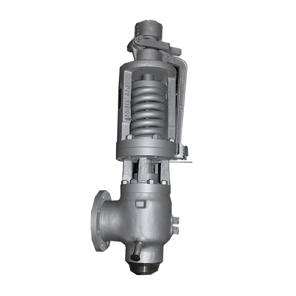
Safety valve Model 64Safety valve 90º angular type of rapid opening (pop action), full nozzle, and spring loaded, adjusting ring, conventional or balanced.Safety valve Model 55Safety valve 90º angular type of rapid opening, semi nozzle, spring loaded.Safety valve Model 51Safety valve 90º angular type of rapid opening (pop action), full nozzle, and spring loaded, adjusting ring, conventional or balanced.Safety valve Model 3-50Safety valve 90º angular type of rapid opening (pop action), full nozzle, spring loaded, adjusting ring.Emergency Valve 2000Safety device intended for installation on storage tanks with the finality of assure a quick evacuation of large volume of fluid inside the tank in the event of an overpressure due to fire condition.Breather Valve 3400Breather valve for overpressure and vacuum, with flanged and threaded connections. This valve is categorized in three different types: Breather, Vacuum and Breather/Vacuum combined.Pilot Operated Safety Relief ValvePilot operated pressure relief valve able to operate at considerably higher set pressure than with spring loaded safety relief valves, the valve operation and lift are unaffected by back-pressure.Valve silencersNoise in some safety and control valves generates levels above 150 dBA / dBC, a situation that is a concern for the technical operations and maintenance of plants.Represented brandsWe work together with major brands adding value to our solutions and services.


 8613371530291