
annular safety valve in stock

Annulus control safety valves from Baker Hughes prevent uncontrolled flow in your well’s annular space to ensure that your gas-lift operations run smoothly and safely.
You maintain downhole safety with non-elastomeric technology and a rod piston for long-term sealing durability that withstands high pressures and temperatures. Single control lines actuate the valve while a loss-of-control pressure line provides emergency closure.
Optimize production at lower operating costs. Maximize your well productivity with annulus valves designed with a large annular flow area that minimizes pressure drops
Reduce risk. Ensure safe and reliable operation with annulus safety valves configured to your operating conditions and proven in stringent prototype testing prior to deployment
Wells with planned or unplanned sustained annulus pressure (SAP) pose a considerable risk to personnel and facilities. In these situations, annulus line gate valves (a gasket, bonnet seal or stem seal) are the primary well barrier envelope elements, with no back up in case of failure.
Most O&G companies follow a double barrier well integrity management policy. In wells operated with SAP the single barrier gate valves are in breach of this policy. Annulus line gate valves also significantly increase the ‘footprint’ of the wellhead. They require regular testing, maintenance and occasional replacement, resulting in significant life cycle costs.
The Hydraulic Surface Annulus Safety (HSASTM) valve addresses all of the challenges listed above. It is installed in the wellhead VR profile, where (in wells with SAP) it becomes an independently testable element of the primary barrier envelope.
Surface-controlled subsurface safety valves (SCSSVs) are critical components of well completions, preventing uncontrolled flow in the case of catastrophic damage to wellhead equipment. Fail-safe closure must be certain to ensure proper security of the well. However, this is not the only function in which it must be reliable—the valve must remain open to produce the well. Schlumberger surface controlled subsurface safety valves exceed all ISO 10432 and API Spec 14A requirements for pressure integrity, leakage acceptance criteria, and slam closure.
Through decades of innovation and experience, Schlumberger safety valve flapper systems are proven robust and reliable. The multizone dynamic seal technology for hydraulic actuation of subsurface safety valves is a further improvement in reliability performance when compared with traditional seal systems in the industry.
The multizone seal technology is currently available in the GeoGuard high-performance deepwater safety valves, which is validated to API Spec 14A V1 and V1-H.

The Annulus Pressure Relief System (also known as the B-Annulus Relief System) was developed from TCO"s Chemical Injection System product line. The product is approved as an ISO 14998 V0 barrier, and features check valves and an internal integrated filtration system.

The purpose of down hole safety systems is to protect personnel, the environment and the surface facilities from threats to safety caused by the hydrocarbons produced from the reservoir.
This concept is well established and field proven equipment and procedures are available. However, procedures are available. However, the majority of the effort in analysing, designing, testing and implementation of ever more performance down hole safety devices, performance down hole safety devices, has mainly been orientated towards tubing valves. Down hole safety devices are mainly dedicated to the tubing, ie SC-SSV"s acting as a back up of the safety equipment installed on Christmas-Trees.
Due to these communications, the tubing cannot be considered as a barrier between hydrocarbon in the reservoir and surface surroundings. Although the orifices or G-L valves are generally equipped with check valves preventing the tubing content to flow back in the annulus, it is our opinion that this equipment should not be regarded as a valid barrier.
Operators must be confident in reliability of these mission critical components. Tejas designs and tests their API-14A Safety Valves to the most stringent standards.
Camco* Products & Services built the first eValve under license from the original inventors in the mid 1970s. There have been 12 or more installations of this valve design in wells over the years, deployed by Camco. At that point in its history Camco was the world leader in the hydraulic SCSSV market and subsequently made a business decision not to pursue further development of the eValve believing it was consuming its own market. Deep set SCSSV applications at that time were non-existent. As a result, assignment and ownership of eValve returned to the original inventor/licensors. With recent renewed industry interest in electric SCSSVs for deep set applications, the owners of the eValve contacted Tejas about bringing it up to current industry standards.
The Tejas tubing retrievable injection valve, or TRIV™, is a subsurface controlled, injection safety valve that features the patent-pending Tejas VOi™ variable orifice insert. It is designed to prevent injection fluid from flowing back out of the well if the surface control system becomes damaged or malfunctions. The TRIV also provides pressure management as the surrounding reservoir wells are produced.
The Tejas HPHT Tubing Retrievable Surface Controlled Subsurface Safety Valve (SCSSV) is a 25,000 psi rated working pressure, non-equalizing, xHPHT safety valve. It is designed to minimize the loss of reservoir fluids or production equipment by shutting in the well in the event a catastrophic surface or subsurface event were to occur.
The patent-pending Tejas TRIS™ is a dual barrier tubing retrievable injection sleeve system featuring the VOi™ variable orifice choke and is designed for multi-zone injection. The TRIS™ is similar to conventional sliding sleeves that have an inner sleeve shifted open to establish communication/injection from the tubing to the annulus/formation. Unlike conventional sliding sleeves which are shifted mechanically (via wireline or coiled tubing shifting tools) the TRIS™ is shifted open with differential pressure from flow alone. When injection is suspended, the TRIS™ and VOi™ return to the closed position, providing dual barrier protection, one from below the VOi™ and the second from the annular space behind the TRIS™.
The Tejas TRCF series surface controlled subsurface safety valves (SCSSV) are rated to 10,000 psi [68,948 kPa] working pressure at 350deg F [176.7degC]. TRCF valves are designed to automatically shut in the well and prevent unrestricted well flow in the event of a catastrophic surface or subsurface event.
This valve is a rod piston actuated, normally closed, fail-safe safety valve which is held open with control pressure supplied from the surface by an emergency shut-down (ESD) system to a hydraulic control line that connects to the valve. Loss of control line, ESD system, pressure returns the valve to the closed postion.
The Tejas TRSV is a 5,000 psi rated working pressure, safety valve with a self-equalizing option. It is a rod piston actuated, normally spring closed, fail safe, safety valve which is held open with independent control pressure supplied from the surface by a hydraulic control line that extends through the wellhead to an emergency shut-down (ESD) system at the surface. Removing the control line pressure will return the valve to its normally closed position.
PTC’s HSASTMand MSASTMfail-safe close wellhead annulus barrier valves are the only integrity-valve solutions that delivers independent double barrier integrity. The HSASTMmitigates the risk of uncontrolled release of annular content from leaks or accidents.

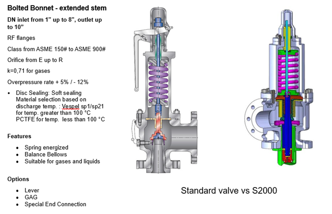
The valve operates on a hydraulic piston principle. To open, hydraulic pressure slightly higher than the well pressure is applied to move the piston downward. This pressure unseats the secondary seat, allowing pressure to enter through equalizing ports. Then, as additional hydraulic pressure is applied to the piston, it continues downward movement, pushing the flapper open.

Safety valves are designed to automatically shut in the flow of a well in the event surface controls fail or surface equipment becomes damaged. They are classified according to the location from which they are controlled – surface or subsurface. In this article, subsurface safety valve types, operating systems, working principle, setting depth, and selection process are presented.
It is advisable, and in most cases mandatory, to have a secondary means of closure for all wells capable of natural flow to the surface. The installation on of a sub-surface safety valve (SSSV) will provide this emergency closure capability.
Operating systems may be either remotely operated on a fail-safe principle from surface (SCSSV) actuated from a control panel located on surface, or will be a subsurface controlled (SSCSV), designed to close automatically when a predetermined flow condition occurs in the well (actuated by the pressure differential/flow velocity across the valve).
In case of SCSSV, a 1/4″ inch stainless steel control line is attached to the outside of the tubing string and installed when the tubing is installed. Depending on the wellhead pressure, it may be necessary to keep as much as 4000 to 5000 psi on the control line to keep the valve open.
The differential type subsurface controlled subsurface safety valve senses pressure drop across a flow bean. There are several variations of the differential type SSCSV. Although they employ different sealing devices, such as a flapper or ball, they all are controlled with a flow bean and spring tension.
As shown in the following video, when hydraulic pressure is applied down a control line, the hydraulic pressure forces a sleeve within the valve to slide downwards. This movement compresses a large spring and pushes the flapper (in case of flapper type SCSSV) or the ball (in case of ball type SCSSV) downwards to open the valve. When hydraulic pressure is removed, the spring pushes the sleeve back up and causes the flapper (or the ball) to shut. In this way, it is failsafe and will isolate the wellbore in the event of a loss of the wellhead.
The location of the downhole safety valve within the completion is a precisely determined parameter intended to optimise safety. There are arguments against it either being too high or too low in the well and so the final depth is a compromise of all factors. MMS regulations state that the valve must be placed no less than 100′ below the mudline.
Following closely on the heels of our first VR toolkit rental order in Oman, Petroleum Technology Company (PTC) has now received its first Purchase Order for Master Surface Annulus Safety ( MSAS)Valves from an Oman based OPCO.
The MSAS Valves are installed in cases where either planned or unplanned annulus pressure exists. They uniquely facilitate a double barrier against the escape of the annulus contents, at the interface between the wellhead and the annulus line valve, while also facilitating bi-directional flow to or from the well annulus.

Introduction to Safety Valves . . . . . . . . . . . . . . . . . . . . . . . . . . . . . . . . . . . . . . . . . . . . . . . . . . . . . . . . . . . . . . . . . . 6
Annular Model WA(E)-5 . . . . . . . . . . . . . . . . . . . . . . . . . . . . . . . . . . . . . . . . . . . . . . . . . . . . . . . . . . . . . . . . . . . . 39
A downhole safety valve refers to a component on an oil and gas well, which acts as a failsafe to prevent the uncontrolled release of reservoir fluids in the event of a worst-case-scenario surface disaster. It is almost always installed as a vital component on the completion.
These valves are commonly uni-directional flapper valves which open downwards such that the flow of wellbore fluids tries to push it shut, while pressure from the surface pushes it open. This means that when closed, it will isolate the reservoir fluids from the surface.
Most downhole safety valves are controlled hydraulically from the surface, meaning they are opened using a hydraulic connection linked directly to a well control panel. When hydraulic pressure is applied down a control line, the hydraulic pressure forces a sleeve within the valve to slide downwards. This movement compresses a large spring and pushes the flapper downwards to open the valve. When hydraulic pressure is removed, the spring pushes the sleeve back up and causes the flapper to shut. In this way, it is failsafe and will isolate the wellbore in the event of a loss of the wellhead. The full designation for a typical valve is "tubing retrievable, surface controlled, subsurface safety valve", abbreviated to TR-SCSSV.
The location of the downhole safety valve within the completion is a precisely determined parameter intended to optimise safety. There are arguments against it either being too high or too low in the well and so the final depth is a compromise of all factors. MMS regulations state that the valve must be placed no less than 30 m (100 ft) below the mudline.
The further down the well the DHSV is located, the greater the potential inventory of hydrocarbons above it when closed. This means that in the event of loss of containment at surface, there is more fluid to be spilled causing environmental damage, or in the worst case, more fuel for a fire. Therefore, placing the valve higher limits this hazard.
Another reason relates to the hydraulic control line. Hydraulic pressure is required to keep the valve open as part of the failsafe design. However, if the valve is too far down the well, then the weight of the hydraulic fluid alone may apply sufficient pressure to keep the valve open, even with the loss of surface pressurisation.
As part of the role of the DHSV to isolate the surface from wellbore fluids, it is necessary for the valve to be positioned away from the well where it could potentially come to harm. This implies that it must be placed subsurface in all circumstances, i.e. in offshore wells, not above the seabed. There is also the risk of cratering in the event of a catastrophic loss of the topside facility. The valve is specifically placed below the maximum depth where cratering is expected to be a risk.
If there is a risk of methane hydrate (clathrate) plugs forming as the pressure changes through the valve due to Joule–Thomson cooling, then this is a reason to keep it low, where the rock is warmer than an appropriately-calculated temperature.
Most downhole safety valves installed as part of the completion design are classed as "tubing retrievable". This means that they are installed as a component of the completion string and run in during completion. Retrieving the valve, should it malfunction, requires a workover. The full name for this most common type of downhole safety valve is a Tubing Retrievable Surface Controlled Sub-Surface Valve, shortened in completion diagrams to TRSCSSV.
If a tubing retrievable valve fails, rather than go to the expense of a workover, a "wireline retrievable" valve may be used instead. This type of valve can fit inside the production tubing and is deployed on wireline after the old valve has been straddled open.
The importance of DHSVs is undisputed. Graphic images of oil wells in Kuwait on fire after the First Gulf War after their wellheads were removed, demonstrate the perils of not using the components (at the time, they were deemed unnecessary because they were onshore wells). It is, however, not a direct legal requirement in many places. In the United Kingdom, no law mandates the use of DHSVs. However, the 1974 Health & Safety at Work Act requires that measures are taken to ensure that the uncontrolled release of wellbore fluids is prevented even in the worst case. The brilliance of the act is that it does not issue prescriptive guideline for how to achieve the goal of health and safety, but merely sets out the requirement that the goal be achieved. It is up to the oil companies to decide how to achieve it and DHSVs are an important component of that decision. As such, although not a legal requirement, it is company policy for many operators in the UKCS.
While the DHSV isolates the production tubing, a loss of integrity could allow wellbore fluid to bypass the valve and escape to surface through the annulus. For wells using gas lift, it may be a requirement to install a safety valve in the "A" annulus of the well to ensure that the surface is protected from a loss of annulus containment. However, these valves are not as common and they are not necessarily installed at the same position in the well, meaning it is possible that fluids could snake their way around the valves to surface.
Of all the challenges you face keeping your customers’ plants operating at full capacity, safety and relief valves shouldn’t be one of them. NASVI’s job is to give you the confidence that your valve supply chain is rock solid regardless the pressure it’s under.


 8613371530291