
annular safety valve quotation
The purpose of down hole safety systems is to protect personnel, the environment and the surface facilities from threats to safety caused by the hydrocarbons produced from the reservoir.
This concept is well established and field proven equipment and procedures are available. However, procedures are available. However, the majority of the effort in analysing, designing, testing and implementation of ever more performance down hole safety devices, performance down hole safety devices, has mainly been orientated towards tubing valves. Down hole safety devices are mainly dedicated to the tubing, ie SC-SSV"s acting as a back up of the safety equipment installed on Christmas-Trees.
Due to these communications, the tubing cannot be considered as a barrier between hydrocarbon in the reservoir and surface surroundings. Although the orifices or G-L valves are generally equipped with check valves preventing the tubing content to flow back in the annulus, it is our opinion that this equipment should not be regarded as a valid barrier.

This application claims the benefit of U.S. Provisional Application No. 62/773640, filed on Nov. 30, 2018, entitled Annular Safety Valve with Groove Around Port, the contents of which is hereby incorporated in its entirety by this reference.
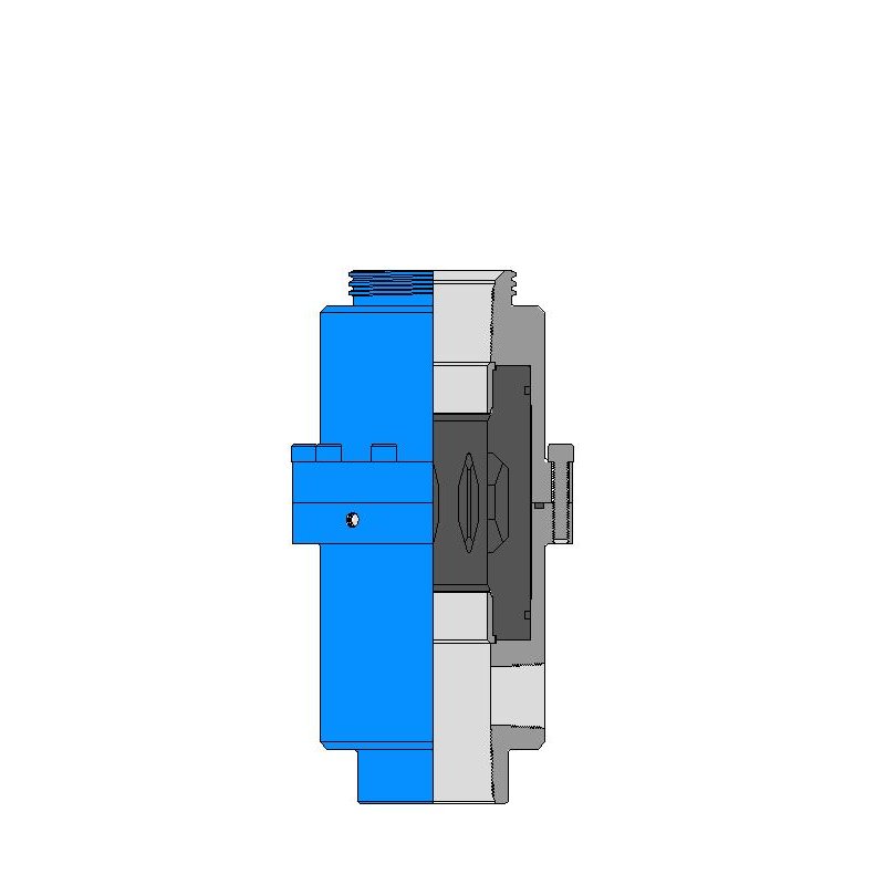
The present disclosure relates generally to an annular safety valve (ASV) that can be positioned downhole within a wellbore, and more particularly (although not necessarily exclusively), to an ASV that includes a groove positioned around a port or an opening of the ASV.
Certain aspects and features of the present disclosure relate to an ASV that can be positioned in the wellbore. The ASV may be a part of a completion string that is positionable downhole in a wellbore. The ASV can actuate between an open and a closed position. The ASV can include a housing having one or more openings for gas injection. The ASV can further include a poppet positioned within the opening. A surface region of the poppet can close or seal against a seat of the opening in the closed position. The ASV can be actuated to the closed position in response to an emergency situation to shut in injected gas pressure in the annulus of the wellbore for safety reasons. In the closed position, the ASV traps the injection gas pressure in the annulus below the ASV. In the open position, the poppet may not close or seal the opening such that under normal gas injection conditions, the ASV allows gas injection via the annulus to move past the ASV. The position of the poppets of the ASV can be controlled via an actuator within the ASV that may move the poppet (or a set of poppets) off a seat (i.e. move the poppet sealing-face off the seat of the housing) surrounding the opening to position the ASV in the open position. The actuator may be coupled to a control line. The actuator may also move the poppet (or a set of poppets) onto the seat to position the ASV in the closed position. To close the ASV, the control line pressure can be bled off and pressure from a spring can push the poppet(s) (i.e. the poppet sealing-face) back onto the seat, moving the ASV to the closed position and trapping annulus pressure below the ASV. With the ASV in the closed position and pressure trapped below the poppets, the housing can subjected to tubing pressure and axial loading on the poppets.
FIG. 1 is a schematic illustration of a well system 10 having a wellbore assembly according to one aspect of the present disclosure. The well system 10 includes a borehole that is a wellbore 12 extending through a surface 14 and various earth strata. The well system 10 may be a land based well system or a sea based well system. A casing string 13 may be positioned within the wellbore 12, and a tubing string 15 may be positioned within the casing string 13. The tubing string 15 may be for example a completion string. The tubing string 15 may include an ASV 16. The ASV 16 may provide a communication path in an annular area between the tubing string 15 and the casing string 13. The ASV 16 may have an open position to allow pressure to transmit between a first annular area 18 of the wellbore 12 (e.g. annular area between the casing string 13 and the tubing string 15) below the ASV 16 and a second annular area 20 of the wellbore (e.g. annular area between the casing string 13 and the tubing string 15) above the ASV 16. The ASV 16 may have a closed position to prevent pressure to transmit between the first annular area 18 of the wellbore 12 below the ASV 16 and the second annular area 20 of the wellbore 12 above the ASV 16.
As described above with respect to FIG. 2, the grooves 112, 124 can separate a portion of the seats 110, 122 from the other portions of the housing 200. The separation between the seat 110, 122and other portions of the housing 105 can allow the housing 105 to deform into the groove 112, 124 in response to pressure, without affecting the shape or size of the openings 104, 120, or the seats 110, 122. For example, the grooves 112, 124 can isolate a sealing face of the seats 110, 122that contacts and seals against a poppet (not shown) from the influence of the remainder of the housing 105 expanding due to internal tubing pressure or annular pressure below the ASV 100. Thus, the grooves 112, 124 can provide a certain amount of flexibility to the respective seats 110, 122 and allow the portions of the respective seats 110, 122 that seal against the poppets to retain their shapes. The sealing between the poppets and the respective seats 110, 122 can be improved and gas leakage between the poppets and the respective seats 110, 122 when the ASV 100 is in a closed position can be reduced by providing the grooves 112, 124.
Example 1 is an annular safety valve positionable in a wellbore, the annular safety valve comprising: a housing having an opening extending through the housing to allow to allow pressure to transmit between a first annular area of the wellbore below the annular safety valve and a second annular area of the wellbore above the annular safety valve, wherein the housing defines the opening by a seat face; a poppet extending through the opening; and a groove at least partially surrounding the seat face for maintaining a shape of the seat face in response to an increase in pressure in the first annular area of the wellbore, wherein the shape of the seat face corresponds to a surface of the poppet for preventing pressure from transmitting between the first annular area of the wellbore and the second annular area of the wellbore when the annular safety valve is in a closed position.
Example 2 is the annular safety valve of example(s) 1, further comprising: a second opening, wherein the housing defines the second opening by a second seat face; a second poppet extending through the second opening; and a second groove at least partially surrounding the second seat face for maintaining a shape of the second seat face in response to an increase in pressure in the first annular area of the wellbore, wherein the shape of the second seat face corresponds to a surface of the second poppet for preventing pressure from transmitting between the first annular area of the wellbore and the second annular area of the wellbore when the annular safety valve is in the closed position.
Example 5 is the annular safety valve of example(s) 1-4, further comprising at least two additional openings, each opening of the two additional openings is associated with a respective groove at least partially surrounding each of the at least two additional openings.
Example 6 is the annular safety valve of example(s) 1-5, further comprising a seat insert positioned within opening, the seat insert having a seat face for maintaining a shape of the seat face in response to an increase in pressure in the first annular area of the wellbore, wherein the shape of the seat face corresponds to a surface of the poppet for preventing pressure from transmitting between the first annular area of the wellbore and the second annular area of the wellbore when the annular safety valve is in a closed position in response to an increase in pressure in the first annular area of the wellbore.
Example 7 is an annular safety valve positionable in a wellbore, the annular safety valve comprising: a housing having an opening extending through the housing to allow pressure to transmit between a first annular area of the wellbore below the annular safety valve and a second annular area of the wellbore above the annular safety valve; and a poppet extending through the opening; at least one of (a) a seat insert positioned within opening, the seat insert having a sealing surface for maintaining a shape of the sealing surface in response to an increase in pressure in the first annular area of the wellbore, wherein the shape of the sealing surface corresponds to a surface of the poppet for preventing pressure from transmitting between the first annular area of the wellbore and the second annular area of the wellbore when the annular safety valve is in a closed position in response to an increase in pressure in the first annular area of the wellbore, or (b) a groove at least partially surrounding the opening for maintaining a shape of the seat face in response to an increase in pressure in the first annular area of the wellbore, wherein the shape of the seat face corresponds to a surface of the poppet for preventing pressure from transmitting between the first annular area of the wellbore and the second annular area of the wellbore when the annular safety valve is in a closed position.
Example 8 is the annular safety valve of example(s) 7, further comprising: a second opening in the housing; a second poppet extending through the second opening; and a second seat insert positioned within second opening, the second seat insert having a second sealing surface for maintaining a shape of the second seat face in response to an increase in pressure in the first annular area of the wellbore, wherein the shape of the second sealing surface corresponds to a surface of the second poppet for preventing pressure from transmitting between the first annular area of the wellbore and the second annular area of the wellbore when the annular safety valve is in the closed position.
Example 9 is the annular safety valve of example(s) 7-8, further comprising at least two additional openings, each opening of the two additional openings is associated with a respective seat insert extending within each opening of the at least two additional openings.
Example 10 is the annular safety valve of example(s) 7-8, wherein the housing comprises a first material and wherein the seat insert comprises the first material.
Example 11 is the annular safety valve of example(s) 7-10, wherein the housing comprises a first material and wherein the seat insert comprises a second material that is different from the first material.
Example 15 is the annular safety valve of example(s) 7-14, wherein the sealing surface of the seat insert has a concave shape and wherein the surface of the poppet has a convex shape.
Example 16 is the annular safety valve of example(s) 7-15, further comprising a groove at least partially surrounding the opening for aiding in maintaining the shape of the sealing surface in response to an increase in pressure in the first annular area of the wellbore.
Example 17 is a downhole assembly positionable within a casing string of a wellbore comprising: a completion string including an annular safety valve, wherein the annular safety valve further comprises: a housing having a plurality of openings extending through the housing to allow to allow pressure to transmit between a first annular area of the wellbore below the annular safety valve and a second annular area of the wellbore above the annular safety valve, a plurality of seat faces, each seat face of the plurality of seat faces defining an opening of the plurality of openings; a plurality of poppets, each poppet of the plurality of poppets extending through a respective opening of the plurality of openings, wherein each poppet of the plurality of poppets has a surface that corresponds to a surface of each respective seat face for preventing pressure from transmitting between the first annular area of the wellbore and the second annular area of the wellbore when the annular safety valve is in a closed position; and a plurality of grooves, each groove of the plurality of grooves extending at least partially around a respective seat face of the plurality of seat faces for maintaining a shape of the respective seat face in response to an increase in pressure in the first annular area of the wellbore.
Annulus control safety valves from Baker Hughes prevent uncontrolled flow in your well’s annular space to ensure that your gas-lift operations run smoothly and safely.
You maintain downhole safety with non-elastomeric technology and a rod piston for long-term sealing durability that withstands high pressures and temperatures. Single control lines actuate the valve while a loss-of-control pressure line provides emergency closure.
Optimize production at lower operating costs. Maximize your well productivity with annulus valves designed with a large annular flow area that minimizes pressure drops
Reduce risk. Ensure safe and reliable operation with annulus safety valves configured to your operating conditions and proven in stringent prototype testing prior to deployment

The WellStar® tubing-retrievable safety valve is a general production, hydraulically operated, downhole TRSV. The rugged hydraulic actuator of the WellStar safety valve provides durability and isolates the internal workings from well fluids through its unique construction. The metal-to-metal (MTM) sealing integrity in the body joints and closure mechanism places it in a premium valve category while featuring an economical price. Proven through years of installations, the simple, compact design enhances the valve’s overall reliability and provides for trouble-free operation.

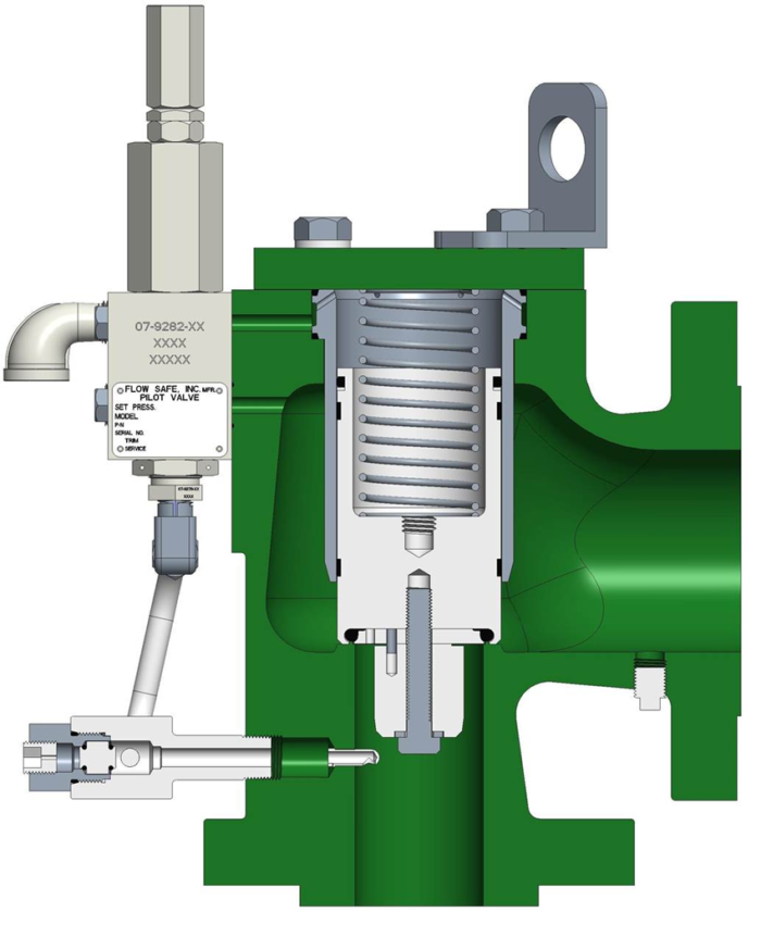
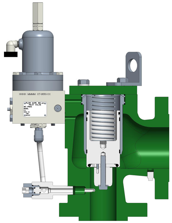
The F7000/F8000 series POSRV’s features the first direct mount pilot valve with integral porting. Design provides for easy conversion of orifice sizes through addition of annular flow plug (F8000 series), interchangeable pilot mounting (F100/F200/F300/F500), and field adjustability. Other features include a low profiles, inline repair, and minimal connections.
Please note that these relief valves are only designed to handle normal thermal stresses. Further consideration must be made to account for other pressure increase incidents including surges and fires.

"A safety valve with the circular or annular flange or lip c c, constructed in the manner, or substantially in the manner, shown, so as to operate as and for the purpose herein described,"
the patentee is entitled to cover a valve in which are combined an initial area, an additional area, a huddling chamber beneath the additional area, and a strictured orifice leading from the huddling chamber to the open air, the orifice being proportioned to the strength of the spring, as directed.
Richardson was the first person who made a safety valve which, while it automatically relieved the pressure of steam in the boiler, did not, in effecting
His valve was the first which had the strictured orifice to retard the escape of the steam and enable the valve to open with increasing power against the spring and close suddenly, with small loss of pressure in the boiler.
The direction given in the patent that the flange or lip is to be separated from the valve seat by about one sixty-fourth of an inch for an ordinary spring, with less space for a strong spring and more space for a weak spring, to regulate the escape of steam as required, is a sufficient description as matter of law, and it is not shown to be insufficient as a matter of fact.
Letters patent No. 85,963, granted to said Richardson January 19, 1869, for an improvement in safety valves for steam boilers or generators, are valid.
"The combination of the surface beyond the seat of the safety valve, with the means herein described for regulating or adjusting the area of the passage for the escape of steam, substantially as and for the purpose described,"
The patents of Richardson are infringed by a valve which produces the same effects in operation by the means described in Richardson"s claims, although the valve proper is an annulus and the extended surface is a disc inside of the annulus, the Richardson valve proper being a disc and the extended surface an annulus surrounding the disc, and although the valve proper has two ground joints, and only the steam which passes through one of them goes through the stricture, while, in the Richardson valve, all the steam which passes into the air goes through the stricture, and although the huddling chamber is at the center instead of the circumference, and is in the seat of the valve, under the head, instead of in the head, and the stricture is at the circumference of the seat of the valve instead of being at the circumference of the head.
The fact that the prior patented valves were not used and the speedy and extensive adoption of Richardson"s valve support the conclusion as to the novelty of the latter.
On the 27th of May, 1879, the Consolidated Safety valve Company, a Connecticut corporation, brought a suit in equity in the Circuit Court of the United States for the District of Massachusetts against the Crosby Steam Gage and Valve Company, a Massachusetts corporation, for the infringement of letters patent No. 58,294, granted to George W. Richardson September 25, 1866, for an improvement in steam safety valves. The specification of the patent is as follows:
"Be it known that I, George W. Richardson, of the City of Troy, in the County of Renesselaer, in the State of New York, have invented a new and useful improvement on a safety valve for steam generators, and I do hereby declare that the following is a full, clear, and exact description of the construction and operation of the same, reference being had to the annexed drawings, making a part of this specification, in which Fig. 1 is an end view of my improved safety valve and its seat, as seen from the bottom; Fig. 2 is an end view of the valve alone, as seen from the bottom; Fig. 3 is a vertical section at x x, Fig. 1, of the valve and seat in position; Fig. 4 is a vertical section at y y, Fig. 2, of the valve alone. Similar colors and letters of reference indicate corresponding parts in the several figures. A A, is the head of the safety valve; B B B B are wings to guide the valve into its seat E E; c c is a circular or annular flange or lip, extending over, slightly below, and fitting loosely around the outer edge of the valve seat E E; D D is a circular or annular chamber into which the steam immediately passes when the valve lifts from its seat at the ground joint F F; E E is the valve seat; F F is the ground joint of the valve and seat; P is the countersink or center upon which the point of the stud extending from the scale lever rests in the usual manner. The nature of my invention consists in increasing the area of the head of the common safety valve outside of its ground joint and terminating it in such a way as to form an increased resisting surface against which the steam escaping
from the generator shall act with additional force after it has lifted the valve from its seat at the ground joint, and so, by overcoming the rapidly increasing resistance of the spring or scales, insure the lifting of the valve still higher, thus affording so certain and free a passage for the steam to escape as effectually to prevent the bursting of the boiler or generator even when the steam is shut off and the damper left open."
"To enable others skilled in the art of make and use my invention, I will proceed to describe its construction and operation. To the head of the common safety valve, indicated by all that portion of Fig. 2 lying within the second circle from the common center, I add what is indicated by all that portion lying outside of the said circle, in about the proportion shown in the figure. A transverse vertical section of this added portion
is indicated, in Fig. 4, by those portions of the figure lying outside of the dotted lines p p, p p, while all that portion lying within the dotted lines p p, p p indicates a transverse vertical section of the common safety valve alone. This increased area may be made by adding to a safety valve already in use or by casting the whole entire. I terminate this addition to the head of the valve with a circular or annular flange or lip c c, which projects beyond the valve seat E, E, Fig. 3, and extends slightly below its outer edge, fitting loosely around it, and forming the circular or annular chamber D D, whose transverse section, shown in the figure, may be of any desirable form or size. This flange or lip c, c, fitting loosely around the valve seat E E, is separated from it by about 1/64 of an inch, for an ordinary spring or balance. For a strong spring or balance, this space should be diminished, and for a weak spring or balance it should be increased, to regulate the escape of the steam as required. Instead of having the flange or lip c c project beyond and extend below and around the outer edge of the valve seat, as shown in Fig. 3, a similar result may be obtained by having the valve seat itself project beyond the outer edge of the valve head, and terminating it with a circular or annular flange or lip, extending slightly above, and fitting loosely around, the outer edge of the flange or lip c c of the valve head; but I consider the construction shown in Fig. 3 preferable. With my improved safety valve, constructed as now described, and attached to the generator in the usual way, the steam, escaping in the direction indicated by the arrows in Fig. 3, first lifts the valve from its seat at the ground joint F F and then, passing into the annular chamber D D, acts against the increased surface of the valve head, and by this means, together with its reaction produced by being thrown down wards upon the valve seat E E, it overcomes the rapidly increasing resistance of the spring or balance, lifts the valve still higher, and escapes freely into the open air until the pressure in the generator is reduced to the degree desired, when the valve will be immediately closed by the tension of the spring or balance. The escape of the steam by means of this safety valve is so certain and free that the pressure of the steam in the generator or boiler will
"What I claim as my improvement and desire to secure by letters patent is a safety valve with the circular or annular flange or lip c c constructed in the manner shown, so as to operate as and for the purpose herein described."
On the 2d of June, 1879, the same plaintiff brought a suit in equity, in the same court against the same defendant for the infringement of letters patent No. 85,963, granted to the same George W. Richardson, January 19, 1869, for an improvement in safety valves for steam boilers or generators. So much of the specification of the patent as is involved in this suit is as follows:
"Be it known that I, George William Richardson, of Troy, in the State of New York, have invented certain new and useful improvements in safety valves for steam boilers or generators, and I do hereby declare that the following is a full, clear, and exact description thereof, reference being had to the accompanying drawings making part of this specification, in which Fig. 1 is a vertical section of the safety valve and its connections, taken in the plane of the axis of the valve stem; Fig. 2, a horizontal section taken in the plane of the line A a of Fig. 1, and Fig. 3 another horizontal section at the line B, b of Fig. 1. Fig. 4 is a vertical section taken in the plane of the axis of the valve, representing a modification of my said invention, and Fig. 5 a horizontal section thereof, taken in the plane of the line C c of Fig. 4. My said invention relates to improvements in the invention described in letters patent granted to me, and bearing date the 25th day of September, 1866, which said patented invention relates to a means for providing a more free escape for the steam than could be obtained by safety valves as constructed prior thereto, and to insure the keeping of the valve open until the pressure of the steam in the boiler or generator falls below the pressure which was required to open it, the said means so patented consisting in forming the valve with a surface outside of the ground joint, for the escaping steam to act against, the said surface being surrounded by
a projecting or overlapping lip, rim, or flange, leaving a narrow escape for the steam when the valve is opened, but which although of greater diameter than the valve seat, by reason of"
"the said lap, presents a less area of opening for the escape of steam than is produced at the valve seat, so that the steam which escapes through the area between the valve shall exert pressure against the said surrounding surface, and thereby not only open the valve completely, but hold it up until the pressure of the steam in the boiler falls below the pressure by which the valve was opened."
"One part of my present invention relates to a means for regulating or adjusting the area of the aperture for the escape of the steam after acting on the said surface outside of the valve seat, so that the valve may be set to close at any desired pressure below the pressure which will open it, and this part of my invention consists in making the aperture or apertures for the escape of the steam, after it has acted on the said surface outside of the valve seat, adjustable. . . ."
"I will first describe the preferred mode of application of my said invention, as represented in Figs. 1, 2, and 3 of the accompanying drawings. In the said figures, a represents the valve seat, which is to be attached to a steam boiler or generator in the usual or any other suitable manner, and which is formed, in the usual manner, with a beveled seat from the valve b, fitted thereto by what is well known as a "ground joint." . . ."
"It is desirable that so soon as the pressure of the steam in the boiler or generator reaches the pressure at which it should be relieved, the safety valve should open wide for the free escape of steam, and that the valve should remain open until the pressure in the boiler is reduced below the pressure by which the valve was opened, and that it should be so organized that the engineer may be able to adjust it so that it will close at any desired number of pounds pressure below the pressure at which it was opened. To accomplish these results was the main object of my said invention."
"To the upper surface of the valve, I secure a cap plate or annulus m, formed with a downward-projecting flange n at its outer periphery, leaving an annular space o all around between the outer periphery of the valve and the inner periphery of the flange n of the said cap. And the upper surface of the valve seat a is extended all around, a little beyond the outer
periphery of the flange n of the cap, leaving an annular surface p, surrounded by an upward-projecting rim q, the plane of the upper edge of which, when the valve is closed, extends a short distance above the plane of the lower edge of the flange n of the cap. The said cap plate m is connected with the top of the valve by studs r r, or cast with it, in such manner as to leave an open space s between the two, for the passage of steam to the central aperture t in the cap, through which steam can escape when the valve is lifted from its a threaded ring u that can be, by a projecting cylindrical flange, threaded on the outside, to which is fitted a threaded ring u that can be turned up or down to any desired elevation, and there secured by a set screw v. The disk-like projection f on the valve rod or stem e extends over the said central aperture t in the cap plate m and at such an elevation that the upper edge of the adjustable ring can be set in contact with it, or let down so far below it as to leave sufficient space for the free escape of steam."
"From the foregoing it will be seen that, when the pressure of steam in the boiler or generator becomes sufficient to lift the valve from its seat, it acts against the surface of the annular space o between the bevel of the valve seat and the downward-projecting flange n of the cap, to assist in lifting and holding up the valve, particularly when the valve is borne down by the tension of a spring, which presents an increasing resistance as the valve is lifted. If the projecting rim q were in the same plane with the lower edge of the flange n the diameter of these parts being greater than that of the valve seat, on the lifting of the valve and cap, the area of the opening between the flange n of the cap, and the projecting rim q would be greater than the area of the opening between the valve and its seat, just in proportion as the diameter of the one is greater than the other, and the steam escaping from the valve would pass unchecked between the flange n and rim q, and would not exert any force against the surface of the annular space o; but, as the rim q extends above the lower edge of the flange n of the cap plate, it follows that the aperture between the valve and its seat, by the lifting of the valve, is
always greater than the aperture between the flange n and the rim q, and hence the escaping steam, by its elastic force, will act against the surface of the annular space o to assist in lifting and holding up the valve until the pressure in the boiler or generator falls below the pressure by which the valve was first opened. The difference between the pressure against which the valve will close and the pressure by which it will be opened will depend upon the distance between the outer periphery of the flange n of the cap plate and the inner periphery of the projecting rim q. To render this adjustable, the area of the aperture for the escape of steam beyond the valve seat must be adjustable. This is effected by the raising or lowering of the ring v. If it be set to its lowest position, the steam escaping from the valve will be free to escape between the top of the valve and the cap, through the central aperture, and thence between the upper edge of the ring u and the disk f without materially aiding to lift or hold up the valve; but, by setting the ring u nearer to the under surface of the disk f, and thereby reducing the space for the escape of steam, it will be caused to act, by its elastic force, against the annular space o of the cap plate, and thus assist in lifting the valve and holding it up."
"I have described and represented this as the simplest mode of adjusting the area of the aperture for the escape of the steam after it passes the valve seat, but it will be obvious that the same result may be attained by equivalent means, such, for instance, as making the ring q in adjustable segments, so that its diameter can be increased or diminished; but this would be more complicated than the mode first and fully described, and it will also be obvious that the devices for holding up the valve may be inverted, as represented in Figs. 4 and 5 of the accompanying drawings, in which a" is the valve seat, and b" the valve, with its beveled ground joint, the valve seat a" having a flat annular surface c", beyond the bevel, and the valve an annular surface d", with a downward-projecting flange e", the lower edge of which, when the valve is closed, extends a little below the plane of the surface c" of the valve seat and a narrow annular space being left for the escape of steam between the inner
"What I claim as new and desire to secure by letters patent is the combination of the surface beyond the seat of the safety valve, with the means herein described for regulating or adjusting the area of the passage for the escape of steam, substantially as and for the purpose described."
The answers in the two suits set up want of novelty, and cite, as anticipating patents, three English patents: one to Charles Ritchie, No. 12,078, August 3, 1848; one to James Webster, No. 1,955, July 12, 1857, and one to William Hartley, No. 2,205, August 19, 1857; also an English publication made in 1858, called "The Artizan." Infringement is denied, and it is averred that the valves which the defendant makes and sells are the inventions of George H. Crosby, and are described in two patents granted to him, and owned by the defendant: one, No. 159,157, dated January 26, 1875, and the other, No. 160,167, dated February 23, 1875. The same proofs were taken in the two suits, and they were heard together in the circuit court. In each suit, that court made a decree dismissing the bill, 7 F. 768, and from each decree the plaintiff has appealed.
"What I claim as my improvement and desire to secure by letters patent is increasing the area of the head of the common safety valve, outside of the ground joint F F and terminating this addition with the circular or annular flange or lip c, c, constructed in the manner, or substantially in the manner, shown, so as to operate as and for the purpose herein described."
In this application for the patent of 1869, there were two claims. The second related to means for preventing the guides and stem of the valve from binding, and was rejected as not new, and stricken out, though the descriptive matter on which it was founded was retained. The first claim, as applied for,
"What I claim as new and desire to secure by letters patent is combining with the surface beyond the beveled, or equivalent, seat of a safety valve, the means herein described, or the equivalent thereof, for regulating or adjusting the area of the passage for the escape of steam beyond the bevel, or equivalent, seat, substantially as and for the purpose described."
The view taken by the circuit court in dismissing the bills was that some valves had been made before 1866 which embodied the same general principle as Richardson"s and were of some value, operating through the expansive power of steam exerted upon an additional chamber outside of the ground joint, and that what Richardson did was to so regulate the action of the chamber outside of the ground joint, by a crack or opening between the lip of the valve and its main body, that the steam would be confined or huddled, when it sought to escape from the chamber, and so the valve would be held up just long enough, and could fall rapidly before too much steam was lost. But the cases went off on the question of infringement, and the circuit court found that while the defendant"s valve employed an additional surface to lift the valve as soon as it began to blow, and the pressure was regulated in part by a stricture, it differed from the plaintiff"s in that the additional area was not outside of the ground joint, but inside and was not acted on independently of the valve itself, but was a part of it, and the escaping steam did not act at all by impact, but wholly by expansion. The conclusion was that, as Richardson was not the first to apply the idea of an additional area or of a stricture, he could not enjoin a valve which resembled his only in adopting such general ideas, and that his claims did not cover a valve having the mode of operation of the defendant"s.
Edward H. Ashcroft, as assignee of William Naylor, obtained reissued letters patent of the United States, No. 3,727, dated November 9, 1869, on the surrender of letters patent No. 58,962 issued to said Naylor October 16, 1866, for an improvement in safety valves. Ashcroft brought a suit in equity, in the Circuit Court of the United States for the District of Massachusetts,
against the Boston and Lowell Railroad Company for the infringement of reissue No. 3,727. The infringement consisted in the use of valves constructed according to the patent of 1866 to Richardson. The court dismissed the bill, 5 Off.Gaz. 725, 1 Holmes 366; 1 Bann. & A. 215, and, on an appeal to this Court by the plaintiff, the decree was affirmed.
"His invention, as he describes it, consists in increasing the area of the head of the common safety valve outside of its ground joint, and terminating it in such a way as to form an increased resisting surface, against which the steam escaping from the generator shall act with additional force after lifting the valve from its seat at the ground joint, and so, by overcoming the rapidly increasing resistance of the spring or scales, will insure the lifting of the valve still higher, thus affording so certain and free a passage for the steam to escape as effectually to prevent the bursting of the boiler or generator even when the steam is shut off and the damper left open. Safety valves previously in use were not suited to accomplish what was desired, which was to open for the purpose of relieving the boiler, and then to close again at a pressure as nearly as possible equal to that at which the valve opened. Sufficient appears to show that Richardson so far accomplished that purpose as to invent a valve which would open at the given pressure to which it was adjusted and relieve the boiler, and then close again when the pressure was reduced about two and one-half pounds to the inch, even when the pressure in the generator was one hundred pounds to the same extent of surface, which made it, in practice, a useful spring safety valve, as proved by the fact that it went almost immediately into general use. . . .
When the valve opens, the steam expands and flows into the annular space around the around joint. Its free escape, which might otherwise be too free, is prevented by a stricture or narrow space formed by the outer edge of the lip and the valve seat. By these means the steam escaping from the valve is made to act by its expansive force upon an additional area outside of the device as ordinarily constructed to assist in raising the valve."
On these views it was held by this Court that although important functions, not very dissimilar in the effect produced, were performed by the two valves there in controversy, the means used and the mode of operation were substantially different in material respects.
In the present case, the defendant has introduced in evidence the before-named English patents to Ritchie, Webster, and Hartley and the English patent to William Naylor, No. 1,830, granted July 1, 1863, and also letters patent of the United States, No. 10,243, granted to Henry Waterman, November 15, 1853, and the reissue of the same, No. 2,675, granted to him July 9, 1867. In view of all these patents and of the state of the art, it appears that Richardson was the first person who described and introduced into use a safety valve which, while it automatically relieved the pressure of steam in the boiler, did not, in effecting that result, reduce the pressure to such an extent as to make the use of the relieving apparatus practically impossible because of the expenditure of time and fuel necessary to bring up the steam again to the proper working standard. His valve, while it automatically gives relief before the pressure becomes dangerously great, according to the point at which the valve is set to blow off, operates so as to automatically arrest with promptness the reduction of pressure when the boiler is relieved. His patent of 1866 gave a moderate range of pressure, as the result of the proportions there specified, and his patent of 1869 furnished a means of regulating that range of pressure, by a screw ring, within those narrow limits which are essential in the use of so subtle an agent as steam.
never were, in their day and before the date of that patent or of Richardson"s invention, known or recognized as producing any such result as his apparatus of that patent produces as above defined. Likenesses in them in physical structure to the apparatus of Richardson in important particulars may be pointed out, but it is only as the anatomy of a corpse resembles that of the living being. The prior structures never effected the kind of result attained by Richardson"s apparatus, because they lacked the thing which gave success. They did not have the retarding stricture which gave the lifting opportunity to the huddled steam, combined with the quick falling of the valve after relief had come. Taught by Richardson and by the use of his apparatus, it is not difficult for skilled mechanics to take the prior structures and so arrange and use them as to produce more or less of the beneficial results first made known by Richardson, but, prior to 1866, though these old patents and their descriptions were accessible, no valve was made producing any such results. Richardson"s patent of 1866 states that the addition to the head of the valve terminates in an annular lip, which fits loosely around the valve seat and is separated from it by about one sixty-fourth of an inch for an ordinary spring, and a less space for a strong spring, and a greater space for a weak spring, forming an annular chamber and regulating the escape of the steam; that the steam, when the valve is lifted, passes beyond the valve seat and into the annular chamber and acts against the increased surface of the valve head, and thus overcomes the increasing resistance of the spring due to its compression and lifts the valve higher, and the steam escapes freely into the open air, until the pressure is sufficiently reduced, when the spring immediately closes the valve. It is not shown that, before 1866, any known valve produced this result. On the contrary, Richardson testifies that for about twenty years before 1866, he was acquainted with safety valves in practical use by working in the locomotive repair shops of railroad companies, part of the time as foreman and as a locomotive engineer, and that he never before his invention knew, in practical use or on sale, of any spring-loaded safety valve capable of opening to relieve the boiler when the working
pressure was exceeded, and of automatically closing with a small loss of working pressure. He also says that he was in England for about four months in 1873, bringing his valve to the notice of officials in the shops of some of the largest railroad companies (his valve being one especially useful on locomotive engines on railroads); that while he was in England, he found no man who professed to be acquainted with, or to have heard of, a safety valve which would automatically open and relieve the boiler at a predetermined working pressure and automatically close when such working pressure had been slightly reduced, or who admitted that such a valve could be made until he had seen Richardson"s valve work; that the master mechanics at the shops named did not believe he could make a valve close within 25 pounds of the blowing-off point; that he showed them the working of his valve with no excess beyond working pressure, and with but from 3 to 5 pounds reduction from a pressure of 130 pounds per square inch in the boiler; that he did not hear in England of any of the Ritchie, Webster, or Hartley valves, but heard the Naylor valve blow, and that when it blew, the steam rose several pounds above the point where it commenced to blow, and it did not close promptly, tightly, or suddenly. There is no evidence to contradict or vary the effect of this testimony.
Thomas Adams, of Manchester, England, who has spent a lifetime in the manufacture and practical working of safety valves, testifies that the Ritchie and Webster valves have never been in use practically in England, and the Hartley only in two or three cases, when it was a failure; that he himself has made and applied in England about 15,000 of Richardson"s valves; that if loaded at 120 pounds per square inch, his valve returns to its seat with a very small loss of pressure; that the Beyer valve, loaded at 120 pounds, reduces the pressure 30 pounds before returning to its seat, and that Naylor"s has been superseded by Richardson"s. It appears to have been easy enough to make a safety valve which would relieve the boiler, but the problem was to make one which, while it opened with increasing power in the steam against the increasing resistance of a spring, would close suddenly
and not gradually, by the pressure of the same spring against the steam. This was a problem of the reconciliation of antagonisms, which so often recurs in mechanics and without which practically successful results are not attained. What was needed was a narrow stricture to hold back the escaping steam and secure its expansive force inside of the lip, and thus aid the direct pressure of the steam from the boiler in lifting the valve against the increasing tension of the spring, with the result that after only a small but a sufficient reduction in the boiler pressure, the compressed spring would, by its very compression, obtain the mastery and close the valve quickly. This problem was solved by Richardson, and never before. His patent of 1869 describes the arrangement and operation of the whole apparatus, with the adjustable ring, thus: when the pressure of the steam lifts the valve, the steam acts against the surface of an annular space between the bevel of the valve seat and the downward-projecting flange of the cap plate, to assist in holding up the valve against the increasing resistance of the spring. The aperture between the valve and its seat is always greater than that between the flange and the upward-projecting rim, and thus the steam in the annular space assists in holding up the valve till the boiler pressure falls below that at which the valve opened. The difference between the closing pressure and the opening pressure depends on the distance between the flange and the rim. There is a central aperture in the cap through which the steam escapes when the valve is lifted, which is surrounded by a projecting cylindrical flange, threaded on the outside, to which is fitted a threaded ring, which can be turned up or down, and secured by a set screw. By this means, the area of the aperture for the escape of steam beyond the valve seat is adjustable, the space being largest when the ring is down and smallest when the ring is up.
"This valve is weighted by a helical spring i (shown at Fig. 2), of sufficient power according to the required pressure of the steam, and when it is intended to be used as a reserve safety valve, I place the spring around that part of the stem below the valve -- that is to say, within the boiler -- as shown at Fig. 2. The
advantage of this form of construction of valve over the ordinary valve is as follows: As soon as the pressure of the steam raises the valve from its seat, the flange h, being exposed to the pressure of the steam, presents an increased surface, which compensates for the increasing resistance of the helical spring i until the valve has been raised to a height equal to the area of the steam way, when it allows the steam or vapor to escape freely."
"The top area being made double that of the underside or steam way, such a valve would quickly reduce the pressure in the boiler to half that at which the valve lifted, and so also of other proportions. Hence it is chiefly suited for a reserved valve."
The evidence in the present case shows satisfactorily that valves made in conformity with the measurements of the drawing of Ritchie"s patent do, in practice, reduce the pressure in the boiler to such an extent, after that pressure is properly relieved and before they close, as to involve great loss of time and consumption of fuel before the initial pressure is restored. The experimental valves produced by the defendant as structures made according to Ritchie"s patent vary from the dimensions of his drawing, and the variations are those which result from the instructions given by Richardson in his patents. Ritchie gives no information how to make a valve work at a predetermined pressure, or how to make it work with a small range of difference between the opening and closing pressures, or how to proportion the strength of the spring and the size of the stricture to each other. The same thing is true of the Webster and the Hartley patents.
The Webster patent shows a huddling chamber and a stricture. But the evidence shows that valves made with the proportions shown in the drawings of Webster work with so large a loss of boiler pressure, before closing, as to be practically and economically worthless Webster"s patent describes a means of making the area for the escape of steam adjustable consisting
in adjusting up and down, on a smooth valve stem, a sliding collar or flange and fixing it in place by a set screw. But it does not show the screw ring of Richardson, with its minute delicacy of adjustment and action. Nothing further need be said as to the Hartley valve or the Beyer valves.
The original patent to Waterman was issued in 1853. His attention had been turned to the subject of safety valves for locomotive engines. He invented what is described in that patent, but he testifies that before 1866 he never saw a safety valve capable of keeping the pressure at a point not above working pressure and of relieving the boiler with but a small loss of pressure; that his valve would let the steam down about 15 pounds, and was not practical for an ordinary locomotive, and that the Richardson valve, when introduced, went at once into general use. The Waterman valve had a supplemental surface on which the steam acted to aid in the raising of the valve, and this was shown in the drawing of Waterman"s original patent, but the specification did not describe it. Waterman"s original patent did no show the use of a spring, and prior to its reissue, his valve had not been made with a spring. After Richardson obtained his patent of 1866, and Waterman knew of Richardson"s valve, they combined the interests in their two patents, and the reissue of Waterman"s was obtained, with the cooperation of Richardson, he signing as a witness the specification of the reissue. That specification, granted in 1867, describes an overhanging part of the valve as increasing its area outside of and beyond the ground joint and a concentric rim or ledge, which directs the steam upward against such overhanging part of the valve, so that the valve is assisted in rising. The specification was drawn in view of Richardson"s patent and valve, and for the purpose of making a claim, which was then made, and which was not in Waterman"s original patent, to a combination of the concentric rim or ledge with the overhanging part of the valve. The specification states that the valve and its seat are so constructed that the escaping steam will act on an increased area of the valve after it has risen from its seat and strike the overhanging or
projecting annular surface above and outside of and beyond the ground joint. It also states that a proper modification of the overhanging or projecting annular surface will modify the force of the steam; that if such surface be large, the valve will be opened suddenly and discharge so much steam that the pressure in the boiler will be considerably reduced before the valve closes; that such surface may be made so small that but little more than the surplus steam will escape; that the success or efficiency of the valve will depend on a proper proportion between the overhanging annular surface and the concentric rim or ledge because, if a free discharge of steam between them is allowed, the valve will not be assisted in rising, and if the escape of steam is too small, the valve will rise too easily and remain open too long, and the steam will be so much reduced in pressure as seriously to impair the economical and efficient action of the apparatus, and directions are given as to the sizes of the overhanging part, and of the ledge or rim, and of the opening, for a valve of a specified diameter acting with a specified pressure of steam. Nothing of all this was found in the specification of the original Waterman patent. It therefore has no effect, as against Richardson"s patent of 1866, to destroy the validity of that patent.
"a safety valve with the circular or annular flange or lip c c, constructed in the manner or substantially in the manner shown, so as to operate as and for the purpose herein described,"
a valve in which are combined an initial area, an additional area, a huddling chamber beneath the additional area, and a strictured orifice leading from the huddling chamber to the open air, the orifice being
proportioned to the strength of the spring, as directed. The direction given in the patent is that the flange or lip is to be separated from the valve seat by about one sixty-fourth of an inch for an ordinary spring, with less space for a strong spring and more space for a weak spring, to regulate the escape of the steam as required. As matter of law, this description is sufficient within the rule laid down in
"the combination of the surface beyond the seat of the safety valve, with the means herein described, for regulating or adjusting the area of the passage for the escape of steam, substantially as and for the purpose described,"
The Richardson patents have a disk valve, an annular huddling chamber, an annular stricture at the outer extremity of the radii from the center of the valve, an additional area which is radially beyond the disk valve, and a cylindrical steam way. But before 1866 an annular form of safety valve was well known. Such a valve necessarily requires an annular steam way. In the defendant"s valve, complainant"s Exhibit A, the same effects in operation are produced as in the Richardson valve by the means described in Richardson"s claims. In both structures the valve is held to its seat by a spring so compressed as to keep the valve there until the pressure inside of the boiler is sufficient to move the valve against the pressure of the spring, so that the steam escapes through the ground joint into a chamber covered by an extension of the valve, in which chamber the steam acts expansively against the extended surface and increases the pressure in opposition to the increasing pressure of the spring, and assists in opening the valve wider. This chamber in the defendant"s valve has at its termination substantially the same construction as Richardson"s valve -- namely a stricture which causes the steam to act by expansive
force against the extended surface of the valve, and in both valves, after the pressure of the steam has been somewhat reduced in the boiler, the closing movement is quickened as the valve nears its seat in consequence of the reduced pressure of the steam on the extended surface, and the valve comes suddenly to its seat. In the Richardson valve, the valve proper is a disk and the extended surface is an annulus surrounding the disk, while in the defendant"s valve the valve proper is an annulus and the extended surface is a disk inside of the annulus. But this is a mere interchange of form between the valve proper and the extended surface, within the skill of an ordinary mechanic.
There is one structural difference between the two valves which is now to be mentioned. In the Richardson valve, all the steam which escapes into the open air escapes from the huddling chamber through a stricture which is smaller than the aperture at the ground joint. In the defendant"s valve, the valve proper has two ground joints, one at the inner periphery of the annulus and the other at its outer periphery, and only a part of the steam -- namely that which passes through one of the ground joints -- passes into the huddling chamber and then through the stricture, the other part of the steam passing directly from the boiler into the air through the other ground joint. But all of that part of the steam which passes into the huddling chamber and under the extended surface passes through the constriction at the extremity of such chamber in both valves, the difference being only one of degree, but with the same mode of operation.
In the Richardson patent of 1869, the stricture is regulated as to size by an adjustable screw ring. In the defendant"s valve, there is a screw ring or sleeve, which closes the escape orifices from the central chamber, more or less.
In the defendant"s valve, the huddling chamber is at the center instead of the circumference, and is in the seat of the valve under the head, instead of in the head, and the stricture, instead of being at the circumference of the head, is at the circumference of the seat of the valve. But this is only the use of means equivalent to those shown by Richardson, while the
Richardson"s invention brought to success what prior inventors had essayed and partly accomplished. He used some things which had been used before, but he added just that which was necessary to make the whole a practically valuable and economical apparatus. The fact that the known valves were not used, and the speedy and extensive adoption of Richardson"s valve, are facts in harmony with the evidence that his valve contains just what the prior valves lacked, and go to support the conclusion at which we have arrived on the question of novelty. When the ideas necessary to success are made known and a structure embodying those ideas is given to the world, it is easy for the skillful mechanic to vary the form by mechanism which is equivalent, and is therefore in a case of this kind, an infringement.

A safety valve is a valve that acts as a fail-safe. An example of safety valve is a pressure relief valve (PRV), which automatically releases a substance from a boiler, pressure vessel, or other system, when the pressure or temperature exceeds preset limits. Pilot-operated relief valves are a specialized type of pressure safety valve. A leak tight, lower cost, single emergency use option would be a rupture disk.
Safety valves were first developed for use on steam boilers during the Industrial Revolution. Early boilers operating without them were prone to explosion unless carefully operated.
Vacuum safety valves (or combined pressure/vacuum safety valves) are used to prevent a tank from collapsing while it is being emptied, or when cold rinse water is used after hot CIP (clean-in-place) or SIP (sterilization-in-place) procedures. When sizing a vacuum safety valve, the calculation method is not defined in any norm, particularly in the hot CIP / cold water scenario, but some manufacturers
The earliest and simplest safety valve was used on a 1679 steam digester and utilized a weight to retain the steam pressure (this design is still commonly used on pressure cookers); however, these were easily tampered with or accidentally released. On the Stockton and Darlington Railway, the safety valve tended to go off when the engine hit a bump in the track. A valve less sensitive to sudden accelerations used a spring to contain the steam pressure, but these (based on a Salter spring balance) could still be screwed down to increase the pressure beyond design limits. This dangerous practice was sometimes used to marginally increase the performance of a steam engine. In 1856, John Ramsbottom invented a tamper-proof spring safety valve that became universal on railways. The Ramsbottom valve consisted of two plug-type valves connected to each other by a spring-laden pivoting arm, with one valve element on either side of the pivot. Any adjustment made to one of valves in an attempt to increase its operating pressure would cause the other valve to be lifted off its seat, regardless of how the adjustment was attempted. The pivot point on the arm was not symmetrically between the valves, so any tightening of the spring would cause one of the valves to lift. Only by removing and disassembling the entire valve assembly could its operating pressure be adjusted, making impromptu "tying down" of the valve by locomotive crews in search of more power impossible. The pivoting arm was commonly extended into a handle shape and fed back into the locomotive cab, allowing crews to "rock" both valves off their seats to confirm they were set and operating correctly.
Safety valves also evolved to protect equipment such as pressure vessels (fired or not) and heat exchangers. The term safety valve should be limited to compressible fluid applications (gas, vapour, or steam).
For liquid-packed vessels, thermal relief valves are generally characterized by the relatively small size of the valve necessary to provide protection from excess pressure caused by thermal expansion. In this case a small valve is adequate because most liquids are nearly incompressible, and so a relatively small amount of fluid discharged through the relief valve will produce a substantial reduction in pressure.
Flow protection is characterized by safety valves that are considerably larger than those mounted for thermal protection. They are generally sized for use in situations where significant quantities of gas or high volumes of liquid must be quickly discharged in order to protect the integrity of the vessel or pipeline. This protection can alternatively be achieved by installing a high integrity pressure protection system (HIPPS).
In the petroleum refining, petrochemical, chemical manufacturing, natural gas processing, power generation, food, drinks, cosmetics and pharmaceuticals industries, the term safety valve is associated with the terms pressure relief valve (PRV), pressure safety valve (PSV) and relief valve.
The generic term is Pressure relief valve (PRV) or pressure safety valve (PSV). PRVs and PSVs are not the same thing, despite what many people think; the difference is that PSVs have a manual lever to open the valve in case of emergency.
Relief valve (RV): an automatic system that is actuated by the static pressure in a liquid-filled vessel. It specifically opens proportionally with increasing pressure
Pilot-operated safety relief valve (POSRV): an automatic system that relieves on remote command from a pilot, to which the static pressure (from equipment to protect) is connected
Low pressure safety valve (LPSV): an automatic system that relieves static pressure on a gas. Used when the difference between the vessel pressure and the ambient atmospheric pressure is small.
Vacuum pressure safety valve (VPSV): an automatic system that relieves static pressure on a gas. Used when the pressure difference between the vessel pressure and the ambient pressure is small, negative and near to atmospheric pressure.
Low and vacuum pressure safety valve (LVPSV): an automatic system that relieves static pressure on a gas. Used when the pressure difference is small, negative or positive and near to atmospheric pressure.
In most countries, industries are legally required to protect pressure vessels and other equipment by using relief valves. Also, in most countries, equipment design codes such as those provided by the ASME, API and other organizations like ISO (ISO 4126) must be complied with. These codes include design standards for relief valves and schedules for periodic inspection and testing after valves have been removed by the company engineer.
Today, the food, drinks, cosmetics, pharmaceuticals and fine chemicals industries call for hygienic safety valves, fully drainabl


 8613371530291