
annular safety valve for sale
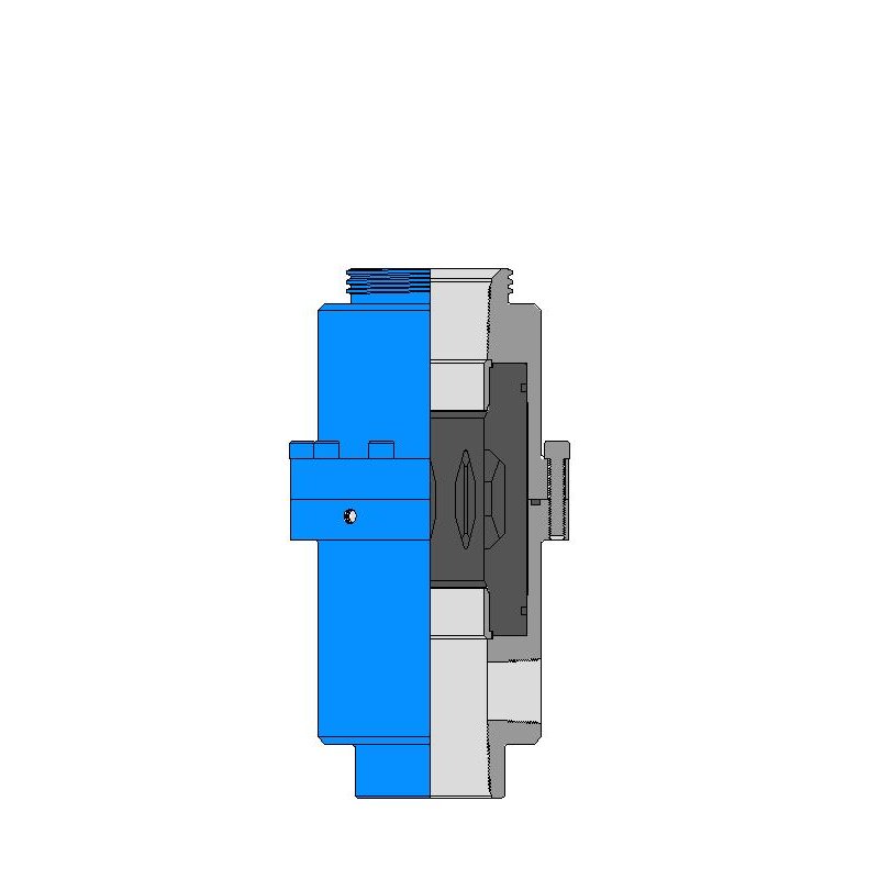
Annulus control safety valves from Baker Hughes prevent uncontrolled flow in your well’s annular space to ensure that your gas-lift operations run smoothly and safely.
You maintain downhole safety with non-elastomeric technology and a rod piston for long-term sealing durability that withstands high pressures and temperatures. Single control lines actuate the valve while a loss-of-control pressure line provides emergency closure.
Optimize production at lower operating costs. Maximize your well productivity with annulus valves designed with a large annular flow area that minimizes pressure drops
Reduce risk. Ensure safe and reliable operation with annulus safety valves configured to your operating conditions and proven in stringent prototype testing prior to deployment

Wells with planned or unplanned sustained annulus pressure (SAP) pose a considerable risk to personnel and facilities. In these situations, annulus line gate valves (a gasket, bonnet seal or stem seal) are the primary well barrier envelope elements, with no back up in case of failure.
Most O&G companies follow a double barrier well integrity management policy. In wells operated with SAP the single barrier gate valves are in breach of this policy. Annulus line gate valves also significantly increase the ‘footprint’ of the wellhead. They require regular testing, maintenance and occasional replacement, resulting in significant life cycle costs.
The Hydraulic Surface Annulus Safety (HSASTM) valve addresses all of the challenges listed above. It is installed in the wellhead VR profile, where (in wells with SAP) it becomes an independently testable element of the primary barrier envelope.

Halliburton provides proven, high-performance tubing-retrievable and wireline-retrievable subsurface safety valves (SSSV) designed to reliably shut-in (fail safe) if a catastrophic event occurs, allowing operators to maintain safe operations.

Following closely on the heels of our first VR toolkit rental order in Oman, Petroleum Technology Company (PTC) has now received its first Purchase Order for Master Surface Annulus Safety ( MSAS)Valves from an Oman based OPCO.
The MSAS Valves are installed in cases where either planned or unplanned annulus pressure exists. They uniquely facilitate a double barrier against the escape of the annulus contents, at the interface between the wellhead and the annulus line valve, while also facilitating bi-directional flow to or from the well annulus.

Surface-controlled subsurface safety valves (SCSSVs) are critical components of well completions, preventing uncontrolled flow in the case of catastrophic damage to wellhead equipment. Fail-safe closure must be certain to ensure proper security of the well. However, this is not the only function in which it must be reliable—the valve must remain open to produce the well. Schlumberger surface controlled subsurface safety valves exceed all ISO 10432 and API Spec 14A requirements for pressure integrity, leakage acceptance criteria, and slam closure.
Through decades of innovation and experience, Schlumberger safety valve flapper systems are proven robust and reliable. The multizone dynamic seal technology for hydraulic actuation of subsurface safety valves is a further improvement in reliability performance when compared with traditional seal systems in the industry.
The multizone seal technology is currently available in the GeoGuard high-performance deepwater safety valves, which is validated to API Spec 14A V1 and V1-H.

On the twenty-seventh of May, 1879, the Consolidated Safety-valve Company, a Connecticut corporation, brought a suit in equity, in the circuit court of the United States for the district of Massachusetts, against the Crosby Steam Gage & Valve Company, a Massachusetts corporation, for the infringement of letters patent No. 58,294, granted to George W. Richardson, September 25, 1866, for an improvement in steam safety-valves. The specification of the patent is as follows:
"Be it known that I, George W. Richardson, of the city of Troy, in the county of Rensselaer, in the state of New York, have invented a new and useful improvement on a safety-valve for steam generators, and I do hereby declare that the following is a full, clear, and exact description of the construction and operation of the same, reference being had to the annexed drawings, making a part of this specification, in which Fig. 1 is an end view of my improved safety-valve and its seat, as seen from the bottom; Fig. 2 is an end view of the valve alone, as seen from the bottom; Fig. 3 is a vertical section at x, x, Fig. 1, of the valve and seat in position; Fig. 4 is a vertical section at y, y, Fig. 2, of the valve alone. Similar colors and letters of reference indicate corresponding parts in the several figures A, A, is the head of the safety-valve; B, B, B, B, are wings to guide the valve into its seat, E, E; c, c, is a circular or annular flange or lip, extending over, slightly below, and fitting loosely around, the outer edge of the valve-seat, E. E; D, D, is a circular or annular chamber, into which the steam immediately passes when the valve lifts from its seat at the ground joint, F, F; E, E, is the valve-seat; F, F, is the ground joint of the valve and seat; P is the countersink or center upon which the point of the stud extending from the scale lever rests, in the usual manner. The nature of my invention consists in increasing the area of the head of the common safety-valve outside of its ground joint, and terminating it in such a way as to form an increased resisting surface, against which the steam escaping from the generator shall act with additional force after it has lifted the valve from its seat at the ground joint, and so, by overcoming the rapidly increasing resistance of the spring or scales, insure the lifting of the valve still higher, thus affording so certain and free a passage for the steam to escape as effectually to prevent the bursting of the boiler or generator, even when the steam is shut off and the damper left open.
"To enable others skilled in the art of make and use my invention, I will proceed to describe its construction and operation. To the head of the common safety-valve, indicated by all that portion of Fig. 2 lying within the second circle from the common center, I add what is indicated by all that portion lying outside of the said circle, in about the proportion shown in the figure. A transverse vertical section of this added portion is indicated, in Fig. 4, by those portions of the figure lying outside of the dotted lines, p p, p, while all that portion lying within the dotted lines, p p, p p, indicatesa transverse vertical section of the common safety-valve alone. This increased area may be made by adding to a safety-valve already in use, or by casting the whole entire. I terminate this addition to the head of the valve with a circular or annular flange or lip, c, c, which projects beyond the valve-seat, E, E, Fig. 3, and extends slightly below its outer edge, fitting loosely around it, and forming the circular or annular chamber, D, D, whose transverse section, shown in the figure, may be of any desirable form or size. This flange or lip, c, c, fitting loosely around the valve-seat, E, E, is separated from it by about 1-64 of an inch, for an ordinary spring or balance. For a strong spring or balance this space should be diminished, and for a weak spring or balance it should be increased, to regulate the escape of the steam, as required. Instead of having the flange or lip, c, c, project beyond and extend below and around the outer edge of the valve-seat, as shown in Fig. 3, a similar result may be obtained by having the valve-seat itself project beyond the outer edge of the valve-head, and terminating it with a circular or annular flange or lip, extending slightly above, and fitting loosely around, the outer edge of the flange or lip, c, c, of the valve-head; but I consider the construction shown in Fig. 3 preferable. With my improved safety-valve, constructed as now described, and attached to the generator in the usual way, the steam, escaping in the direction indicated by the arrows in Fig. 3, first lifts the valve from its seat at the ground joint, F, F, and then, passing into the annular chamber, D, D, acts against the increased surface of the valve-head, and by this means, together with its reaction produced by being thrown down wards upon the valve-seat, E, E, it overcomes the rapidly increasing resistance of the spring or balance, lifts the valve still higher, and escapes freely into the open air until the pressure in the generator is reduced to the degree desired, when the valve will be immediately closed by the tension of the spring or balance. The escape of the steam by means of this safety valve is so certain and free that the pressure of the steam in the generator or boiler will not increase beyond the point or degree at which the value is set to blow off."
The claim of the patent is this: "What I claim as my improvement, and desire to secure by letters patent, is a safety-valve with the circular or annular flange or lip, c, c, constructed in the flange or lip, c, c, constructed in the manner, shown, so as to operate as and for the purpose herein described." On the second of June, 1879, the same plaintiff brought a suit in equity, in the same court, against the same defendant, for the infringement of letters patent No. 85,963, granted to the same George W. Richardson, January 19, 1869, for an improvement in safety-valves for steam boilers or generators. So much of the specification of the patent as is involved in this suit is as follows:
"Be it known that I, George William Richardson, of Troy, in the state of New York, have invented certain new and useful improvements in safety-valves for steam boilers or generators; and I do hereby declare that the following is a full, clear, and exact description thereof, reference being had to the accompanying drawings making part of this specification, in which Fig. 1 is a vertical section of the safety-valve and its connections, taken in the plane of the axis of the valve-stem; Fig. 2, a horizontal section taken in the plane of the line, A, a, of Fig. 1; and Fig. 3 another horizontal section at the line, B, b, of Fig. 1. Fig. 4 is a vertical section taken in the plane of the axis of the valve, representing a modification of my said invention; and Fig. 5 a horizontal section thereof, taken in the plane of the line, C, c, of Fig. 4. My said invention relates to improvements in the invention described in letters patent granted to me, and bearing date the twenty-fifth day of September, 1866, which said patented invention relates to a means for providing a more free escape for the steam than could be obtained by safety-valves as constructed prior thereto, and to insure the keeping of the valve open until the pressure of the steam in the boiler or generator falls below the pressure which was required to open it; the said means so patented consisting in forming the valve with a surface outside of the ground joint, for the escaping steam to act against, the said surface being surrounded by a projecting or overlapping lip, rim, or flange, leaving a narrow escape for the steam when the valve is opened, but which although of greater diameter than the valve-seat, by reason of the said lap, presents a less area of opening for the escape of steam than is produced at the valve-seat, so that the steam which escapes through the area between the valve shall exert pressure against the said surrounding surface, and thereby not only open the valve completely, but hold it up until the pressure of the steam in the boiler falls below the pressure by which the valve was opened.
"One part of my pressent invention relates to a means for regulating or adjusting the area of the aperture for the escape of the steam after acting on the said surface outside of the valve-seat, so that the valve may be set to close at any desired pressure below the pressure which will open it; and this part of my invention consists in making the aperture or apertures for the escape of the steam, after it has acted on the said surface outside of the valve-seat, adjustable. * * * I will first describe the preferred mode of application of my said invention, as represented in Figs. 1, 2, and 3 of the accompanying drawings. In the said figures, a represents the valve-seat, which is to be attached to a steam boiler or generator in the usual or any other suitable manner, and which is formed, in the usual manner, with a beveled seat from the valve, b, fitted thereto by what is well-known as a "ground joint." * * * It is desirable that, so soon as the pressure of the steam in the boiler or generator reaches the pressure at which it should be relieved, the safety-valve should open wide for the free escape of steam, and that the valve should remain open until the pressure in the boiler is reduced below the pressure by which the valve was opened, and that it should be so organized that the engineer may be able to adjust it so that it will close at any desired number of pounds pressure below the pressure at which it was opened. To accomplish these results was the main object of my said invention.
"To the upper surface of the valve, I secure a cap-plate or annulus, m, formed with a downward-projecting flange, n, at its outer periphery, leaving an annular space, o, all around between the outer periphery of the valve and the inner periphery of the flange, n, of the said cap. And the upper surface of the valve-seat, a, is extended all around, a little beyond the outer peripheryof the flange, n, of the cap, leaving an annular surface, p, surrounded by an upward-projecting rim, q, the plane of the upper edge of which, when the valve is closed, extends a short distance above the plane of the lower edge of the flange, n, of the cap. The said cap-plate, m, is connected with the top of the valve by studs, r, r, or cast with it, in such manner as to leave an open space, s, between the two, for the passage of steam to the central aperture, t, in the cap, through which steam can escape when the valve is lifted from its a threaded ring, u, that can be by a projecting cylindrical flange, threaded on the outside, to which is fitted a threaded ring, u, that can be turned up or down to any desired elevation, and there secured by a set-screw, v. The disk-like projection, f, on the valve rod or stem, e, extends over the said central aperture, t, in the cap-plate, m, and at such an elevation that the upper edge of the adjustable ring can be set in contact with it, or let down so far below it as to leave sufficient space for the free escape of steam.
"From the foregoing it will be seen that, when the pressure of steam in the boiler or generator becomes sufficient to lift the valve from its seat, it acts against the surface of the annular space, o, between the bevel of the valve-seat and the downward-projecting flange, n, of the cap, to assist in lifting and holding up the valve, particularly when the valve is borne down by the tension of a spring, which presents an increasing resistance as the valve is lifted. If the projecting rim, q, were in the same plane with the lower edge of the flange, n, the diameter of these parts being greater than that of the valve-seat, on the lifting of the valve and cap, the area of the opening between the flange, n, of the cap, and the projecting rim, q, would be greater than the area of the opening between the valve and its seat, just in proportion as the diameter of the one is greater than the other, and the steam escaping from the valve would pass unchecked between the flange, n, and rim, q, and would not exert any force against the surface of the annular space, o; but, as the rim, q, extends above the lower edge of the flange, n, of the cap-plate, it follows that the aperture between the valve and its seat, by the lifting of the valve, is always greater than the aperture between the flange, n, and the rim,q, and hence the escaping steam, by its elastic force, will act against the surface of the annular space, o, to assist in lifting and holding up the valve until the pressure in the boiler or generator falls below the pressure by which the valve was first opened. The difference between the pressure against which the valve will close and the pressure by which it will be opened will depend upon the distance between the outer periphery of the flange, n, of the cap-plate and the inner periphe y of the projecting rim, q. To render this adjustable, the area of the aperture for the escape of steam beyond the valve-seat must be adjustable. This is effected by the raising or lowering of the ring, u. If it be set to its lowest position, the steam escaping from the valve will be free to escape between the top of the valve and the cap, through the central aperture, and thence between the upper edge of the ring, u, and the disk, f, without materially aiding to lift or hold up the valve; but, by setting the ring, u, nearer to the under surface of the disk, f, and thereby reducing the space for the escape of steam, it will be caused to act, by its elastic force, against the annular space, o, of the cap-plate, and thus assist in lifting the valve and holding it up.
"I have described and represented this as the simplest mode of adjusting the area of the aperture for the escape of the steam after it passes the valve-seat; but it will be obvious that the same result may be attained by equivalent means, such, for instance, as making the ring, q, in adjustable segments, so that its diameter can be increased or diminished; but this would be mont complicated than the mode first and fully described; and it will also be obvious that the devices for holding up the valve may be inverted, as represented in Figs. 4 and 5 of the accompanying drawings, in which a" is the valve-seat, and b" the valve, with its beveled ground joint, the valve-seat, a" having a flat annular surface, c", beyond the bevel, and the valve an annular surface, d", with a down ward-projecting flange, e", the lower edge of which, when the valve is closed, extends a little below the plane of the surface, c", of the valve-seat, and a narrow annular space being left for the escape of steam between the inner periphery of the said flange and the outer periphery of the valve-seat, a", as set forth in my patent of September 25, 1866."
The claim of the patent is as follows: "What I claim as new, and desire to secure by letters patent, is the combination of the surface beyond the seat of the safety-valve, with the means herein described for regulating or adjusting the area of the passage for the escape of steam, substantially as and for the purpose described."
The answers in the two suits set up want of novelty, and cite, as anticipating patents, three English patents: one to Charles Ritchie, No. 12,078, August 3, 1848; one to James Webster, No. 1,955, July 12, 1857; and one to William Hartley, No. 2,205, August 19, 1857; also an English publication made in 1858, called "The Artizan." Infringement is denied, and it is averred that the valves which the defendant makes and sells are the inventions of George H. Crosby, and are described in two patents granted to him, and owned by the defendant: one, No. 159,157, dated Junuary 26, 1875; and the other, No. 160,167, dated February 23, 1875. The same proofs were taken in the two suits, and they were heard together in the circuit court. In each suit that court made a decree dismissing the bill, (7 Fed. Rep. 768,) and from each decree the plaintiff has appealed.
When Richardson applied for his patent of 1866 his claim read thus: "What I claim as my improvement, and desire to secure by letters patent, is increasing the area of the head of the common safety-valve, outside of the ground joint, F, F, and terminating this addition with the circular or annular flange or lip, c, c, constructed in the manner, or substantially in the manner, shown, so as to operate as and for the purpose herein described." This claim was rejected as defective, because not for a device, and it was amended to read as granted.
In this application for the patent of 1869 there were two claims. The second related to means for preventing the guides and stem of the valve from binding, and was rejected as not new, and stricken out, though the descriptive matter on which it was founded was retained. The first claim, as applied for, was this: "What I claim as new, and desire to secure by letters patent, is combining with the surface beyond the beveled, or equivalent, seat of a safety-valve, the means herein described, or the equivalent thereof, for regulating or adjusting the area of the passage for the escape of steam beyond the bevel, or equivalent, seat, substantially as and for the purpose described." This claim was amended, on suggestions made by the patent-office, to read as granted.
The view taken by the circuit court, in dismissing the bills, was that some valves had been made before 1866, which embodied the same general principle as Richardson"s, and were of some value, operating through the expansive power of steam exerted upon an additional chamber outside of the ground joint; and that what Richardson did was to so regulate the action of the chamber outside of the ground joint, by a crack or opening between the lip of the valve and its main body, that the steam would be confined or huddled, when it sought to escape from the chamber, and so the valve would be held up just long enough, and could fall rapidly before too much steam was lost. But the cases went off on the question of infringement, and the circuit court found that while the defendant"s valve employed an additional surface to lift the valve as soon as it began to blow, and the pressure was regulated in part by a stricture, it differed from the plaintiff"s, in that the additional area was not outside of the ground joint, but inside, and was not acted on independently of the valve itself, but was a part of it, and the escaping steam did not act at all by impact, but wholly by expansion. The conclusion was that, as Richardson was not the first to apply the idea of an additional area or of a stricture, he could not enjoin a valve which resembled his only in adopting such general ideas, and that his claims did not cover a valve having the mode of operation of the defendant"s.
Edward H. Ashcroft, as assignee of William Naylor, obtained reissued letters patent of the United States, No. 3,727, dated November 9, 1869, on the surrender of letters patent No. 58,962 issued to said Naylor, October 16, 1866, for an improvement in safety-valves. Ashcroft brought a suit in equity, in the circuit court of the United States for the district of Massachusetts, against the Boston & Lowell Railroad Company, for the infringment of reissue No. 3,727. The infringement consisted in the use of valves constructed according to the patent of 1866 to Richardson. The court dismissed the bill, (5 O. G. 725; 1 Holmes, 366; 1 Ban. & A. 215), and, on an appeal to this court by the plaintiff, the decree was affirmed. 97 U. S. 189. In view of an English patent, No. 1,038, granted to Charles Beyer, April 25, 1863, it was held by this court that Naylor was not the first person who devised means for using the recoil action of steam to assist in lifting the valve, or who invented the combination, in a spring safety-valve, of an overhanging downward curved lip, with an annular recess surrounding the valve-seat, into which steam is deflected as it issues between the valve and its seat. In speaking of the invention of Richardson, as described in his patent of 1866, this court said: "His invention, as he describes it, consists in increasing the area of the head of the common safety-valve outside of its ground joint, and terminating it in such a way as to form an increased resisting surface, against which the steam escaping from the generator shall act with additional force, after lifting the valve from its seat at the ground joint, and so, by overcoming the rapidly increasing resistance of the spring or scales, will insure the lifting of the valve still higher, thus affording so certain and free a passage for the steam to escape as effectually to prevent the bursting of the boiler or generator, even when the steam is shut off and the damper left open. Safety-valves previously in use were not suited to accomplish what was desired, which was to open for he purpose of relieving the boiler, and then to close again at a pressure as nearly as possible equal to that at which the valve opened. Sufficient appears to show that Richardson so far accomplished that purpose as to invent a valve which would open at the given pressure to which it was adjusted, and relieve the boiler, and then close again when the pressure was reduced about two and one-half pounds to the inch, even when the pressure in the generator was one hundred pounds to the same extent of surface, which made it, in practice, a useful spring safety-valve, as proved by the fact that it went almost immediately intc general use. * * * When the valve opens, the steam expands and flows into the annular space around the around joint. Its free escape, which might otherwise be too free, is prevented by a stricture or narrow space formed by the outer edge of the lip and the valve-seat. By these means, the steam escaping from the valve is made to act, by its expansive force, upon an additional area outside of the device, as ordinarily constructed, to assist in raising the valve." On these views, it was held by this court that although important functions, not very dissimilar in the effect produced, were performed by the two valves there in controversy, the means used and the mode of operation were substantially different in material respects.
In the present case, the defendant has introduced in evidence the beforenamed English patents to Ritchie, Webster, and Hartley, and the English patent to William Naylor, No. 1,830, granted July 1, 1863; and also letters patent of the United States, No. 10,243, granted to Henry Waterman, November 15, 1853, and the reissue of the same, No. 2,675, granted to him July 9, 1867. In view of all these patents, and of the state of the art, it appears that Richardson was the first person who described and introduced into use a safety-valve which, while it automatically relieved the pressure of steam in the boiler, did not, in effecting that result, reduce the pressure to such an extent as to make the use of the relieving apparatus practically impossible, because of the expenditure of time and fuel necessary to bring up the steam again to the proper working standard. His valve, while it automatically gives relief before the pressure becomes dangerously great, according to the point at which the valve is set to blow off, operates so as to automatically arrest with promptness the reduction of pressure when the boiler is relieved. His patent of 1866 gave a moderate range of pressure, as the result of the proportions there specified, and his patent of 1869 furnished a means of regulating that range of pressure, by a screw-ring, within those narrow limits which are essential in the use of so subtle an agent as steam.
In regard to all the abouve patents, adduced against Richardson"s patent of 1866, it may be generally said, that they never were, in their day, and before the date of that patent, or of Richardson"s invention, known or recognized as producing any such result as his apparatus of that patent produces, as above defined. Likenesses in them, in physical structure, to the apparatus of Richardson, in important particulars, may be pointed out, but it is only as the anatomy of a corpse resembles that of the living being. The prior structures never effected the kind of result attained by Richardson"s apparatus, because they lacked the thing which gave success. They did not have the retarding stricture which gave the lifting opportunity to the huddled steam, combined with the quick falling of the valve after relief had come. Taught by Richardson and by the use of his apparatus, it is not difficult for skilled mechanics to take the prior structures and so arrange and use them as to produce more or less of the beneficial results first made known by Richardson; but, prior to 1866, though these old patents and their descriptions were accessible, no valve was made producing any such results. Richardson"s patent of 1866 states that the addition to the head of the valve terminates in an annular lip, which fits loosely around the valve-seat, and is separated from it by about one sixty-fourth of an inch for an ordinary spring, and a less space for a strong spring, and a greater space for a weak apring, forming an annular chamber, and regulating the escape of the steam; that the steam, when the valve is lifted, passes beyond the valve-seat, and into the annular chamber, and acts against the increased surface of the valvehead, and thus overcomes the increasing resistance of the spring due to its compression, and lifts the valve higher, and the steam escapes freely into the open air, until the pressure is sufficiently reduced, when the spring immediately closes the valve. It is not shown that, before 1866, any known valve produced this result. On the contrary, Richardson testifies that, for about 20 years before 1866, he was acquainted with safety-valves in practical use, by working in the locomotive repair-shops of railroad companies, part of the time as foreman, and as a locomotive engineer, and that he never, before his invention, knew, in practical use or on sale, of any spring loaded safety-valve capable of opening to relieve the boiler when the working pressure was exceeded, and of automatically closing with a small loss of working pressure. He also says that he was in England, for about four months, in 1873, bringing his valve to the notice of officials in the shops of some of the largest railroad companies, (his valve being one especially useful on locomotive engines on railroads;) that, while he was in England, he found no man who professed to be acquainted with, or to have heard of, a safety-valve which would automatically open and relieve the boiler at a predetermined working pressure, and automatically close when such working pressure had been slightly reduced, or who admitted that such a valve could be made untill he had seen Richardson"s valve work; that the master mechanics at the shops named did not believe he could make a valve close within 25 pounds of the blowing-off point; that he showed them the working of his valve with no excess beyond working pressure, and with but from 3 to 5 pounds reduction from a pressure of 130 pounds per square inch in the boiler; that he did not hear, in England, of any of the Ritchie, Webster, or Hartley valves, but heard the Naylor valve blow; and that, when it blew, the steam rose several pounds above the point where it commenced to blow, and it did not close promptly, tightly, or suddenly. There is no evidence to contradict, or vary the effect of, this testimony.
Thomas Adams, of Manchester, England, who has spent a life-time in the manufacture and practical working of safety-valves, testifies that the Ritchie and Webster valves have never been in use practically in England, and the Hartley only in two or three cases, when it was a failure; that he himself has made and applied, in England, about 15,000 of Richardson"s valves; that, if loaded at 120 pounds per square inch, his valve returns to its seat with a very small loss of pressure; that the Beyer valve, loaded at 120 pounds, reduces the pressure 30 pounds, before returning to its seat; and that Naylor"s has been superseded by Richardson"s. It appears to have been easy enough to make a safety-valve which would relieve the boiler, but the problem was to make one which, while it opened with increasing power in the steam against the increasing resistance of a spring, would close suddenly and not gradually, by the pressure of the same spring against the steam. This was a problem of the reconciliation of antagonisms, which so often recurs in mechanics, and without which practically successful results are not attained. What was needed was a narrow stricture, to hold back the escaping steam, and secure its expansive force inside of the lip, and thus aid the direct pressuro of the steam from the boiler, in lifting the valve against the increasing tension of the spring, with the result hat, after only a small, but a sufficient, reduction in the boiler pressure, the compressed spring would, by its very compression, obtain the mastery and close the valve quickly. This problem was solved by Richardson and never before. His patent of 1869 describes the arrangement and operation of the whole apparatus, with the adjustable ring, thus: When the pressure of the steam lifts the valve, the steam acts against the surface of an annular space between the bevel of the valve-seat and the downward-projecting flange of the cap-plate, to assist in holding up the valve against the increasing resistance of the spring. The aperture between the valve and its seat is always greater than that between the flange and the upward-projecting rim, and thus the steam in the annular space assists in holding up the valve till the boiler pressure falls below that at which the valve opened. The difference between the closing pressure and the opening pressure depends on the distance between the flange and the rim. There is a central aperture in the cap, through which the steam escapes when the valve is lifted, which is surrounded by a projecting cylindrical flange, threaded on the outside, to which is fitted a threaded ring, which can be turned up or down, and secured by a set-screw. By this means, the area of the aperture for the escape of steam beyond the valve-seat is adjustable, the space being largest when the ring is down and smallest when the ring is up.
Ritchie"s patent, in speaking of his valve, says: "This valve is weighted by a helical spring, i, (shown at Fig. 2,) of sufficient power according to the required pressure of the steam; and, when it is intended to be used as a reserve safety-valve, I place the spring around that part of the stem below the valve, that is to say, within the boiler, as shown at Fig. 2. The advantage of this form of construction of valve over the ordinary valve is as follows: As soon as the pressure of the steam raises the valve from its seat, the flange,h, being exposed to the pressure of the steam, presents an increased surface, which compensates for the increasing resistance of the helical spring, i, until the valve has been raised to a height equal to the area of the steam-way, when it allows the steam or vapor to escape freely." In an article in the Artizan, published in England, in July, 1858, signed by Ritchie, and referring to his patent of 1848, it is said of his valve: "The top area being made double that of the under side or steam-way, such a valve would quickly reduce the pressure in the boiler to half that at which the valve lifted; and so, also, of other proportions. Hence it is chiefly suited for a reserved valve." This shows the existence of the very evil which Richardson remedied. Ritchie"s patent and publication say nothing about any stricture.
The evidence in the present case shows, satisfactorily, that valves made in conformity with the measurements of the drawing of Ritchie"s patent do, in practice, reduce the pressure in the boiler to such an extent, after that pressure is properly relieved, and before they close, as to involve great loss of time and consumption of fuel before the initial pressure is restored. The experimental valves produced by the defendant as structures made according to Ritchie"s patent vary from the dimensions of his drawing, and the variations are those which result from the instructions given by Richardson in his patents. Ritchie gives no information how to make a valve work at a predetermined pressure, or how to make it work with a small range of difference between the opening and closing pressures, or how to proportion the strength of the spring and the size of the stricture to each other. The same thing is true of the Webster and the Hartley patents. The Webster patent shows a huddling chamber and a stricture. But the evidence shows that valves made with the proportions shown in the drawings of Webster work with so large a loss of boiler pressure, before closing, as to be practically a d economically worthless. Webster"s patent describes a means of making the area fot the escape of steam adjustable consisting in adjusting up and down, on a smooth valve-stem, a sliding collar or flange, and fixing it in place by a set-screw. But it does not show the screw-ring of Richardson, with its minute delicacy of adjustment and action. Nothing further need be said as to the Hartley valve or the Beyer valves.
The original patent to Waterman was issued in 1853. His attention had been turned to the subject of safety-valves for locomotive-engines. He invented what is described in that patent, but he testifies that before 1866 he never saw a safety-valve capabel of keeping the pressure at a point not above working pressure, and of relieving the boiler with but a small loss of pressure; that his valve would let the steam down about 15 pounds, and was not practical lfor an ordinary locomotive; and that the Richardson valve, when introduced, went at onec into general use. The Waterman valve had a supplemental surface, on which the steam acted to aid in the raising of the valve; and this was shown in the drawing of Waterman"s original patent, but the specification did not describe it. Waterman"s original patent did no show the use of a spring, and prior to its reissue his valve had not been made with a spring. After Richardson obtained his patent of 1866, and Waterman knew of Richardson"s valve,—they combined the interests in their two patents, and the reissue of Waterman"s was obtained, with the co-operation of Richardson, he signing, as a witness, the specification of the reissue. That specification, granted in 1867, describes an overhanging part of the valve as increasing its area outside of and beyond the ground joint and a concentric rim or ledge, which directs the steam upward against such overhanging part of the valve, so that the valve is assisted in rising. The specification was drawn in view of Richardson"s patent and valve, and for the purpose of making a claim, which was then made, and which was not in Waterman"s original patent, to a combination of the concentric rim or ledge with the overhanging part of the valve. The specification states that the valve and its seat are so constructed that the escaping steam will act on an increased area of the valve after it has risen from its seat, and strike the overhanging or projecting annular surface above and outside of and beyond the ground joint. It also states that a proper modification of the overhanging or projecting annular surface will modify the force of the steam; that if such surface be large the valve will be opened suddenly and discharge so much steam that the pressure in the boiler will be considerably reduced before the valve closes; that such surface may be made so small that but little more than the surplus steam will escape; that the success or efficiency of the valve will depend on a proper proportion between the overhanging annular surface and the concentric rim or ledge, because, if a free discharge of steam between them is allowed, the valve will not be assisted in rising, and if the escape of steam is too small, the valve will rise too easily, and remain open too long, and the steam will be so much reduced in pressure as seriously to impair the economical and efficient action of the apparatus; and directions are given as to the sizes of the overhanging part, and of the ledge or rim, and of the opening, for a valve of a specified diameter acting with a specified pressure of steam. Nothing of all this was found in the specification of the original Waterman patent. It therefore has no effect, as against Richardson"s patent of 1866, to destroy the validity of that patent.
Richardson is, therefore, entitled to cover, by the claim of his patent of 1866, under the language, " a safety-valve with the circular or annular flange or lip, c, c, constructed in the manner, or substantially in the manner, shown, so as to operate as and for the purpose herein described," a valve in which are combined an initial area, an additional area, a huddling chamber beneath the additional area, and a strictured orifice leading from the huddling chamber to the open air, the orifice being proportioned to the strength of the spring, as directed. The direction given in the patent is that the flange or lip is to be separated from the valve-seat by about one sixty-fourth of an inch for an ordinary spring, with less space for a strong spring, and more space for a weak spring, to regulate the escape of the steam, as required. As matter of law, this description is sufficient, within the rule laid down in Wood v. Underhill, 5 How. 1, and it is not shown to be insufficient, as a matter of fact. Richardson is also entitled to cover, by the claim of his patent of 1869, under the language, "the combination of the surface beyond the seat of the safetyvalve, with the means herein described, for regulating or adjusting the area of the passage for the escape of steam, substantially as and for the purpose described," the combination with the surface of the huddling chamber, and the strictured orifice, of a screw-ring, to be moved up or down to obstruct such orifice more or less, in the manner described.
The Richardson patents have a disk valve, an annular huddling chamber, an annular stricture at the outer extremity of the radii from the center of the valve, an additional area which is radially beyond the disk valve, and a cylindrical steam-way. But, before 1866, an annular form of safety-valve was well known. Such a valve necessarily requires an annular steam-way. In the defendant"s valve, complainant"s Exhibit A, the same effects, in operation, are produced as in the Richardson valve, by the means described in Richardson"s claims. In both structures the valve is held to its seat by a spring, so compressed as to keep the valve there until the pressure inside of the boiler is sufficient to move the valve against the pressure of the spring, so that the steam escapes through the ground-joint into a chamber covered by an extension of the valve, in which chamber the steam acts expansively against the extended surface, and increases the pressure in opposition to the increasing pressure of the spring, and assists in opening the valve wider. This chamber, in the defendant"s valve, has, at its termination, substantially the same construction as Richardson"s valve, namely, a stricture, which causes the steam to act, by expansive force, against the extended surface of the valve; and in both valves, after the pressure of the steam has been somewhat reduced in the boiler, the closing movement is quickened, as the valve nears its seat, in consequence of the reduced pressure of the steam on the extended surface, and the valve comes suddenly to its seat. In the Richardson valve, the valve proper is a disk, and the extended surface is an annulus surrounding the disk, while, in the defendant"s valve, the valve proper is an annulus, and the extended surface is a disk inside of the annulus. But this is a mere interchange or form between the valve proper and the extended surface, within the skill of an ordinary mechanic.
There is one structural difference between the two valves, which is now to be mentioned. In the Richardson valve, all the steam which escapes into the open air escapes from the huddling chamber, through a stricture which is smaller than the aperture at the ground joint. In the defendant"s valve, the valve proper has two ground joints, one at the inner periphery of the annulus, and the ther at its outer periphery, and only a part of the steam, namely, that which passes through one of the ground joints, passes into the huddling chamber and then through the stricture; the other part of the steam passing directly from the boiler into the air through the other ground joint. But all of that part of the steam which passes into the huddling chamber and under the extended surface, passes through the constriction at the extremity of such chamber, in both valves; the difference being only one of degree, but with the same mode of operation. In the Richardson patent of 1869, the stricutre is regulated as to size by an adjustable screw-ring. In the defendant"s valve, there is a screw-ring or sleeve, which closes the escape orifices from the central chamber, more or less. In the defendant"s valve, the huddling chamber is at the center instead of the circumference, and is in the seat of the valve under the head, instead of in the head, and the stricture, instead of being at the circumference of the head, is at the circumference of the seat of the valve. But this is only the use of means equivalent to those shown by Richardson, while the mode of operation of the parts of the mechanism is the same, in their relation to each other, and the result is the same.
Richardson"s invention brought to success what prior inventors had essayed and partly accomplished. He used some things which had been used before, but he added just that which was necessary to make the whole a practically valuable and economical apparatus. The fact that the known valves were not used, and the speedy and extensive adoption of Richardson"s valve, are facts in harmony with the evidence that his valve contains just what the prior valves lacked, and go to support the conclusion at which we have arrived on the question of novelty. When the ideas necessary to success are made known, and a structure, embodying those ideas, is given to the world, it is easy for the skillful mechanic to vary the form by mechanism which is equivalent, and is, therefore, in a case of this kind, an infringement.

Safety valves, when properly maintained, can last a long time—upwards of 30 years or more. Much more. Recently, a century-old valve arrived at NASVI for repair. After machining and lapping […]
William Rock III, NASVI Valve Disassembler Since 2001 When a valve arrives at our facility for remanufacturing, William Rock III (Bill) is ready and waiting on the front line. He […]
Bronze, steel and stainless steel safety relief valves for air, gas, steam, liquid and vacuum service that meet ASME Section VIII, ‘UV’; Section I, ‘V’, are National Board certified and […]
When it comes to safety valve experience NASVI employees have a mountain of knowledge. Guess how many years of collective experience these three long-time employees have in this short video. […]
This direct spring-operated pressure relief valve, part of the Series 60 and 80, uses special internals and soft seats for optimum, accurate performance. Of course, we have them in stock. […]
The NASVI team goes the extra step in safety valve quality control. Before we ship any valve, we set and test them to the end user’s specifications. This is an […]
Q: My customer has a 2-inch line. Do I need to sell them a 2-inch safety valve? A: Safety valves should be sized and selected based on the set pressure […]
Not only is Kunkle’s 6252/6254 among their largest valves, also it’s a very sought-after one. You guessed it; we keep several in stock. For general application, it is suitable for […]
Valve manufacturers are not immune from the supply chain issues plaguing most industries right now. It’s predicted that it will take some time for shipping channels to be adjusted. NASVI […]
With supply chain disruptions hitting manufacturers, it’s important to be proactive as we approach heating season. With 35,000 relief and safety valves in stock & same day shipping, our extensive […]
Supply the following information: Example: 1. Quantity of Valves 4 2. Size of Valve Inlet and Outlet 1 ½” x 2” 3. Type, Model or Figure Number 1905FC 4. Manufacturer Consolidated 5. Inlet and […]
If you’re searching for a new Consolidated 1700 Series Maxiflow™ safety valve, or the 2700 and 1900-P1 Series economizer valves, look no further than NASVI. We’re the only company in […]
Did you know that NASVI has 35,000 safety & relief valves ready to ship at a moment’s notice? Or that warehouse is so huge (63,000 square feet!) we have a […]
NASVI pressure tests over 150 valves every day. Watch the process from adjusting the blow down ring to field service guidelines and performing the test pop, to sealing and shipping […]
If your customers are requesting a Kunkle liquid relief valve, model 218, then it’ll come as no surprise to you that not all distributors stock them and the manufacturer’s lead […]
A cracked valve, a broken part. There are always unwelcome surprises during a scheduled or unplanned shut down. Operations need to be back up and running ASAP. Don’t wait 7-10 […]
A No Brainer. Wearing face masks and social distancing is a no brainer. It isn’t pleasant, but you do what you have to do. Selling safety valves is also a […]
If you’re on the hunt for a new Consolidated 1700 Series Maxiflow™ safety valve, or the 2700 and P1 Series economizer valves, look no further than NASVI. We’re the only […]
What’s the purpose of a drip pan elbow? It provides a means to handle condensate from safety valves used in steam applications. Where are drip pan elbows used? The drip […]
When you sell safety valves, your customers are under pressure to get what they need fast. That’s why NASVI stocks the largest selection of Kunkle Valves for a variety of […]
Suggest a NASVI Valve Exchange Program. If your customer has several safety valves in need of repair but can’t afford to shut down for lengthy repairs, there’s an easy solution: […]
Offer remanufactured safety valves and watch sales grow. More companies today have found that it makes sense to rely on remanufactured safety valves. For most industrial uses, remanufactured valves offer […]
Offer NASVI’s quick turnaround on repair and testing services. At NASVI, our repair services are designed to keep: Your customer’s safety and relief valves at peak operating efficiency, and Put […]
You don’t have to be an expert in the field of safety and relief valves to sell them because that’s our job. And we’re only a phone call away. We’ll […]
Today, many companies are finding when maintenance budgets need to be stretched; a safe way to save is to rely on remanufactured safety valves. For most industrial uses, remanufactured valves […]
Increase profits, make our new Repair Facility your first stop. North American’s new Service Center is equipped to handle any safety valve repair. NASVI has the specifications for nearly every […]
Our goal is to make it easy for you to profit from the sales of safety and relief valves. Call us for assistance. We can help you with sales planning, […]
Earlier this year, I shared a little product education on safety valves that can make you look really smart to customers, which usually means more orders for everything you sell. […]
• More than 35,000 valves in 3,100 varieties • Currently set and ship over 200 valves per day • We repair over 40 valves a week with plenty of capabilities […]
Offer North American’s remanufactured safety valves as an alternative and watch your sales grow. Many companies have found that it makes sense to rely on remanufactured safety valves. For most […]
Our repair service center is designed to keep your customer’s safety and relief valves at peak operating efficiency. In addition to an experienced, skilled staff, NASVI’s Service Center is equipped […]
Our giant inventory and remarkable selection awaits your call. One of the customers recently inquired about the availability of five 4-inch liquid flanged valves. The end user had made a […]
Today, many companies are finding when maintenance budgets need to be stretched; a safe way to save is to rely on remanufactured safety valves. For most industrial uses, remanufactured valves […]
Our repair service center is designed to keep your customer’s safety and relief valves at peak operating efficiency. And put extra profits in your pocket. North American’s Service Center is […]
Offer NASVI’s quick turnaround on repair and testing services. At NASVI, our repair services are designed to keep: Your customer’s safety and relief valves at peak operating efficiency, and Put […]
For some reason I get asked pretty frequently if I’m a surgeon. Believe me, you don’t want me operating on you. I tell people I’m the Safety Value Doctor because […]
Offer NASVI’s quick turn-around on repair and testing services. Over the years, our Service Center has proven popular with maintenance managers. It allows your customer’s plant to have their valves […]
Baker Hughes has commercialized its Reconnect technology, the company announced at a news conference on 20 September at the SPE Annual Technical Conference and Exhibition in Florence, Italy. The system was developed by BJ Servicesas a technology to restore surface control to subsurface safety valves.
The system provides an alternative for re-establishing surface hydraulic control to surface-controlled subsurface safety valves (SCSSVs) that are inoperable due to compromised control lines or if the installation of a storm choke is undesirable, Mark Embrey, senior sales rep for Baker Hughes capillary services, explained at the news conference.
This technology is also a viable option for wells that were not completed with SCSSVs. It includes a wireline-retrievable safety valve, a through-tubing replacement control line that strings into the new valve assembly and a wellhead adapter. Installation requires a minimal crew and equipment suitable for almost any platform or wellsite, according to Baker Hughes.
SCSSVs are designed to stop flow in the event of a catastrophic failure. They are installed in the production tubing and are mandatory in most offshore wells and some land wells. Primary SCSSVs are held open by hydraulic pressure from a control line that runs through the annulus to the surface. If pressure in the control line is lost, such as during an emergency shutdown or if the line is cut, the valve will close and revert to its fail-safe closed position, stopping flow from the well.
Traditionally, a storm choke would be installed or a workover intervention would be performed to regain surface control. But the Reconnect system does not require a workover rig. Mr Embrey adds that the new system can be customized “to fit almost any wellhead and safety valve out there.”
In one GOM installation, a mature well developed a leak in the control line of its subsurface safety valve. Injecting sealants did not repair the leak. The operator considered installing a velocity valve, but the well was scheduled for a plug-and-abandonment operation for one zone and the perforation of a new zone. Adjusting and re-adjusting a velocity valve for the new zone was expected to be time-consuming and expensive because of the well’s remote location.
The operator installed the Reconnect system, which provided flexibility to vary the well’s production rate without the intervention required to pull the velocity valve and adjust the differential pressure settings. In addition, the operator could perform mandatory testing of the downhole safety valve without the added cost of a lift boat previously required due to the small platform’s limited crane capacity and deck space.


 8613371530291