
blowdown ring in safety valve in stock

A fire-tube boiler can be fitted with one or more safety valves on the top of its shell, with each set to open when the boiler reaches its design pressure. Noisolation valvesor restrictions should be integrated between the safety valve(s) and boiler. If the valves are not installed directly onto the boiler shell, the pipework connecting the valves to the boiler must be kept clear of blockagesand water, and this must be confirmed by periodic testing.
Once a safety valve opens, steam is discharged via the exhaust pipe. Exhaust pipes must be designed to encounter as few bends as possible, be as short as possible, to have no reduction in pipe section (no internal pipe diameter reduction), and should lead to asafe point of discharge(typically outside the boiler house).
Water must be drained from the safety valve or exhaust pipework via a drainpipe. Drainpipes may be connected to holes drilled into the lowest section of the exhaust pipework, or, directly to drain holes in the safety valve body; these drains are not to be confused with the blowdown ring locking bolt, if one is fitted.
Where two safety valves are fitted, it is common that one is set just belowthe boiler’s design pressure. It is vital that each safety valve permits the full flow of steam produced when the boiler is operating at maximum capacity i.e. when the boiler is producing the maximum amount of steam it can possibly produce. If safety valves are sized correctly, a boiler can be firing at full capacity without the steam pressure exceeding design limits (because the safety valve(s) relieves pressure at a faster rate than it is accumulated).
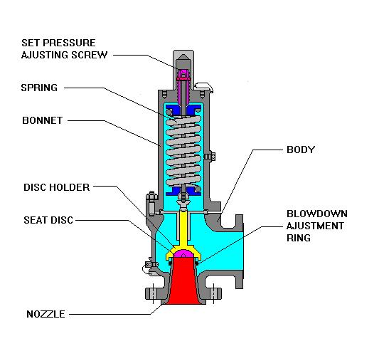
There are various types of safety valve, including high lift and improved high lift valves, which use the force of escaping steam to open a winged valve plug to achieve greater steam flow rates. In addition to this, some valves integrate a pistonat the bottom of the spring chamber. The piston has a larger surface area than the valve plug, which leads to the valve opening with a definitive ‘pop’ sound.
Some boiler safety valves include a blowdown ring. The blowdown ring can raise or lower the valve seat ring and is used to control the amount of blowdown through the valve. This ring is locked by a bolt that protrudes through the valve and into the adjusting ring segments.
Boiler safety valves should be fitted with an easing gear (looks like a handle), used, when necessary, to rapidly release boiler pressure. Easing gears can also be used for testing a safety valve, ensuring the spindle has freedom of movement and that the valve operating mechanism functions as intended. Easing gear testing is often not conducted due to operators having difficulty with the valves resealing, but this is generally only the case with valves that are not tested often enough. Actuating the easing gear several times is often all it takes to dislodge debris from the sealing area and allow the valve to seal again. For safe operation, the easing gear handle is usually connected via steel cables to an area neighbouring the boiler.
Like pressure gauges, all safety valves should be stripped, inspected, and calibrated, at least once a year; maintenance usually occurs during statutory inspections. Calibration of each valve should be conducted by a competent person, and any valve adjustment (including the blowdown ring) should be approved and sealed by the authorised inspector. After testing and calibration, all valves should be correctly marked, suitable certificates issued, and accurate records maintained.
An accumulation test can be conducted to ensure a safety valve can relieve over-pressure steam when the boiler burner is operating at maximum capacity. Accumulation testing of safety valves must be repeated after any alterations are made to the boiler e.g. replacement of a safety valve, fuel change, or changes to the control system. If, during an accumulation test, boiler pressure rises by more than 10% of its design pressure, the test must be aborted. Before the boiler is re-tested, amendments must be made to either the safety valve relieving capacity, thesafety valve exhaust pipework, or the boiler’s steaming capacity, to ensure the 10% limit is never exceeded.
Reliefand safetyvalves prevent equipment damage by relieving over-pressurisation of fluid systems. The main difference between a relief valve and a safety valve is the extent of opening at the set-point pressure.
A relief valve gradually opens as the inlet pressure increases above the set-point. A relief valve opens only as necessary to relieve the over-pressure condition. Relief valves are typically used for liquid systems.
A safety valve rapidly‘pops’ fully openas soon as the pressure setting is reached and will stay fully open until the pressure drops below the reset pressure. The reset pressure is lower than the actuating set-point pressure. The difference between the actuating pressure set-point, and the pressure at which the safety valve resets, is called blowdown. Safety valves are typically used for gas or vapour systems.
A safety relief valve may open fully, or proportionally, once the pressure setting is reached. SRVs may be used for any fluid system (gas, liquid, or vapour).

A spring-loaded relief valve can be thought of as a spring /mass system which is why relief valves chatter. Researchers have found significant differences in the stability of relief valves based on the design of their internals. One recent study found that with 6 feet of inlet piping, valves from Manufacturer X were stable in 50% of the tests while valves from Manufacturer Z where stable in 100% of these tests.¹ Smith & Burgess Laboratory research has confirmed these findings. However, relief systems designers tend to downplay (if not ignore) the importance of the mechanical design of relief valves which is important to stability. Therefore, this article discusses the fundamentals of the design parameters for the internals of a relief valve. The intent is to provide design considerations and general operation information for use by relief systems designers, specifically assisting with the understanding of the effects of valve design on stability.
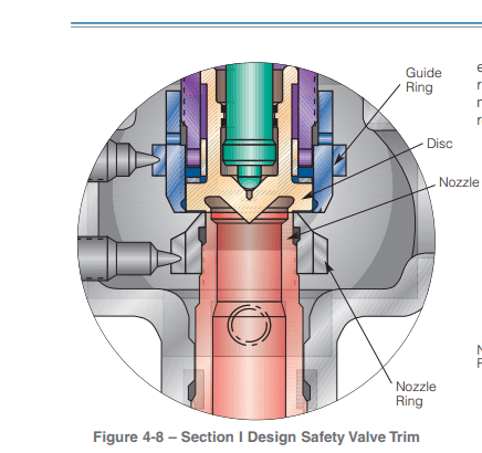
Modern relief valves are wonderfully modular.The internal parts for a relief valve (valve disc,disc holder, blowdown ringandspring) can be interchanged for ones with a different design to customize valve performance based on the application, fluid service, and set pressure.Valve disccan be metal-to-metal or soft seats. Soft seat designs use an elastomer to create a better seal between thevalvediscand thenozzle. Relief valves with elastomer seats have limitations and can only be used in certain applications.Disc holdersare generally designed to allow thevalve discto float which provides an angular movement that reduces seat leakage from minor misalignments (ensuring that thevalve dischas 360 degrees of contact with thenozzle). Thedisc holderoutside diameter, shape and thickness plays an important role in determining the valve performance by defining the shape of thehuddling chamber. Thehuddling chambercan also be defined by theblowdown ring(s). Thering(s)can also be swapped to different sized and shapedringsto adjust performance based on the expected relief fluid.Springsare selected to keep the valve closed and must fit inside thevalve bonnet. The force thespringexerts is an important design criteria for a relief device and varies depending on the relief fluid, valve size and set pressure.
Spring loaded relief valves are known as "pop action" relief valves as they typically pop open at their set pressure. Initially, the pressure differential across thevalve discthat creates the force to over come the spring force and open the valve.The pop action occurs because mosthuddling chambersare designed with an area that is approximately 10%-30% larger than thevalve seat(as thedisc holderis bigger than thevalve disc). Once the pressure under the seat is enough to lift thevalve discoff thenozzle, there is a step change in the upward forces on thespringand the valve "pops" open. The shape of thehuddling chamber(created by the shape and size of thedisc holder), the position and shape of theblowdown ring, and the characteristics of the fluid being relieved together determine the initial opening force and the initial lift of the valve.
Blowdown ringsare adjustable rings with a design shape that modifies the effluent flow path andhuddling chamberbased on the position. For process valves, a singleblowdown ringis typically threaded onto thenozzleand can be adjusted vertically up or down. Manufacturers will specify a recommended position relative to contact with thevalve disc. The position of theblowdown ringis fixed with a locking screw. The position of theblowdown ringchanges the blowdown (or reseat) pressure. For valves with a singleblowdown ring, the closer theblowdown ringis to thenozzle, the lower the pressure in the system will need to be for the valve to close (more blowdown). Other relief valves have multipleblowdown rings. Each manufacturer designs a uniqueblowdown ringto compliment other aspects of the relief valve design. Smith & Burgess" testing confirms that position and design ofblowdown ring(s)affects valve stability.
Relief Valve manufactures generally select aspringthat is designed for the set pressure of the valve. Thespringthat is selected will have a pressure range that thespringcan be applied. In many cases, there may be more than onespringthat can be used with each relief valve each having a different spring constant. The stifferspringmay have a range that is higher than the softerspringbut still meet the overall requirements for set pressure. The selection of thespringwill affect stability as the specific spring influences the natural frequency of the valve and can also affect the blowdown.
%20Cross-Section.png)
As soon as mankind was able to boil water to create steam, the necessity of the safety device became evident. As long as 2000 years ago, the Chinese were using cauldrons with hinged lids to allow (relatively) safer production of steam. At the beginning of the 14th century, chemists used conical plugs and later, compressed springs to act as safety devices on pressurised vessels.
Early in the 19th century, boiler explosions on ships and locomotives frequently resulted from faulty safety devices, which led to the development of the first safety relief valves.
In 1848, Charles Retchie invented the accumulation chamber, which increases the compression surface within the safety valve allowing it to open rapidly within a narrow overpressure margin.
Today, most steam users are compelled by local health and safety regulations to ensure that their plant and processes incorporate safety devices and precautions, which ensure that dangerous conditions are prevented.
The principle type of device used to prevent overpressure in plant is the safety or safety relief valve. The safety valve operates by releasing a volume of fluid from within the plant when a predetermined maximum pressure is reached, thereby reducing the excess pressure in a safe manner. As the safety valve may be the only remaining device to prevent catastrophic failure under overpressure conditions, it is important that any such device is capable of operating at all times and under all possible conditions.
Safety valves should be installed wherever the maximum allowable working pressure (MAWP) of a system or pressure-containing vessel is likely to be exceeded. In steam systems, safety valves are typically used for boiler overpressure protection and other applications such as downstream of pressure reducing controls. Although their primary role is for safety, safety valves are also used in process operations to prevent product damage due to excess pressure. Pressure excess can be generated in a number of different situations, including:
The terms ‘safety valve’ and ‘safety relief valve’ are generic terms to describe many varieties of pressure relief devices that are designed to prevent excessive internal fluid pressure build-up. A wide range of different valves is available for many different applications and performance criteria.
In most national standards, specific definitions are given for the terms associated with safety and safety relief valves. There are several notable differences between the terminology used in the USA and Europe. One of the most important differences is that a valve referred to as a ‘safety valve’ in Europe is referred to as a ‘safety relief valve’ or ‘pressure relief valve’ in the USA. In addition, the term ‘safety valve’ in the USA generally refers specifically to the full-lift type of safety valve used in Europe.
Pressure relief valve- A spring-loaded pressure relief valve which is designed to open to relieve excess pressure and to reclose and prevent the further flow of fluid after normal conditions have been restored. It is characterised by a rapid-opening ‘pop’ action or by opening in a manner generally proportional to the increase in pressure over the opening pressure. It may be used for either compressible or incompressible fluids, depending on design, adjustment, or application.
Safety valves are primarily used with compressible gases and in particular for steam and air services. However, they can also be used for process type applications where they may be needed to protect the plant or to prevent spoilage of the product being processed.
Relief valve - A pressure relief device actuated by inlet static pressure having a gradual lift generally proportional to the increase in pressure over opening pressure.
Relief valves are commonly used in liquid systems, especially for lower capacities and thermal expansion duty. They can also be used on pumped systems as pressure overspill devices.
Safety relief valve - A pressure relief valve characterised by rapid opening or pop action, or by opening in proportion to the increase in pressure over the opening pressure, depending on the application, and which may be used either for liquid or compressible fluid.
In general, the safety relief valve will perform as a safety valve when used in a compressible gas system, but it will open in proportion to the overpressure when used in liquid systems, as would a relief valve.
Safety valve- A valve which automatically, without the assistance of any energy other than that of the fluid concerned, discharges a quantity of the fluid so as to prevent a predetermined safe pressure being exceeded, and which is designed to re-close and prevent further flow of fluid after normal pressure conditions of service have been restored.
In order to ensure that the maximum allowable accumulation pressure of any system or apparatus protected by a safety valve is never exceeded, careful consideration of the safety valve’s position in the system has to be made. As there is such a wide range of applications, there is no absolute rule as to where the valve should be positioned and therefore, every application needs to be treated separately.
A common steam application for a safety valve is to protect process equipment supplied from a pressure reducing station. Two possible arrangements are shown in Figure 9.3.3.
The safety valve can be fitted within the pressure reducing station itself, that is, before the downstream stop valve, as in Figure 9.3.3 (a), or further downstream, nearer the apparatus as in Figure 9.3.3 (b). Fitting the safety valve before the downstream stop valve has the following advantages:
• The safety valve can be tested in-line by shutting down the downstream stop valve without the chance of downstream apparatus being over pressurised, should the safety valve fail under test.
• When setting the PRV under no-load conditions, the operation of the safety valve can be observed, as this condition is most likely to cause ‘simmer’. If this should occur, the PRV pressure can be adjusted to below the safety valve reseat pressure.
• Any additional take-offs downstream are inherently protected. Only apparatus with a lower MAWP requires additional protection. This can have significant cost benefits.
Indeed, a separate safety valve may have to be fitted on the inlet to each downstream piece of apparatus, when the PRV supplies several such pieces of apparatus.
• If supplying one piece of apparatus, which has a MAWP pressure less than the PRV supply pressure, the apparatus must be fitted with a safety valve, preferably close-coupled to its steam inlet connection.
• If a PRV is supplying more than one apparatus and the MAWP of any item is less than the PRV supply pressure, either the PRV station must be fitted with a safety valve set at the lowest possible MAWP of the connected apparatus, or each item of affected apparatus must be fitted with a safety valve.
• The safety valve must be located so that the pressure cannot accumulate in the apparatus viaanother route, for example, from a separate steam line or a bypass line.
It could be argued that every installation deserves special consideration when it comes to safety, but the following applications and situations are a little unusual and worth considering:
• Fire - Any pressure vessel should be protected from overpressure in the event of fire. Although a safety valve mounted for operational protection may also offer protection under fire conditions,such cases require special consideration, which is beyond the scope of this text.
• Exothermic applications - These must be fitted with a safety valve close-coupled to the apparatus steam inlet or the body direct. No alternative applies.
• Safety valves used as warning devices - Sometimes, safety valves are fitted to systems as warning devices. They are not required to relieve fault loads but to warn of pressures increasing above normal working pressures for operational reasons only. In these instances, safety valves are set at the warning pressure and only need to be of minimum size. If there is any danger of systems fitted with such a safety valve exceeding their maximum allowable working pressure, they must be protected by additional safety valves in the usual way.
In order to illustrate the importance of the positioning of a safety valve, consider an automatic pump trap (see Block 14) used to remove condensate from a heating vessel. The automatic pump trap (APT), incorporates a mechanical type pump, which uses the motive force of steam to pump the condensate through the return system. The position of the safety valve will depend on the MAWP of the APT and its required motive inlet pressure.
This arrangement is suitable if the pump-trap motive pressure is less than 1.6 bar g (safety valve set pressure of 2 bar g less 0.3 bar blowdown and a 0.1 bar shut-off margin). Since the MAWP of both the APT and the vessel are greater than the safety valve set pressure, a single safety valve would provide suitable protection for the system.
However, if the pump-trap motive pressure had to be greater than 1.6 bar g, the APT supply would have to be taken from the high pressure side of the PRV, and reduced to a more appropriate pressure, but still less than the 4.5 bar g MAWP of the APT. The arrangement shown in Figure 9.3.5 would be suitable in this situation.
Here, two separate PRV stations are used each with its own safety valve. If the APT internals failed and steam at 4 bar g passed through the APT and into the vessel, safety valve ‘A’ would relieve this pressure and protect the vessel. Safety valve ‘B’ would not lift as the pressure in the APT is still acceptable and below its set pressure.
It should be noted that safety valve ‘A’ is positioned on the downstream side of the temperature control valve; this is done for both safety and operational reasons:
Operation - There is less chance of safety valve ‘A’ simmering during operation in this position,as the pressure is typically lower after the control valve than before it.
Also, note that if the MAWP of the pump-trap were greater than the pressure upstream of PRV ‘A’, it would be permissible to omit safety valve ‘B’ from the system, but safety valve ‘A’ must be sized to take into account the total fault flow through PRV ‘B’ as well as through PRV ‘A’.
A pharmaceutical factory has twelve jacketed pans on the same production floor, all rated with the same MAWP. Where would the safety valve be positioned?
One solution would be to install a safety valve on the inlet to each pan (Figure 9.3.6). In this instance, each safety valve would have to be sized to pass the entire load, in case the PRV failed open whilst the other eleven pans were shut down.
If additional apparatus with a lower MAWP than the pans (for example, a shell and tube heat exchanger) were to be included in the system, it would be necessary to fit an additional safety valve. This safety valve would be set to an appropriate lower set pressure and sized to pass the fault flow through the temperature control valve (see Figure 9.3.8).

www.controlglobal.com is using a security service for protection against online attacks. An action has triggered the service and blocked your request.
Please try again in a few minutes. If the issue persist, please contact the site owner for further assistance. Reference ID IP Address Date and Time 49aa4de84ffe7587c78dee4984bc4222 63.210.148.230 01/29/2023 09:01 AM UTC

Unless you are dealing with a Power Boiler, chances are you have a one ring design safety-relief valve. bill_bill_2000"s commnets were germain to a two ring design Power Boiler Safety Valve. On compressible fluids, the adjusting ring in a one ring design Safety-Relief Valve, must perform three functions. First it needs to be close enough to the disc to direct flow against the disc & disc holder in order to create a reaction force which combines with the inlet force to overcome spring force and cause the valve to pop open. Second, it must be far enough from the disc to allow fluid an escape path so that the valve does not remain open below normal system operating pressure, typically 10% below set pressure. Long blowdown can cause other problems in the system. Thirdly, the ring provides a cushioning effect as the disc reseats. Acting like a retro-rocket, the reaction forces keep the disc from slamming into the nozzle and damaging the seating surfaces.
Blowdown Ring is a specific Part Nomenclature for Farris because it controls reseat. It is referred to as a Nozzle Ring by Crosby for its location (threaded onto the o.d. of the nozzle. Dresser calls it an Adjusting Ring and Knukle refers to it as a Warn Ring. Warn is an older term for simmer. The PRV simmers just prior to pop, therefore simmer is also called warn. SO, 4 major manufacturers with 4 different trems for the same part. The blowdown ring is an important part of PRV Maintenance and Testing. It is what sets PRV repair apart from other mechanical disciplines. DIsassmbly, inspection, machining, lapping and reassembly are common to all valves, pumps, etc. But Blowdown Ring Adjustment is unique to Pressure Relief Valves. Many PRV manufactuerers give ring setting positions in their maintenance manuals. Liquid Settings are typically set very close to the disc during reassembly and require no further adjustment during testing. However, for air/gas/vapor service, the Manufaturers Settings will usually yield long blowdown, because short blowdown may result in insufficient capacity and in a two ring design in chatter. You do not typically see ring setting induced chatter in a one ring design. Most of the time, chatter is a result of an installation problem, i.e. reduced inlet piping, extremely long inlet piping, excessive pressure drop at the PRV inlet. I hope this is helpful
Safety valves, when properly maintained, can last a long time—upwards of 30 years or more. Much more. Recently, a century-old valve arrived at NASVI for repair. After machining and lapping […]
William Rock III, NASVI Valve Disassembler Since 2001 When a valve arrives at our facility for remanufacturing, William Rock III (Bill) is ready and waiting on the front line. He […]
Bronze, steel and stainless steel safety relief valves for air, gas, steam, liquid and vacuum service that meet ASME Section VIII, ‘UV’; Section I, ‘V’, are National Board certified and […]
I cannot tell you how many times in the past few years I’ve been told, “It’s business. It’s not personal.” Another favorite I hear is, “You shouldn’t take things so […]
When it comes to safety valve experience NASVI employees have a mountain of knowledge. Guess how many years of collective experience these three long-time employees have in this short video. […]
Mike Reyes, NASVI Machinist Since 1994 Have you noticed a group of small planes that occasionally fly over Arrowhead on game days and Kansas Speedway on race days? If so, […]
This direct spring-operated pressure relief valve, part of the Series 60 and 80, uses special internals and soft seats for optimum, accurate performance. Of course, we have them in stock. […]
Well, it looks like I didn’t completely bore you readers to tears in the last newsletter, so I’m back for round two. As some lucky people who have recently called […]
The NASVI team goes the extra step in safety valve quality control. Before we ship any valve, we set and test them to the end user’s specifications. This is an […]
Well, it finally happened. The old man, God love him, decided he is no longer writing the “President’s Letter” for our newsletter. After 47 years, apparently, he’s had enough and […]
Q: My customer has a 2-inch line. Do I need to sell them a 2-inch safety valve? A: Safety valves should be sized and selected based on the set pressure […]
Jeff Risner, NASVI Machinist Since 1992 Back in the 1900s (as the younger ones like to call it), Jeff Risner was one of 700 who arrived at Maple Woods Community […]
No doubt you and your customers come face to face with supply chain issues on some level on a daily basis. Manufacturing, warehousing, shipping, trucking, stocking, deliveries and labor shortages […]
Not only is Kunkle’s 6252/6254 among their largest valves, also it’s a very sought-after one. You guessed it; we keep several in stock. For general application, it is suitable for […]
That famous horse racing call by Dave Johnson applies to my pending retirement. I’m down the stretch. I haven’t hit the wire yet, but I haven’t spent a lot of […]
Valve manufacturers are not immune from the supply chain issues plaguing most industries right now. It’s predicted that it will take some time for shipping channels to be adjusted. NASVI […]
Braxton Voss is celebrating his one-year anniversary with NASVI—the “paper” anniversary. What better way to celebrate him than featuring him in our print newsletter? Braxton is an applications engineer who […]
We can’t speak for all Kunkle 218s, but we can account for quite a few of them because they are in our warehouse, ready to ship. Shhhh, don’t tell the […]
With supply chain disruptions hitting manufacturers, it’s important to be proactive as we approach heating season. With 35,000 relief and safety valves in stock & same day shipping, our extensive […]
“Two things you can count on: the earth turning and Andrea getting back [to you] fast, accurately and with tracking. Thank you!” “Your guys just called to tell me this […]
Supply the following information: Example: 1. Quantity of Valves 4 2. Size of Valve Inlet and Outlet 1 ½” x 2” 3. Type, Model or Figure Number 1905FC 4. Manufacturer Consolidated 5. Inlet and […]
If you’re searching for a new Consolidated 1700 Series Maxiflow™ safety valve, or the 2700 and 1900-P1 Series economizer valves, look no further than NASVI. We’re the only company in […]
Did you know that NASVI has 35,000 safety & relief valves ready to ship at a moment’s notice? Or that warehouse is so huge (63,000 square feet!) we have a […]
NASVI pressure tests over 150 valves every day. Watch the process from adjusting the blow down ring to field service guidelines and performing the test pop, to sealing and shipping […]
With every crisis there are winners and losers. Costco, Amazon, Home Depot, Proctor & Gamble, Zoom and others were huge winners while airlines, health clubs, most restaurants, bars, movie theatres, […]
If your customers are requesting a Kunkle liquid relief valve, model 218, then it’ll come as no surprise to you that not all distributors stock them and the manufacturer’s lead […]
No need to wait weeks for order processing and shipping direct from the factory for Anderson Greenwood’s 63B. Why? NASVI has a number of them in stock and ready to […]
We are thrilled to announce that our new website is live. Over the past few months, our team looked for ways to improve your online experience and make getting the […]
A cracked valve, a broken part. There are always unwelcome surprises during a scheduled or unplanned shut down. Operations need to be back up and running ASAP. Don’t wait 7-10 […]
A No Brainer. Wearing face masks and social distancing is a no brainer. It isn’t pleasant, but you do what you have to do. Selling safety valves is also a […]
If you’re on the hunt for a new Consolidated 1700 Series Maxiflow™ safety valve, or the 2700 and P1 Series economizer valves, look no further than NASVI. We’re the only […]
What’s the purpose of a drip pan elbow? It provides a means to handle condensate from safety valves used in steam applications. Where are drip pan elbows used? The drip […]
When you sell safety valves, your customers are under pressure to get what they need fast. That’s why NASVI stocks the largest selection of Kunkle Valves for a variety of […]
Suggest a NASVI Valve Exchange Program. If your customer has several safety valves in need of repair but can’t afford to shut down for lengthy repairs, there’s an easy solution: […]
Offer remanufactured safety valves and watch sales grow. More companies today have found that it makes sense to rely on remanufactured safety valves. For most industrial uses, remanufactured valves offer […]
Five years ago, I wrote that the bean counters were trying to push you around with their slow pay strategies. Because of the virus, the excuses asking for another 30 […]
Offer NASVI’s quick turnaround on repair and testing services. At NASVI, our repair services are designed to keep: Your customer’s safety and relief valves at peak operating efficiency, and Put […]
You don’t have to be an expert in the field of safety and relief valves to sell them because that’s our job. And we’re only a phone call away. We’ll […]
Today, many companies are finding when maintenance budgets need to be stretched; a safe way to save is to rely on remanufactured safety valves. For most industrial uses, remanufactured valves […]
Increase profits, make our new Repair Facility your first stop. North American’s new Service Center is equipped to handle any safety valve repair. NASVI has the specifications for nearly every […]
A.J. Podschwit has an extensive background in industrial sales. In his role as application engineer at North American, he puts it to use every day. “Customers call with specs, but […]
Our goal is to make it easy for you to profit from the sales of safety and relief valves. Call us for assistance. We can help you with sales planning, […]
I am writing this on March 26 and the virus is well into its third week in the United States. We received a letter from Homeland Security that North American […]
Earlier this year, I shared a little product education on safety valves that can make you look really smart to customers, which usually means more orders for everything you sell. […]
When you need something, you go shopping. Choose the wrong place and you can end up wasting a lot of time. Or end up not getting what you need. Costco […]
• More than 35,000 valves in 3,100 varieties • Currently set and ship over 200 valves per day • We repair over 40 valves a week with plenty of capabilities […]
A little product education can make you look super smart to customers, which usually means more orders for everything you sell. Here’s a few things to keep in mind about […]
A popular alternative for customers looking to save money and cut downtime. Today, many companies are finding when maintenance budgets need to be stretched; a safe way to save is […]
Kolby Gabbert has been with North American for nearly a year, and compared to many NASVI employees, he’s still a newcomer. Kolby is an application engineer and enjoys the customer […]
In my 46-year career, I have seen the highs and the lows. The biggest low was the early 80s when double-digit inflation caused prices to go up twice a year […]
Offer North American’s remanufactured safety valves as an alternative and watch your sales grow. Many companies have found that it makes sense to rely on remanufactured safety valves. For most […]
Our repair service center is designed to keep your customer’s safety and relief valves at peak operating efficiency. In addition to an experienced, skilled staff, NASVI’s Service Center is equipped […]
The Taj is looking good, and we’re still making a few adjustments to make it even better. We got a surprise in the mail from the city. They want $1,600 […]
Our giant inventory and remarkable selection awaits your call. One of the customers recently inquired about the availability of five 4-inch liquid flanged valves. The end user had made a […]
Today, many companies are finding when maintenance budgets need to be stretched; a safe way to save is to rely on remanufactured safety valves. For most industrial uses, remanufactured valves […]
Our repair service center is designed to keep your customer’s safety and relief valves at peak operating efficiency. And put extra profits in your pocket. North American’s Service Center is […]
Offer NASVI’s quick turnaround on repair and testing services. At NASVI, our repair services are designed to keep: Your customer’s safety and relief valves at peak operating efficiency, and Put […]
For some reason I get asked pretty frequently if I’m a surgeon. Believe me, you don’t want me operating on you. I tell people I’m the Safety Value Doctor because […]
There’s a fine line between following up with a sales prospect and driving that prospect nuts. By now, you all probably know we’re building a new building. If you have […]
We are moving just a few miles east of our current location. Our plans are to be in place by late summer. When Budgets are Tight, Push the Remanufactured Alternative. […]
Offer NASVI’s quick turn-around on repair and testing services. Over the years, our Service Center has proven popular with maintenance managers. It allows your customer’s plant to have their valves […]
Why Your Sales Team Should Call NASVI 10 EIGHT DEDICATED APPLICATION ENGINEERS. Your coffee won’t get cold waiting for a quick answer to your problem. 9 EXCHANGE & RENTAL PROGRAMS. […]

Safety andRegulating ValvesSAFETY RELIEF VALVESBailey safety relief valves offer a broad spectrum ofprotection against over-pressure for vital services suchas steam, air, gases, water and process fluids.PRESSURE REDUCING VALVESBailey pressure reducing valves offer comprehensivepressure regulation for key services, fire hose andpressure systems using steam, air, water, hot waterand fine industrial gases.SIGHT GLASSESA range of sight glasses are available for visualinspection of key processes.2
The logical choiceWherever demanding applications exist you will findBailey valves, from industrial and commercial todomestic and fire fighting.Bailey valves are used in the construction of hotels,high-rise buildings, hospitals, textile, paper and steelmills, rubber, food, drink, chemical andpharmaceutical processes, off-shore oil and gasplatforms, floating production storage andoff-loading (FPSO) vessels. In fact, anywhere boilers,compressors or pumps produce high-pressureservice media for use on multiple low-pressureapplications.Global legislation covering all pressure equipmentand systems requires regular inspection of plant,pipework and safety provisions. Bailey valves havedemonstrated proven reliability over many yearsand require minimal maintenance.By choosing Bailey, quality, professional advice andproven performance are assured - all deliveredthrough an extensive world-wide network ofdistributors.Should a valve change-out be required at shortnotice, ex-stock availability of most standard valvesvia our extensive distribution network ensuresminimal plant downtime and maximum protection.Experience and focus on customer services makeBailey the logical choice of supplier for valves toreduce or limit pressure in pipework, boilers andvessels - across a wide range of applications.A policy of continuous improvement assures thatBailey valves will always meet current legislativerequirements and of course provide exceptionalreliability and performance. Bailey’s design servicecan help to specify the most appropriate size andtype of valve for any specific application, with theability to include special modifications wherenecessary.3
CONTENTSPageSafety Relief Valves5 Introduction6 Definitions7 Application Table8 Installation Guidelines9-10 70711-12 71613-14 716H15-16 716T17-18 74619-20 75621-22 76623-24 77625-26 480-49027-28 616DPagePressure Reducing Valves29 Introduction and Application Table30 G4 - Pilot Operated Reducing Valve31 Remote Pressure Sensing32 Low Pressure (less than 0.35 Barg)32 Gas and Oxygen Duties33-34 Drawing, Parts List and Materials35 Technical Specification36 Dimensions37-38 Installations39 Setting40 Sizing41 Sizing Example41 Spares42-44 Surplus/Maintaining ValvesPage57-58 1001S Sight GlassPageCapacity Charts/Sizing60-61 Safety Relief ValvesAir Capacity Charts62-63 Safety Relief ValvesSaturated Steam Capacity Charts64-65 Safety Relief ValvesWater Capacity Charts66-67 Safety Relief ValvesHot Water Capacity Charts68 G4 Dry Saturated SteamCapacity Chart69 G4 Air Capacity Charts70-71 G4 Pipe Sizing Chart72-73 C10 and Class T AirCapacity Charts/Sizing74-75 C10 and Class T/TH WaterCapacity Charts/Sizing76 Bailey B Saturated SteamCapacity Charts/Sizing77 Class F SizingPageAssociated ProductsSpring Selection Charts79 480/490 and 707 Spring Selection Charts80 716 Spring Selection Chart81 Pressure Reducing ValvesSpring Selection ChartsDA - Direct Acting Reducing Valves45-46 Class T47-48 Class TH49-50 Bailey B51-52 C1053-54 Class FInstallation55 Installation of PRVs56 Rise to Dead End56 Setting PRVs4
Safety Relief ValvesINTRODUCTIONThe effects of exceeding safe pressure levels in anunprotected pressure vessel or system, can havecatastrophic effects on both plant and personnel.Safety relief valves should be used to protect anypressurised system from the effects of exceeding itsdesign pressure limit.A safety relief valve is designed to automaticallydischarge gas, vapour or liquid from any pressurecontaining system, preventing a predetermined safepressure being exceeded, and protecting plant andpersonnel.Safety ValveA valve which automatically discharges gases andvapours so as to prevent a predetermined safepressure being exceeded. It is characterised by arapid full opening action and is used for steam, gasesor vapour service.Relief ValveA valve which automatically discharges fluid, usuallyliquid, when a predetermined upstream pressure isexceeded. The term is commonly used for pressurerelieving valves in which the lift is proportional tothe increase in pressure above the set pressure.Safety Relief ValveA valve which will automatically discharge gases,vapours or liquids, to prevent a predetermined safepressure being exceeded. It is characterised by arapid opening action.5
DEFINITIONSSet PressureThe pressure measured at the valve inlet at which asafety relief valve should commence to lift underservice conditions.OverpressureThe pressure increase above set pressure at thevalve inlet at which the discharge capacity is attained.Usually expressed as a percentage of set pressure.AccumulationThe pressure increase over a maximum safe workingpressure of the vessel or system when the safetyrelief valve is discharging at its rated capacity iscalled accumulation. The term refers to the vesselor system to be protected and not to the valve.Accumulation is the same as over-pressure when thevalve is set at the design pressure of the vessel.Re-Seat PressureThe pressure measured at the valve inlet at whichthe safety relief valve closes.Blow-DownThe difference between the set pressure and there-seating pressure expressed as a percentage of theset pressure or as a pressure difference.SimmerThe pressure zone between the valve set pressureand the popping pressure. In this pressure zone thevalve is only slightly open and therefore discharging asmall percentage of its rated capacity.Differential Set PressureThis is the difference between the set pressure andthe constant superimposed back pressure. It isapplicable only when a conventional type safety reliefvalve is used to discharge against constantsuperimposed back pressure. (It is the pressure atwhich the safety valve is set at on the test benchwithout back pressure.)Cold Differential Set PressureThe pressure at which a safety relief valve, intendedfor high temperature service, is set on a test rig usinga test fluid at ambient temperature. The colddifferential test pressure will be higher than the setpressure, in order to compensate for the effect ofelevated temperature on the valve. Refer to table onpage 8.Valve LiftThe actual travel of the valve disc away from the seatwhen the valve is relieving.Discharge CapacityActual rate of discharge of service media, which can beexpressed in mass flow or volumetric terms.Equivalent CapacityCalculated mass or volumetric flow rate of the valve ofa given test fluid. The fluids commonly used for testpurposes are steam, air and water.PRESSURE TERM RELATIONSHIPPopping PressureThe pressure at which the valve disc rapidly movesfrom a slightly open (simmer) position to apractically full open position.Superimposed Back PressurePressure higher than atmosphere in the safety reliefvalve outlet. This may result from discharge into thecommon disposal system of other safety relief valvesor devices, or as a result of a specific designrequirement. Back pressure can be either constantor variable depending on the operating conditions.Pressure VesselRequirementMaximumPermittedAccumulationDesignPressureAccumulation% of VesselDesign Pressure11010090Safety ValveCharacteristicOver-pressure(Typical)Blowdown(Typical)MaximumRelievingPressureSetPressureRe-seatPressureBuilt Up Back PressureThe pressure existing at the outlet of a safety reliefvalve caused by flow through the valve into thedisposal system.Note: System operating pressure must always be less than there-seat pressure.6
INSTALLATIONSafety Relief Valves should always be installed in anupright position with their spring chamber vertical.All packing materials should be removed from thevalve connections prior to installation.Pressure VesselsWhen fitting a Safety Relief Valve onto pressurevessels, the inlet connection pipe should be as shortas possible and the bore should be at least equivalentto the nominal bore size of the valve.The pressure drop between the vessel and the valveshould be no more than 3% at rated capacity.A pressure-tight dome should be specified when:1) A back pressure must be contained within therelieving system.2) A head of liquid is built up within the valve bodyand consequently needs to be contained.3) The relieving medium is toxic, corrosive orenvironmentally unfriendly.PipelinesWhen fitting a Safety Relief Valve into a pipeline, theinlet connecting pipe leading from the main pipeline tothe Safety Relief Valve should be as short as possible,so that the inlet pressure drop is no more than 3% ofrated capacity.In addition, it is advised that the Safety Relief Valve isplaced a sufficient distance downstream of thepressure source. This will protect the valve from theadverse effects of pressure pulsations.Discharge PipelinesThese should be equal to or larger than the valveoutlet, with adequate supports, minimum number ofbends and overall length. Unless balanced bellowsvalves are installed, the maximum built upbackpressure should not exceed 10% of the setpressure, although the 746, 756 and the 766 canhandle higher back pressure if required. Steamservice valves should be adequately drained.Alignment of the discharge or drain should present norisk to persons or property. Protection from thecollection of rainwater or condensation in thedischarge pipe is advisable.System CleansingIt is essential that new installations are fully flushed andall debris removed prior to installing the valve asserious damage can be caused to valve seats, resultingin subsequent leakage.Pressure AdjustmentEvery valve is fitted with a suitable spring and testedbefore leaving the factory. Valves can be preset onrequest but to alter the set pressure, the adjustingscrew, when viewed from the top, should be screweddownwards in a clockwise direction to increase theset pressure and upwards in an anti-clockwisedirection to decrease it. Set pressure adjustment mustbe carried out by experienced and approvedpersonnel. Any change in set pressure must be withinthe range of the existing spring, if it exceeds the range,a new spring will be required. The cap lead seal mustbe re-made after any adjustment to the set pressure.Blowdown Adjustment(756 & 766 valves only)The blowdown ring (part no. 8) is set before the valveleaves the factory and normally no further adjustmentwill be necessary. However, if the reseating pressurehas to be altered in service, the blowdown ring shouldbe screwed (downwards) clockwise to raise there-seat, popping and simmer pressures. If theblowdown ring is screwed (upwards) anti-clockwisethe re-seat, popping and simmer pressures will lower.When re-inserting the setting screw (part no 9.) itshould always be placed to engage a slot in theblowdown ring. The standard blowdown is 5% for756 and 10% for 766 valves (minimum 0.3 Barg forboth valve types).For recommended settings, please contact ourtechnical sales office who will be pleased to help.COLD DIFFERENTIAL TEST PRESSUREWhen setting a valve intended for use at hightemperature on a test rig using a test fluid at ambienttemperatures, it is necessary to set the valve at aslightly higher pressure, so that it will open at thecorrect set pressure under operating conditions. Thenecessary allowance is shown in the following table.OperatingtemperatureIncrease in setpressure at ambienttemperatureUp to 121°CNone122°C to 316°C 1%317°C to 427°C 2%8
707 Safety Relief ValveDESIGNThe Bailey 707 Safety Relief Valve encompasses a topguided design, combining an unobstructed seat borewith high lift capability. This bronze bodied valve canbe supplied with a resilient or metal trim with achoice of screwed and flanged connections.The Bailey 707 is certified to BS EN 4126 Part 1(BS6759 pt 1:2:3) and is suitable for duty on air/gas,steam/hot water (above 100ºC) and process liquid.Test levers are available for inline safety checking,alternatively a sealed dome can be supplied for serviceconditions requiring a pressure tight seal on thedischarge side, eg. liquid service with encloseddischarge.TECHNICAL SPECIFICATIONApprovalsBS EN ISO 4126 Part 1 (SAFED)Pressure Equipment Directive (PED)ISO 9001:2008Water Regulation Advisory Scheme (WRAS)MaterialsBody - Bronze from -20 to 224°CTrim - St.St/EPDM from -20 to 95°C- St.St/Aflas from -20 to 200°C- St.St. from -20 to 224°CSize RangeOrifice Min (Barg) Max (Barg)Size mm 2 Pressure PressureDN15 ( 1 ⁄2") 126 0.3 24.0DN20 ( 3 ⁄4") 364 0.3 24.0DN25 (1") 481 0.3 24.0DN32 (1 1 ⁄4") 791 0.3 24.0DN40 (1 1 ⁄2") 1240 0.3 24.0DN50 (2") 1943 0.3 24.0PerformanceOver BlowKdr pressure downSteam 0.173 10% 15%*Hot water‡ 0.173 10% 15%*Air / Gas 0.173 10% 15%*Liquid 0.149 10% 20%*†* or 0.3 Barg min † or 0.6 Barg min ‡ above 100°CMaximum Back PressureBarg 5.5Constant 80%Built-up 10%Variable 0%(Total % must not exceed Barg shown)ConnectionsScrewed Female In x Screwed Female OutScrewed Male In x Screwed Female OutFlanged In x Flanged OutConstructionTop Guided / High LiftCap OptionsOpen leverScrew-on pressure tight domeSizingRefer to Capacity Charts (page 60-67)Spring SelectionRefer to Spring Selection Chart (page 79)9
SIZINGTemperature Rating in kWSize 3⁄4" 1" 1 1 ⁄4" 1 1 ⁄2" 2"kW 44 70 80 173 184kW (Per BSEN 1490) 25 50 75 100 -To convert kW to Btu/hr multiply by 3400. The temperature probe will safely open therelief valve approximately in the region of 90 to 95°C.Pressure Rating in kWSet PSizeBarg 3⁄4" 1" 1 1 ⁄4" 1 1 ⁄2" 2"2.4 166 186 315 524 6312.5 171 192 324 540 6503.0 196 220 371 619 7454.0 246 277 466 777 9355.0 296 323 560 935 11256.0 345 389 655 1093 13157.0 395 445 749 1251 15058.0 445 502 844 1409 16959.0 495 558 939 1567 188510.0 545 614 1033 1725 207510.3 560 631 1062 1773 2132The kW rating shown has been calculated in accordance with BS6759 pt1 and ASME IV.They represent the steam relief capacity of the relief valve at 10% over pressure.To convert kW to Btu/hr multiply by 3400.DIMENSIONSInlet & Outlet A B C D (kg)BSP3⁄4" male x 3 ⁄4" female 38 62 262 113 0.601" male x 1" female 40 53 262 121 0.751 1 ⁄4" male x 1" female* 44 50 259 99 1.201 1 ⁄2" male x 1 1 ⁄2" female 63 68 271 80 2.002" male x 2" female 63 75 280 65 2.00CB*1 1 ⁄4" valve has a 1" outlet All dimensions in mmDA16
746 Safety Relief ValveDESIGNThe 746 Safety Relief Valve incorporates a freelypivoting disc, which ensures correct alignment withthe nozzle. The combination of top guiding,unobstructed seat bore and full lift capability ensuresthe highest possible discharge rate thus maximumplant protection.Due to the large flows available the inlet pipeworkmust be sized to give a maximum inlet pressure dropof 3%The 746 safety relief valve is available in bothconventional and balanced bellows types, and featuresa special disc style for liquid application, whichenhances valve performance.The ‘conventional’ arrangement is suitable forapplications where the built up pressure will notexceed 5%. The conventional valve can also be usedin systems where the superimposed backpressure is ata constant level (up to 80%).The ‘balanced bellows’ arrangement is for applicationswhere several safety relief valves discharge into acommon discharge manifold, or in any circumstanceswhere a variable back pressure can occur, up to amaximum of 40%.TECHNICAL SPECIFICATIONApprovalsBS6759 Pt 1, 2, & 3ASME VIIITUV-AD Merkblatt A2PED certified Category IVMaterialsBody - Carbon St. gr WCB (-29 to 427°C)- Stainless St. gr CF8M (-46 to 427°C)Trim - Stainless Steel (-46 to 427°C)- Viton (-29 to 200°C)- PTFE (-46 to 220°C)- EPDM - Hot Water (-29 to 150°C)Size RangeOrifice Min (Barg) Max (Barg)Size mm 2 Pressure* PressureDN25 (1") 415 0.35 40DN32 (1 1 ⁄4") 660 0.35 40DN40 (1 1 ⁄2") 1075 0.35 40DN50 (2") 1662 0.35 40DN65 (2 1 ⁄2") 2827 0.35 35DN80 (3") 4301 0.35 32DN100 (4") 6648 0.35 25* Minimum pressure for bellows valves is greater than statedPerformance (BS6759)Over BlowKdr pressure downSteam 0.7 5% 15%*Hot water‡ 0.7 5% 15%*Air / Gas 0.7 10% 10%*Liquid 0.46 10% 20%†*or 0.3 Barg min †or 0.6 Barg min ‡above 100°CPerformance (ASME)Over BlowKdr pressure downSteam 0.738 10% FixedAir / Gas 0.738 10% FixedLiquids 0.482 10% FixedMaximum Back PressureBarg 16Constant 80%Built-up 5%Variable 40% (when bellows fitted)(Total % must not exceed Barg shown)ConnectionsFlanged In x Flanged OutConstructionTop Guided / Full LiftCap OptionsPressure tight domePacked leverOpen leverSizingRefer to Capacity Charts (page 60-67)17
PARTSITEM PART MATERIALSCarbon SteelSt.St69181992731547731328121134332211DIMENSIONSFlanged x Flanged4121047238142621Lever versionsare available.1 Body Carbon St St.St2 Bonnet Carbon St. St.St3 Cap Carbon St. St.St4 Seat St.St St.St5* Disc# St.St St.St9 Guide Plate St.St St.St10 (H) Spindle St.St St.St11 Spring Plate St.St St.St12 Adjusting Screw St.St St.St13 Locknut St.St St.St18 (H) Body Stud Carbon St St.St19 Body Nut Carbon St St.St22 (H) Spring** C.V St.St23 (B)* Bellows Unit St.St St.St27* Body/Bonnet Gasket Garlock Garlock28* Cap Gasket Garlock Garlock31* Ball St.St St.St33 Nameplate St.St St.St34 Nameplate Pin Carbon St St.St41 Warranty Seal Lead/wire Lead/wire42 Drain Plug Carbon St St.St47(BH) Spacing Piece St.St St.St62 Seat Pin St.St St.St69 Split Collar St.St St.St77 Adjusting Screw Bush PTFE PTFE81(B) Lift Stop St.St St.StNote:B - Denotes used on Bellows type valves.H - High Pressure type valves; spacer, larger studs, spring andspindle.# Resilient trims are available.* Recommended spares; available from Safety Systems UK Ltd.** Other spring material options are available dependent on duty.Recommended inspection every 12 months.FIGURE NUMBERINGC746 /FlangedADValve Valve Inlet Outlet ‘C’ ‘C’ ‘C’ WeightType Size A Dome Lever Bellows D (kg)DN25 1" 1 1 ⁄2" 105 410 410 445 100 8.5DN32 1 1 ⁄4" 2" 115 455 455 490 110 14.0DN40 1 1 ⁄2" 2 1 ⁄2" 140 570 570 605 115 20.0DN50 2" 3" 150 615 615 665 120 30.0DN65 2 1 ⁄2" 4" 170 725 725 785 140 42.5DN80 3" 5" 195 825/ 825/ 865/ 160 64.5925H 925H 965H925/ 925/ 955/DN100 4" 6" 220 1030 1030 1060 180 86.0H HFlange sizes listed are for:Carbon Steel Flanges PN 40x16Others available on request.All dimensions in mmTYPE1. Conventional2. Bellows3. Liquid Conventional4. Liquid BellowsSIZE1. 25 x 40mm2. 32 x 50mm3. 40 x 65mm4. 50 x 80mm5. 65 x 100mm6. 80 x 125mm7. 100 x 150mmCONNECTIONS1. PN 16 RF x PN 16 RF2. PN 40 RF x PN 16 RF5. ANSI 150 RF x 150 RF6. ANSI 300 RF x 150 RFNotes:A. Any special requirements will beindicated by the letter X which will beagreed with the sales office. For example,paint specification or spring material.B. Any combination of features can be calledup eg. DG, PR, DFRN etc.C. (H) for ‘746’ 80 and 100mm valves only.BODY MATERIAL2. Carbon Steel3. Stainless SteelFEATURESD. Domed CapF. FerruleG. GagM. Open LeverN. NACE MaterialsP. Packed LeverR. Resilient SeatH. High Pressure (H)X. Special Details18
756 Safety Relief ValveDESIGNThe 756 Safety Valve combines a top piston guidedvalve and an unobstructed seat bore with a full liftcapability, giving maximum discharge capacity. Thedesign incorporates an adjustable blowdown ring andmeets all the requirements of BS6759 Part 1.A freely pivoting disc and precision lapped stainlesssteel trim gives positive re-seating for steam duty. Asstandard the 756 is fitted with a test lever for inlinetesting. Ideally suited to applications on steam boilersand pipelines where blowdown tolerances are critical.TECHNICAL SPECIFICATIONApprovalsBS6759 Pt 1PED certified Category IVMaterialsBody - Carbon St. gr WCB (-29 to 300°C)Trim - Stainless SteelSize RangeOrifice Min (Barg) Max (Barg)Size mm 2 Pressure PressureDN25 (1") 415 0.35 24DN32 (1 1 ⁄4") 660 0.35 24DN40 (1 1 ⁄2") 1075 0.35 24DN50 (2") 1662 0.35 24DN65 (2 1 ⁄2") 2827 0.35 24DN80 (3") 4301 0.35 24PerformanceOver BlowKdr pressure downSteam 0.716 5% 5%**or 0.3 Barg minMaximum Back PressureBarg 12Constant 0%Built-up 50%Variable 0%(Total % must not exceed Barg shown)ConnectionsFlanged In x Flanged OutConstructionTop Guided / Full LiftCap OptionsOpen lever fitted as standardSizingRefer to Capacity Charts (page 60-67)19
PARTSITEM PART MATERIALCarbon Steel2932302832614312131217212215 161There are twovent holes toensure springchamber is atatmosphericpressure.411125101218205897232441 Body Carbon Steel2 Bonnet Carbon Steel3 Cap Carbon Steel4 Seat St.St.5* Disc St.St.7* Set Screw Gasket NAF8 Blowdown Ring St.St.9 Setting Screw Brass10 Guide Plate Bronze11 Spindle St.St.12 Spring Plate Brass13 Adjusting Screw Brass14 Locknut Brass15 Body Stud Carbon Steel16 Body Nut Carbon Steel17* Spring Chrome Vanadium18* Body/Bonnet Gasket NAF20* Ball St.St.21 Nameplate St.St.22 Nameplate Pin Steel23 Drain Plug Steel24 Seat Pin St.St.25* Split Collar St.St.26 Adjusting Screw Bush PTFE28 Fulcrum Pin St.St.29 Spindle nut Brass30 Easing Lever Carbon Steel31 Grub Screw St.St.32 Spindle Washer St.St.41 Warranty Seal Lead* Recommended spares; available from Safety Systems UK Ltd.Recommended inspection every 12 months.DIMENSIONSFIGURE NUMBERINGFlanged x Flanged756FlangedADValve Valve Inlet Outlet ‘C’ WeightType Size *NB *NB A Lever D (kg)CDN25 1" 1 1 ⁄2" 105 410 100 8.5DN32 1 1 ⁄4" 2" 115 455 110 14.0DN40 1 1 ⁄2" 2 1 ⁄2" 140 570 115 20.0DN50 2" 3" 150 615 120 30.0DN65 2 1 ⁄2" 4" 170 725 140 42.5DN80 3" 5" 195 825* 160 64.5TYPE1. ConventionalSIZE1. 25 x 40mm2. 32 x 50mm3. 40 x 65mm4. 50 x 80mm5. 65 x 100mm6. 80 x 125mmCONNECTIONS1. PN 16 RF x PN 16 RF2. PN 40 RF x PN 16 RF5. ANSI 150 RF x 150 RF6. ANSI 300 RF x 150 RFBODY MATERIAL2. Carbon SteelNotes:A. Any special requirements will be indicated by the letter X whichwill be agreed with the sales office. For example, paintspecification or spring material.FEATURESG. GagM. Open Lever*Add 100mm to the DN80 Fig. 756 valveonly for set pressures above 14 Barg.All dimensions in mmFlange sizes listed are for:Carbon Steel Flanges PN 40x16Others available on request.20
766 Safety Relief ValveDESIGNThe 766 Safety Valve is a double spring high lift valvewith high discharge capacity. The top guided pistondesign incorporates an adjustable blowdown ring andmeets all the requirements of BS6759 Part 1.A freely pivoting disc and precision lapped stainlesssteel trim gives positive re-seating for steam duty.Fitted as standard with test lever for inline testing.Ideally suited to applications on steam boilers andpipelines where blowdown tolerances are critical.TECHNICAL SPECIFICATIONApprovalsBS6759 Pt 1PED certified Category IVMaterialsBody - Carbon St. gr WCB (-29 to 230°C)Trim - Stainless Steel (-29 to 230°C)Size RangeOrifice Min (Barg) Max (Barg)Size mm 2 Pressure PressureDN40 (1 1 ⁄2") 2280 0.35 24DN50 (2") 4054 0.35 24DN65 (2 1 ⁄2") 6334 0.35 24DN80 (3") 9121 0.35 24PerformanceOver BlowKdr pressure downSteam 0.4 10% 10%**or 0.3 Barg minMaximum Back PressureBarg CS 12 / CI 6Constant 0%Built-up 50%Variable 0%(Total % must not exceed Barg shown)ConnectionsFlanged In x Flanged OutConstructionTop Guided / High LiftCap OptionsOpen lever fitted as standardSizingRefer to Capacity Charts (page 60-67)FIGURE NUMBERING766TYPE1. ConventionalVALVE SIZE*†3. 40mm (2 1 ⁄2" x 3")4. 50mm (3" x 4")5. 65mm (4" x 5")6. 80mm (4" x 6")CONNECTIONS1. PN 16 RF x PN 16 RF2. PN 40 RF x PN 16 RF5. ANSI 150 RF x 150 RF6. ANSI 300 RF x 150 RFFEATURESG. GagM. Open LeverBODY MATERIAL2. Carbon Steel21*Flange sizes are larger than the valve size, refer to the dimension tableNotes:A. Any special requirements will be indicated by the letter X which will be agreedwith the sales office. For example, paint specification or spring material.B. Any combination of features can be called up eg. MG etc.C. Flange options are dependant on Valve Body materials, as detailed opposite.† Please see table on page 22 for inlet and outlet connection sizes.
PARTSITEM PART MATERIALThere are twovent holes toensure springchamber is atatmosphericpressure.22253016181514171312271121610 320498511 Body Carbon Steel2 Cover Carbon Steel3 Valve Disc Holder Bronze4* Valve Disc St.St.5 Seat Ring St.St.6 Guide Bronze7 Spindle St.St8 Blow Down Ring St.St9 Setting Screw St.St10* Valve Disc Ball St.St11* Spindle Ball St.St12* Spring Chrome Vanadium13 Easing Lever SG Iron14 Dome Bronze15 Dome Cap Carbon Steel16 Adjusting Screw Brass17 Locknut Brass18 Spring plate Plated Steel20* Disc Retaining Clip St.St21* Body Gasket Garlock22 Locking Pin Brass23 Seat Securing Pin St.St25 Padlock Brass26 Body Stud Steel27 Body Stud Nut Steel28 Nameplate St.St29 Nameplate screw Steel30 Locknut SteelNote:* Recommended spares; available from Safety Systems UK Ltd.Recommended inspection every 12 months.282926DIMENSIONS27Flanged x Flanged23Valve Valve Inlet† Outlet† A B C D E F (BSP) K WeightType Size CS CS CS DRAIN CS (kg)FlangedDN40 2 1 ⁄2" 3" 197 22 452 156 185 3⁄8" 200 25DN50 3" 4" 229 24 498 181 200 1⁄2" 220 38DN65 4" 5" 279 24 660 219 235 1⁄2" 250 58DN80 4" 6" 295 24 702 238 235 1⁄2" 285 83Flange sizes listed are for:Carbon Steel Flanges PN 40x16Others available on request.All dimensions in mm.22
776 Cryogenic Safety ValveDESIGNThe 776 Safety Relief Valve is designed for cryogenicduty down to -196°C. The valve combines a full liftdesign and top guided construction with anunobstructed seat bore to provide maximum dischargecapacity. Positive sealing is achieved through a freelypivoted disc with Kel F (PCTFE) soft seat technology.The valve is designed to conform with ISO4126,AD Merkblatt A2, ASME VIII and BS6759 Parts 2 & 3.Production assembly and tests are carried out inaccordance with both BOC and Air Productsspecifications.BOC specification: 1819660 and 399856.Air Products specification: 4WPI-EW80010, and4WPI-SW70003.TECHNICAL SPECIFICATIONApprovalsAD Merkblatt A2ASME VIIIBS 6759 Pt. 2 & 3PED certified Category IVMaterialsBody - Bronze (-196 to 60°C)- Stainless steel (-268 to 60°C)Trim - Kel F PCTFE (-268 to 60°C)Size RangeSize Orifice Min (Barg) Max (Barg)(Orifice code) mm 2 Pressure PressureDN15 (1 & 2M) 109 1 41.3DN20 (2R) 109 1 41.3DN20 (2 & 2M1) 109 1 41.3DN20 (3) 314 1 38.6DN25 (4) 314 1 38.6DN32 (5) 415 1 34.5DN40 (6) 660 1 34.5DN50 (7) 1075 1 31Coefficient of DischargeAir(TUV alpha W) Above Above Above Above AboveOrifice codes 3 Barg 2.5 Barg 2 Barg 1.5 Barg 1 Barg1, 2, 4, 5, 6, 7 0.69 0.69 0.69 0.67 0.633 0.67 0.65 0.63 0.62 0.581R, 2R 0.40 0.40 0.40 0.39 0.36Air (ASME Kdr) 0.737PerformanceOver Pressure 10% Blowdown 10%Maximum Back PressureBarg 5.5Constant 80%Built-up 10%Variable 0%(Total % must not exceed Barg shown)ConnectionsScrewed In x Screwed OutConstructionTop Guided / Full LiftCap OptionsPressure tight dome fitted as standardSizingRefer to Capacity Charts (page 60-67)23
PARTS1418121611101978613317152ITEM PART MATERIAL1 Body Bronze2 Seat Bronze3* Disc Assembly St.St. / Kel F PCTFE6 Guide Bronze7 Lower Spring Plate Brass8 Spindle Brass9* Spring St.St10 Upper Spring Plate Brass11 Adjusting Screw Brass12 Locknut Brass13* Ball St.St14 Cap Brass15* Body Gasket Gylon PTFE16* Cap Gasket Gylon PTFE17 Grubscrew St.St18 Bush PTFENote:* Recommended spares; available from Safety Systems UK Ltd.Refer to factory for Stainless Steel version.Recommended inspection every 12 months.DIMENSIONSFIGURE NUMBERINGFig. Size Trim ConnectionsMale x FemaleADValve Valve Inlet Outlet ‘C’ WeightType Size *BSP *BSP A Dome D (kg)CDN15 /1 1⁄2" 3⁄4" 52 173 40 1.0DN15 /1R 1⁄2" 3⁄4" 52 173 40 1.0DN15 /2M 1⁄2" 1" 52 173 45 1.0DN20 /2R 3⁄4" 1" 70 191 45 1.0DN20 /2 3⁄4" 1" 70 191 45 1.0DN20 /3 3⁄4" 1 1 ⁄4" 63 231 55 1.6DN25 /2M1 1" 1" 70 191 45 1.0DN25 /4 1" 1 1 ⁄4" 73 241 55


 8613371530291