
blowdown ring in safety valve free sample
www.controlglobal.com is using a security service for protection against online attacks. An action has triggered the service and blocked your request.
Please try again in a few minutes. If the issue persist, please contact the site owner for further assistance. Reference ID IP Address Date and Time 49aa4de84ffe7587c78dee4984bc4222 63.210.148.230 01/29/2023 09:01 AM UTC

In order to ensure that the maximum allowable accumulation pressure of any system or apparatus protected by a safety valve is never exceeded, careful consideration of the safety valve’s position in the system has to be made. As there is such a wide range of applications, there is no absolute rule as to where the valve should be positioned and therefore, every application needs to be treated separately.
A common steam application for a safety valve is to protect process equipment supplied from a pressure reducing station. Two possible arrangements are shown in Figure 9.3.3.
The safety valve can be fitted within the pressure reducing station itself, that is, before the downstream stop valve, as in Figure 9.3.3 (a), or further downstream, nearer the apparatus as in Figure 9.3.3 (b). Fitting the safety valve before the downstream stop valve has the following advantages:
• The safety valve can be tested in-line by shutting down the downstream stop valve without the chance of downstream apparatus being over pressurised, should the safety valve fail under test.
• When setting the PRV under no-load conditions, the operation of the safety valve can be observed, as this condition is most likely to cause ‘simmer’. If this should occur, the PRV pressure can be adjusted to below the safety valve reseat pressure.
• Any additional take-offs downstream are inherently protected. Only apparatus with a lower MAWP requires additional protection. This can have significant cost benefits.
Indeed, a separate safety valve may have to be fitted on the inlet to each downstream piece of apparatus, when the PRV supplies several such pieces of apparatus.
• If supplying one piece of apparatus, which has a MAWP pressure less than the PRV supply pressure, the apparatus must be fitted with a safety valve, preferably close-coupled to its steam inlet connection.
• If a PRV is supplying more than one apparatus and the MAWP of any item is less than the PRV supply pressure, either the PRV station must be fitted with a safety valve set at the lowest possible MAWP of the connected apparatus, or each item of affected apparatus must be fitted with a safety valve.
• The safety valve must be located so that the pressure cannot accumulate in the apparatus viaanother route, for example, from a separate steam line or a bypass line.
It could be argued that every installation deserves special consideration when it comes to safety, but the following applications and situations are a little unusual and worth considering:
• Fire - Any pressure vessel should be protected from overpressure in the event of fire. Although a safety valve mounted for operational protection may also offer protection under fire conditions,such cases require special consideration, which is beyond the scope of this text.
• Exothermic applications - These must be fitted with a safety valve close-coupled to the apparatus steam inlet or the body direct. No alternative applies.
• Safety valves used as warning devices - Sometimes, safety valves are fitted to systems as warning devices. They are not required to relieve fault loads but to warn of pressures increasing above normal working pressures for operational reasons only. In these instances, safety valves are set at the warning pressure and only need to be of minimum size. If there is any danger of systems fitted with such a safety valve exceeding their maximum allowable working pressure, they must be protected by additional safety valves in the usual way.
In order to illustrate the importance of the positioning of a safety valve, consider an automatic pump trap (see Block 14) used to remove condensate from a heating vessel. The automatic pump trap (APT), incorporates a mechanical type pump, which uses the motive force of steam to pump the condensate through the return system. The position of the safety valve will depend on the MAWP of the APT and its required motive inlet pressure.
This arrangement is suitable if the pump-trap motive pressure is less than 1.6 bar g (safety valve set pressure of 2 bar g less 0.3 bar blowdown and a 0.1 bar shut-off margin). Since the MAWP of both the APT and the vessel are greater than the safety valve set pressure, a single safety valve would provide suitable protection for the system.
However, if the pump-trap motive pressure had to be greater than 1.6 bar g, the APT supply would have to be taken from the high pressure side of the PRV, and reduced to a more appropriate pressure, but still less than the 4.5 bar g MAWP of the APT. The arrangement shown in Figure 9.3.5 would be suitable in this situation.
Here, two separate PRV stations are used each with its own safety valve. If the APT internals failed and steam at 4 bar g passed through the APT and into the vessel, safety valve ‘A’ would relieve this pressure and protect the vessel. Safety valve ‘B’ would not lift as the pressure in the APT is still acceptable and below its set pressure.
It should be noted that safety valve ‘A’ is positioned on the downstream side of the temperature control valve; this is done for both safety and operational reasons:
Operation - There is less chance of safety valve ‘A’ simmering during operation in this position,as the pressure is typically lower after the control valve than before it.
Also, note that if the MAWP of the pump-trap were greater than the pressure upstream of PRV ‘A’, it would be permissible to omit safety valve ‘B’ from the system, but safety valve ‘A’ must be sized to take into account the total fault flow through PRV ‘B’ as well as through PRV ‘A’.
A pharmaceutical factory has twelve jacketed pans on the same production floor, all rated with the same MAWP. Where would the safety valve be positioned?
One solution would be to install a safety valve on the inlet to each pan (Figure 9.3.6). In this instance, each safety valve would have to be sized to pass the entire load, in case the PRV failed open whilst the other eleven pans were shut down.
If additional apparatus with a lower MAWP than the pans (for example, a shell and tube heat exchanger) were to be included in the system, it would be necessary to fit an additional safety valve. This safety valve would be set to an appropriate lower set pressure and sized to pass the fault flow through the temperature control valve (see Figure 9.3.8).

(a) The inlet opening shall have an inside diameter approximately equal to, or greater than, the seat diameter. In no case shall the maximum opening through any part of the valve be less than ¼ in. (6 mm) in diameter or its equivalent area.
(c) O-rings or other packing devices when used on the stems of safety relief valves shall be so arranged as not to affect their operation or capacity.
(d) The design shall incorporate guiding arrangements necessary to insure consistent operation and tightness. Excessive lengths of guiding surfaces should be avoided. Bottom guided designs are not permitted on safety relief valves.
(f) Safety valves shall be spring loaded. The spring shall be designed so that the full lift spring compression shall be no greater than 80% of the nominal solid deflection. The permanent set of the spring (defined as the difference between the free height and height measured 10 min after the spring has been compressed solid three additional times after presetting at room temperature) shall not exceed 0.5% of the free height.
(g) There shall be a lifting device and a mechanical connection between the lifting device and the disk capable of lifting the disk from the seat a distance of at least 1/16 in. (1.5 mm) with no pressure on the boiler.
(h) A body drain below seat level shall be provided by the Manufacturer for all safety valves and safety relief valves, except that the body drain may be omitted when the valve seat is above the bottom of the inside diameter of the discharge piping. For valves exceeding NPS 2½ (DN 65) the drain hole or holes shall be tapped not less than NPS 3/8 (DN 10). For valves NPS 2½ (DN 65) or smaller, the drain hole shall not be less than ¼ in. (6 mm) in diameter. Body drain connections shall not be plugged during or after field installation. In safety relief valves of the diaphragm type, the space above the diaphragm shall be vented to prevent a buildup of pressure above the diaphragm. Safety relief valves of the diaphragm type shall be so designed that failure or deterioration of the diaphragm material will not impair the ability of the valve to relieve at the rated capacity.
(k) The set pressure tolerances, plus or minus, of safety valves shall not exceed 2 psi (15 kPa), and for safety relief valves shall not exceed 3 psi (20 kPa) for pressures up to and including 60 psig (400 kPa) and 5% for pressures above 60 psig (400 kPa).
(l) Safety valves shall be arranged so that they cannot be reset to relieve at a higher pressure than the maximum allowable working pressure of the boiler.
(e) Material for valve bodies and bonnets or their corresponding metallic pressure containing parts shall be listed in Section II,except that in cases where a manufacturer desires to make use of materials other than those listed in Section II, he shall establish and maintain specifications requiring equivalent control of chemical and physical properties and quality.
(g) No materials liable to fail due to deterioration or vulcanization when subjected to saturated steam temperature corresponding to capacity test pressure shall be used.
(a) A Manufacturer shall demonstrate to the satisfaction of an ASME designee that his manufacturing, production, and testing facilities and quality control procedures will insure close agreement between the performance of random production samples and the performance of those valves submitted for capacity certification.
(c) A Manufacturer may be granted permission to apply, the HV Code Symbol to production pressure relief valves capacity certified in accordance with HG-402.3 provided the following tests are successfully completed. This permission shall expire on the sixth anniversary of the date it is initially granted. The permission may be extended for 6 year periods if the following tests are successfully repeated within the 6 month period before expiration.
(1) Two sample production pressure relief valves of a size and capacity within the capability of an ASME accepted laboratory shall be selected by an ASME designee.
(2) Operational and capacity tests shall be conducted in the presence of an ASME designee at an ASME accepted laboratory. The valve Manufacturer shall be notified of the time of the test and may have representatives present to witness the test.
(3) Should any valve fail to relieve at or above its certified capacity or should it fail to meet performance requirements of this Section, the test shall be repeated at the rate of two replacement valves, selected in accordance with HG-401.3(c)(1), for each valve that failed.
(4) Failure of any of the replacement valves to meet the capacity or the performance requirements of this Section shall be cause for revocation within 60 days of the authorization to use the Code Symbol on that particular type of valve. During this period, the Manufacturer shall demonstrate the cause of such deficiency and the action taken to guard against future occurrence, and the requirements of HG-401.3(c) above shall apply.
(d) Safety valves shall be sealed in a manner to prevent the valve from being taken apart without breaking the seal. Safety relief valves shall be set and sealed so that they cannot be reset without breaking the seal.
(a) Every safety valve shall be tested to demonstrate its popping point, blowdown, and tightness. Every safety relief valve shall be tested to demonstrate its opening point and tightness. Safety valves shall be tested on steam or air and safety relief valves on water, steam, or air. When the blowdown is nonadjustable, the blowdown test may be performed on a sampling basis.
(c) Testing time on safety valves shall be sufficient, depending on size and design, to insure that test results are repeatable and representative of field performance.
HG-401.5 Design Requirements. At the time of the submission of valves for capacity certification, or testing in accordance with this Section, the ASME Designee has the authority to review the design for conformity with the requirements of this Section, and to reject or require modification of designs that do not conform, prior to capacity testing.
HG-402.1 Valve Markings. Each safety or safety-relief valve shall be plainly marked with the required data by the Manufacturer in such a way that the markings will not be obliterated in service. The markings shall be stamped, etched, impressed, or cast on the valve or on a nameplate, which shall be securely fastened to the valve.
(6) year built or, alternatively, a coding may be marked on the valves such that the valve Manufacturer can identify the year the valve was assembled and tested, and
HG-402.2 Authorization to Use ASME Stamp.Each safety valve to which the Code Symbol (Fig. HG-402) is to be applied shall be produced by a Manufacturer and/or Assembler who is in possession of a valid Certificate of Authorization. (See HG-540.) For all valves to be stamped with the HV Symbol, a Certified Individual (CI) shall provide oversight to ensure that the use of the “HV" Code symbol on a safety valve or safety relief valve is in accordance with this Section and that the use of the “HV" Code symbol is documented on a Certificate of Conformance Form, HV-1.
(3) have a record, maintained and certified by the Manufacturer, containing objective evidence of the qualifications of the CI and the training program provided
(1) The Certificate of Conformance shall be filled out by the Manufacturer and signed by the Certified Individual. Multiple duplicate pressure relief devices may be recorded on a single entry provided the devices are identical and produced in the same lot.
(2) The Manufacturer"s written quality control program shall include requirements for completion of Certificates of Conformance forms and retention by the Manufacturer for a minimum of 5 years.
HG-402.3 Determination of Capacity to Be Stamped on Valves. The Manufacturer of the valves that are to be stamped with the Code symbol shall submit valves for testing to a place where adequate equipment and personnel are available to conduct pressure and relieving-capacity tests which shall be made in the presence of and certified by an authorized observer. The place, personnel, and authorized observer shall be approved by the Boiler and Pressure Vessel Committee. The valves shall be tested in one of the following three methods.
(a) Coefficient Method. Tests shall be made to determine the lift, popping, and blowdown pressures, and the capacity of at least three valves each of three representative sizes (a total of nine valves). Each valve of a given size shall be set at a different pressure. However, safety valves for steam boilers shall have all nine valves set at 15 psig (100 kPa). A coefficient shall be established for each test as follows:
The average of the coefficients KDof the nine tests required shall be multiplied by 0.90, and this product shall be taken as the coefficient K of that design. The stamped capacity for all sizes and pressures shall not exceed the value determined from the following formulas:

A spring-loaded relief valve can be thought of as a spring /mass system which is why relief valves chatter. Researchers have found significant differences in the stability of relief valves based on the design of their internals. One recent study found that with 6 feet of inlet piping, valves from Manufacturer X were stable in 50% of the tests while valves from Manufacturer Z where stable in 100% of these tests.¹ Smith & Burgess Laboratory research has confirmed these findings. However, relief systems designers tend to downplay (if not ignore) the importance of the mechanical design of relief valves which is important to stability. Therefore, this article discusses the fundamentals of the design parameters for the internals of a relief valve. The intent is to provide design considerations and general operation information for use by relief systems designers, specifically assisting with the understanding of the effects of valve design on stability.
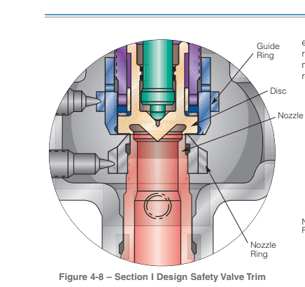
Modern relief valves are wonderfully modular.The internal parts for a relief valve (valve disc,disc holder, blowdown ringandspring) can be interchanged for ones with a different design to customize valve performance based on the application, fluid service, and set pressure.Valve disccan be metal-to-metal or soft seats. Soft seat designs use an elastomer to create a better seal between thevalvediscand thenozzle. Relief valves with elastomer seats have limitations and can only be used in certain applications.Disc holdersare generally designed to allow thevalve discto float which provides an angular movement that reduces seat leakage from minor misalignments (ensuring that thevalve dischas 360 degrees of contact with thenozzle). Thedisc holderoutside diameter, shape and thickness plays an important role in determining the valve performance by defining the shape of thehuddling chamber. Thehuddling chambercan also be defined by theblowdown ring(s). Thering(s)can also be swapped to different sized and shapedringsto adjust performance based on the expected relief fluid.Springsare selected to keep the valve closed and must fit inside thevalve bonnet. The force thespringexerts is an important design criteria for a relief device and varies depending on the relief fluid, valve size and set pressure.
Spring loaded relief valves are known as "pop action" relief valves as they typically pop open at their set pressure. Initially, the pressure differential across thevalve discthat creates the force to over come the spring force and open the valve.The pop action occurs because mosthuddling chambersare designed with an area that is approximately 10%-30% larger than thevalve seat(as thedisc holderis bigger than thevalve disc). Once the pressure under the seat is enough to lift thevalve discoff thenozzle, there is a step change in the upward forces on thespringand the valve "pops" open. The shape of thehuddling chamber(created by the shape and size of thedisc holder), the position and shape of theblowdown ring, and the characteristics of the fluid being relieved together determine the initial opening force and the initial lift of the valve.
Blowdown ringsare adjustable rings with a design shape that modifies the effluent flow path andhuddling chamberbased on the position. For process valves, a singleblowdown ringis typically threaded onto thenozzleand can be adjusted vertically up or down. Manufacturers will specify a recommended position relative to contact with thevalve disc. The position of theblowdown ringis fixed with a locking screw. The position of theblowdown ringchanges the blowdown (or reseat) pressure. For valves with a singleblowdown ring, the closer theblowdown ringis to thenozzle, the lower the pressure in the system will need to be for the valve to close (more blowdown). Other relief valves have multipleblowdown rings. Each manufacturer designs a uniqueblowdown ringto compliment other aspects of the relief valve design. Smith & Burgess" testing confirms that position and design ofblowdown ring(s)affects valve stability.
Relief Valve manufactures generally select aspringthat is designed for the set pressure of the valve. Thespringthat is selected will have a pressure range that thespringcan be applied. In many cases, there may be more than onespringthat can be used with each relief valve each having a different spring constant. The stifferspringmay have a range that is higher than the softerspringbut still meet the overall requirements for set pressure. The selection of thespringwill affect stability as the specific spring influences the natural frequency of the valve and can also affect the blowdown.
A fire-tube boiler can be fitted with one or more safety valves on the top of its shell, with each set to open when the boiler reaches its design pressure. Noisolation valvesor restrictions should be integrated between the safety valve(s) and boiler. If the valves are not installed directly onto the boiler shell, the pipework connecting the valves to the boiler must be kept clear of blockagesand water, and this must be confirmed by periodic testing.
Once a safety valve opens, steam is discharged via the exhaust pipe. Exhaust pipes must be designed to encounter as few bends as possible, be as short as possible, to have no reduction in pipe section (no internal pipe diameter reduction), and should lead to asafe point of discharge(typically outside the boiler house).
Water must be drained from the safety valve or exhaust pipework via a drainpipe. Drainpipes may be connected to holes drilled into the lowest section of the exhaust pipework, or, directly to drain holes in the safety valve body; these drains are not to be confused with the blowdown ring locking bolt, if one is fitted.
Where two safety valves are fitted, it is common that one is set just belowthe boiler’s design pressure. It is vital that each safety valve permits the full flow of steam produced when the boiler is operating at maximum capacity i.e. when the boiler is producing the maximum amount of steam it can possibly produce. If safety valves are sized correctly, a boiler can be firing at full capacity without the steam pressure exceeding design limits (because the safety valve(s) relieves pressure at a faster rate than it is accumulated).
There are various types of safety valve, including high lift and improved high lift valves, which use the force of escaping steam to open a winged valve plug to achieve greater steam flow rates. In addition to this, some valves integrate a pistonat the bottom of the spring chamber. The piston has a larger surface area than the valve plug, which leads to the valve opening with a definitive ‘pop’ sound.
Some boiler safety valves include a blowdown ring. The blowdown ring can raise or lower the valve seat ring and is used to control the amount of blowdown through the valve. This ring is locked by a bolt that protrudes through the valve and into the adjusting ring segments.
Boiler safety valves should be fitted with an easing gear (looks like a handle), used, when necessary, to rapidly release boiler pressure. Easing gears can also be used for testing a safety valve, ensuring the spindle has freedom of movement and that the valve operating mechanism functions as intended. Easing gear testing is often not conducted due to operators having difficulty with the valves resealing, but this is generally only the case with valves that are not tested often enough. Actuating the easing gear several times is often all it takes to dislodge debris from the sealing area and allow the valve to seal again. For safe operation, the easing gear handle is usually connected via steel cables to an area neighbouring the boiler.
Like pressure gauges, all safety valves should be stripped, inspected, and calibrated, at least once a year; maintenance usually occurs during statutory inspections. Calibration of each valve should be conducted by a competent person, and any valve adjustment (including the blowdown ring) should be approved and sealed by the authorised inspector. After testing and calibration, all valves should be correctly marked, suitable certificates issued, and accurate records maintained.
An accumulation test can be conducted to ensure a safety valve can relieve over-pressure steam when the boiler burner is operating at maximum capacity. Accumulation testing of safety valves must be repeated after any alterations are made to the boiler e.g. replacement of a safety valve, fuel change, or changes to the control system. If, during an accumulation test, boiler pressure rises by more than 10% of its design pressure, the test must be aborted. Before the boiler is re-tested, amendments must be made to either the safety valve relieving capacity, thesafety valve exhaust pipework, or the boiler’s steaming capacity, to ensure the 10% limit is never exceeded.
Reliefand safetyvalves prevent equipment damage by relieving over-pressurisation of fluid systems. The main difference between a relief valve and a safety valve is the extent of opening at the set-point pressure.
A relief valve gradually opens as the inlet pressure increases above the set-point. A relief valve opens only as necessary to relieve the over-pressure condition. Relief valves are typically used for liquid systems.
A safety valve rapidly‘pops’ fully openas soon as the pressure setting is reached and will stay fully open until the pressure drops below the reset pressure. The reset pressure is lower than the actuating set-point pressure. The difference between the actuating pressure set-point, and the pressure at which the safety valve resets, is called blowdown. Safety valves are typically used for gas or vapour systems.
A safety relief valve may open fully, or proportionally, once the pressure setting is reached. SRVs may be used for any fluid system (gas, liquid, or vapour).


 8613371530291