
boiler safety valve discharge piping free sample

Discharge pipe shall discharge independently by gravity through an air gap into the drainage system or outside of the building with the end of the pipe not exceeding 2 feet (610 mm) and not less than 6 inches (152 mm) above the ground and pointing downwards.
farishta - Based on your profile info, you"re located in The Netherlands so I assume this is for a European facility. If so, you need to get a copy of the ISO standard that applies to this type of steam boiler. I don"t work with steam boiler very often so I don"t remember the specific differences between the requirements in that ISO standard and ASME Sec I. I recall that they are similar, but there are some differences.
If this boiler was in an ASME jurisdiction, then you wouldn"t be allowed to install a muffler (ref: ASME Sec I, PG-71.4). Be aware that the rules for steam boilers are different from those for pressure vessels - that"s true in EU countries and in ASME jurisdictions. For example, the pressure drop rules don"t apply to steam boiler applications. Instead, the ASME Sec I rules prescriptively state that there must be as little as possible piping on the inlet and outlet side. ASME Sec I allows a muffler on boilers that operate at low T & P, but not for "high-temperature water boilers" which operate at a pressure greater than 160 psi or a temperature over 250F.
Boilers in EU countries and those in ASME jurisdictions must be inspected and approved by an independent boiler inspector. Even without the muffler, I don"t think any boiler inspector would approve a line pocket like the one shown in this installation. That pocket creates the dangerous possibility of the line being plugged in the wintertime due to ice, and/or the possibility of a "steam explosion" caused by high temperature steam mixing with water trapped in the pocket.
Boiler explosions have been responsible for widespread damage to companies throughout the years, and that’s why today’s boilers are equipped with safety valves and/or relief valves. Boiler safety valves are designed to prevent excess pressure, which is usually responsible for those devastating explosions. That said, to ensure that boiler safety valves are working properly and providing adequate protection, they must meet regulatory specifications and require ongoing maintenance and periodic testing. Without these precautions, malfunctioning safety valves may fail, resulting in potentially disastrous consequences.
Boiler safety valves are activated by upstream pressure. If the pressure exceeds a defined threshold, the valve activates and automatically releases pressure. Typically used for gas or vapor service, boiler safety valves pop fully open once a pressure threshold is reached and remain open until the boiler pressure reaches a pre-defined, safe lower pressure.
Boiler relief valves serve the same purpose – automatically lowering boiler pressure – but they function a bit differently than safety valves. A relief valve doesn’t open fully when pressure exceeds a defined threshold; instead, it opens gradually when the pressure threshold is exceeded and closes gradually until the lower, safe threshold is reached. Boiler relief valves are typically used for liquid service.
There are also devices known as “safety relief valves” which have the characteristics of both types discussed above. Safety relief valves can be used for either liquid or gas or vapor service.
Nameplates must be fastened securely and permanently to the safety valve and remain readable throughout the lifespan of the valve, so durability is key.
The National Board of Boiler and Pressure Vessel Inspectors offers guidance and recommendations on boiler and pressure vessel safety rules and regulations. However, most individual states set forth their own rules and regulations, and while they may be similar across states, it’s important to ensure that your boiler safety valves meet all state and local regulatory requirements.
The National Board published NB-131, Recommended Boiler and Pressure Vessel Safety Legislation, and NB-132, Recommended Administrative Boiler and Pressure Vessel Safety Rules and Regulationsin order to provide guidance and encourage the development of crucial safety laws in jurisdictions that currently have no laws in place for the “proper construction, installation, inspection, operation, maintenance, alterations, and repairs” necessary to protect workers and the public from dangerous boiler and pressure vessel explosions that may occur without these safeguards in place.
The American Society of Mechanical Engineers (ASME) governs the code that establishes guidelines and requirements for safety valves. Note that it’s up to plant personnel to familiarize themselves with the requirements and understand which parts of the code apply to specific parts of the plant’s steam systems.
High steam capacity requirements, physical or economic constraints may make the use of a single safety valve impossible. In these cases, using multiple safety valves on the same system is considered an acceptable practice, provided that proper sizing and installation requirements are met – including an appropriately sized vent pipe that accounts for the total steam venting capacity of all valves when open at the same time.
The lowest rating (MAWP or maximum allowable working pressure) should always be used among all safety devices within a system, including boilers, pressure vessels, and equipment piping systems, to determine the safety valve set pressure.
Avoid isolating safety valves from the system, such as by installing intervening shut-off valves located between the steam component or system and the inlet.
Contact the valve supplier immediately for any safety valve with a broken wire seal, as this indicates that the valve is unsafe for use. Safety valves are sealed and certified in order to prevent tampering that can prevent proper function.
Avoid attaching vent discharge piping directly to a safety valve, which may place unnecessary weight and additional stress on the valve, altering the set pressure.
A series of anomalies occurred in the boiler room that evening. The steel compression tank for the hydronic loop flooded, leaving no room for expansion. Water will expand at 3% of its volume when heated from room temperature to 180° F. When the burner fired, the expansion of the water increased the system pressure within the boiler. The malfunctioning operating control did not shut off the burner at the set point which caused the relief valve to open.
The brass relief valve discharge was installed with copper tubing piped solid to a 90° ell on the floor and the tubing further extended to the floor drain. The combination of hot water and steam from the boiler caused the discharge copper tubing to expand, using the relief valve as a fulcrum. The expansion of the copper discharge tubing pressing against the floor was enough to crack the brass relief valve, flooding the boiler room. The damage was not discovered until the next morning, several hours after the leak occurred. Thousands of dollars in damage was sustained and luckily no one was injured.
Each boiler requires some sort of pressure relieving device. They are referred to as either a safety, relief or safety relief valve. While these names are often thought of as interchangeable, there are subtle differences between them. According to the National Board of Boiler and Pressure Vessel Inspectors, the following are the definitions of each:
• Safety valve— This device is typically used for steam or vapor service. It operates automatically with a full-opening pop action and recloses when the pressure drops to a value consistent with the blowdown requirements prescribed by the applicable governing code or standard.
• Relief valve— This device is used for liquid service. It operates automatically by opening farther as the pressure increases beyond the initial opening pressure and recloses when the pressure drops below the opening pressure.
• Safety relief valve— This device includes the operating characteristics of both a safety valve and a relief valve and may be used in either application.
• Temperature and pressure safety relief valve— This device is typically used on potable water heaters. In addition to its pressure-relief function, it also includes a temperature-sensing element which causes the device to open at a predetermined temperature regardless of pressure. The set temperature on these devices is usually 210°.
• Relief valve piping— The boiler contractor installed a bushing on the outlet of the safety relief valve. Instead of 1 1/2-in. pipe, the installer used 3/4-in. pipe. When asked about it, he answered that he did not have any 1 1/2-in. pipe but had plenty of 3/4-in. pipe. I explained and then had to show the disbelieving contractor the code that states that the relief valve discharge piping has to be the same diameter as the relief valve outlet (see 2012 International Mechanical Code, 1006.6). By reducing the discharge pipe size, the relieving capacity of the safety valve may not be adequate to properly relieve the pressure inside the boiler, causing a dangerous situation.
The code also states that the discharge material shall be of rigid pipe that is approved for the temperature of the system. The inlet pipe size shall be full diameter of the pipe inlet for the relief valve. Some manufacturers suggest using black iron pipe rather than copper tubing. If using copper, it should have an air space that allows expansion should the relief valve open to avoid the accident that I referenced above. The discharge piping has to be supported and the weight of the piping should not be on the safety relief valve. Valves are not permitted in the inlet piping to or discharge piping from the relief valve. If you are using copper tubing on discharge piping, verify that there is room for expansion.
• Installation— Read the manufacturer’s installation manual as each may have different requirements. For instance, Conbraco requires that the discharge piping must terminate with a plain end and use a material that can handle temperatures of 375° or greater. This will preclude PVC or CPVC pipe for the discharge piping. The instruction manual for its model 12-14 steam relief valve stipulates that you cannot use a pipe wrench to install it. That would be good to know.
I once visited Boiler Utopia as the floor was clean and waxed. All the pipes were covered and exposed pipes were painted. There were large stickers detailing what was inside each pipe as well as directional arrows. Nothing was stacked next to the boilers. Yellow caution lines were painted on the floor around each boiler. I was in heaven. As I walked around the rear of the boiler, something clicked and triggered a warning bell. The discharge of the relief valve piping was about 6 in. from the floor but instead of a plain or angled cut end, the pipe had a threaded pipe cap on the termination. I asked the maintenance person about it and he said that the valve was leaking all over his newly waxed floor and this was the only way he could stop it. When I said that the discharge pipe should not have been threaded, he explained that it was not threaded and he had to take it to the local hardware store to thread it. I informed him that the cap had to be removed. We cut the pipe on an angle to prevent this.
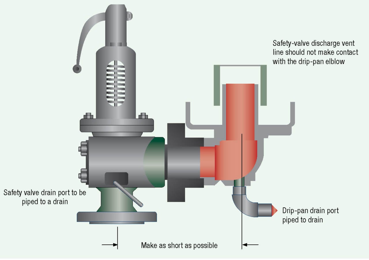
• Steam boiler— Most manufacturers recommend a drip pan ell on the discharge of the steam boiler relief valve to eliminate the weight of the discharge piping on the relief valve. Some codes require the discharge to be vented outdoors.
• Testing— I will ask the attendees in my classes, “How often do you test the relief valves?” Most do not make eye contact and when I follow up with, “Why are they not tested?” I often hear that opening the relief valve will cause it to leak. I suggest that you refer to each manufacturer’s directions for testing. For instance, one will recommend once a year while another recommends twice a year. One manufacturer says, “Safety/relief valves should be operated only often enough to assure they are in good working order.” I am not sure what that even means. You want to also verify the proper test procedure as some will only want the relief valve tested when the boiler is at 75% of the rated pressure or higher of the relief valve.

My name is Kelly Paffel, Technical Manager for Inveno Engineering, LLC, located in Tampa, Florida. We are an engineering firm focused on steam and condensate systems. Today I want to talk about steam safety valves: sizing, selection, installation, best practices. Steam safety valves installed wherever the maximum allowable working steam pressure of a system or over pressurizing a containing vessel is likely to be exceeded. In particular under fault conditions due to a failure of another piece of equipment in the system.
The typical system we have a pressure inducing valve here. We have a pressure 200 PSI here. And our equipment down here is only rated for 150 PSI, then we need to protect it with a safety relief valve. And typically, that safety relief valve will be set for the lowest rated equipment or component in the system; pressure and temperature rating.
The codes for this steam safety valve is governed by the American Society of Mechanical Engineers (ASME). ASME, through its committees, has established Boiler and Pressure Vessel Codes for safety though rules and formulas indicating a good practice. The National Board of Boiler and Pressure Vessel Inspectors has the authority to verify, administer and enforce this ASME code wherever it has been adopted. Therefore any safety valve that we must follow the code set out by ASME and under the jurisdiction of the national report.
Steam safety valve codes. In the steam system, we look at section one which is for the boilers or power boilers. Section 4 is for heating boilers and section 8 is for pressure vessels out there away from the boiler in the steam system. So, anything away from the boiler, we’re typically looking at section 8, safety valves. The example shows right here, this picture here shows the safety valve located on the boiler, which is going to be section 1.
The code stamps and it’s meaning, we have A, M, N, PP, S, U, U2, UV, and V. So these are the codes and these are the meanings of the code. For example, PP is pressure piping, S is for power boilers, U is for pressure vessels, and V is for boiler safety valves.
We’re going to discuss sizing and selection of a safety valve. We’re looking at the design type. The design type can be the standard safety valve, which is shown here, or we can use pilot operated. Then we have body drains, a lifting device here. Some people prefer to have a lifting device, some people do not prefer. Of course the materials here have to be rated for the max pressure and temperature of the system. So that depends on the material, so if we get in to the higher pressures, when we’re dealing with super heat, then materials have to be selected for that super heat pressure and temperature.
The sealing adjustments typically is adjustments here for the over pressurization in blow down, and the set point tolerance has got to be come up with on safety valves. Now, we’re now getting into the details on the internals of the safety valve and we’re going to talk about the selection process.
So here’s a typical application, we’re going to do this for pressure reduction. So we’re reducing steam pressure here, downstream here. Our equipment downstream, we have a device that only rated for 100PSI, 338 degrees. So we’re going to have to put in a safety valve here. So we’re reducing the pressure here to 50PSI for our operation, but we have to protect the system which is going to be 100PSI chain.
Now, the thing is that we typically have a 10 percent differential between the operating set pressures recommended, and the thing is that this pressure differential would be, if we’re operating at 100PSI, or our safety valve is set for 100PSI and we want to operate at 90PSI or lower. That’s due to, the safety valve can go into, what we call simmer[inaudible 00:05:27] so we want to be at least 10 percent away from our set pressure of our safety valve for the operating pressure of the system. Now, some people recommend 20 percent, and that gets into the lower pressure operation where we’re reducing pressures down to 10 or 12 PSI and we have our safety valve set there for 5PSI. So if my system safety valve is set for 15PSI, it would operate the system at 10PSI to stay away from that simmer effect of the safety valve and that’s per code that the safety valve can go into simmer.
The total capacity of a safety valve at set pressure must exceed the control valve or pressure-reducing valve’s maximum capacity, if the valve were to fail in a fully open position. So if this valve were to fail in the fully open position, this safety valve has to be able to discharge the total capacity. Now, total capacity of the boilers, is the maximum BTU fuel input on the boiler. So the safety valve must be able to relieve the maximum steam output with the maximum BTU input to that boiler, depending on the type of fuel that you’re using for that boiler. Multiple safety valve installation is possible if the capacity can not be reached with one safety valve. It’s common to find that with boilers that we have two or three safety valves to get to the capacity that’s required for that operation.
The steam safety valves sizing designation is designated by numbers. Excuse me. Letters. So up here you’ll see the letters, here. K, L, M, N, P. That gives us the effective orifice area. So if I have a set pressure here 100 PSI, and a P orifice, we have this capacity here, which is around 37012 pounds per hour. So we look up the safety valve and see 4 by 6 P. P means the orifice inside the safety valve.
Now, a safety relief valve must be mounted in the vertical position. The reason mounted in the vertical position is a safety valve is set up as assembled or manufactured in the vertical position, so you must duplicate how the position is of the safety valve. The system must be free of dirt of course. Upstream piping connection must be at least equal to the valve, so if the end of the valve is 6 inches, then this connection valve here needs to be 6 inches.
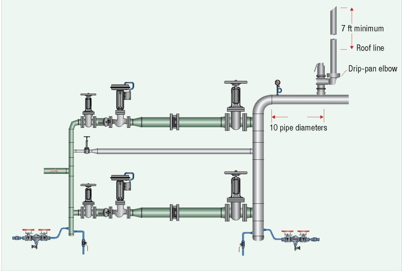
With the steam safety valve no shutoff valve can be installed down here, and do not plug the drain valves, and the discharge lines should be no less than the full area of the valve. In the [inaudible 00:08:38] that make sure we have a drip pan elbow put onto the valve, and this just changes direction from horizontal to vertical, and increases the pipe on pipe diameter, and then the vent pipe can come down but does not make contact with the drip pan elbow. The outlet always must discharge where no one can be at harm’s way, typically to the top of the building or the unit, and cut it at a 45 degree angle to signify it’s a steam safety valve. So you cut it at a 45 degree angle, it used to be 7 feet, and this has recently changed, it’s now 10 feet above. That’s a typical installation of a safety valve.
We also have best practices up on the website, to go into more detail on safety valves, but this is just a short version to give you some idea. So if we can be of service, here is out contact information, and have a great day.

The safety valve is widely used in a steam boiler, LPG tanker, oil well, high-pressure bypass, pressure pipeline, pressure vessel of steam power generation equipment, and etc. The safety valve is closed under the action of external force on the opening& closure parts and when the pressure of the medium in the equipment or pipeline exceeds the specified value, it opens and drains the medium out of the system to protect the safety of the pipeline or equipment.
The safety valve shall be installed upright and as close as possible to the protected equipment or piping. If not installed nearby, the total pressure drop between the pipe and the safety valve inlet should not exceed 3% of the valve’s constant pressure value or 1/3 of the maximum allowable open/closed pressure difference (whichever is the lesser). In engineering practice, the total pressure drop of the pipeline can be reduced by expanding the inlet diameter of the safety valve appropriately, adopting a long radius elbow and reducing the number of the elbow. Besides, what else should be considered?
The safety valve shall be installed in a place convenient for maintenance and a platform shall be set up for maintenance. The large diameter safety valve should consider the possibility of lifting after the safety valve is disassembled. In engineering practice, the safety valve is often mounted on top of the piping system.
The safety valve for a liquid pipeline, heat exchanger or pressure vessel, which can be installed horizontally when the pressure increases due to thermal expansion after the valve is closed; The outlet of the safety relief valve shall be free of resistance to avoid backpressure and to prevent the accumulation of solid or liquid materials.
The inlet pipe of the safety valve shall have a long radius elbow with at least 5% bend. The inlet pipe should avoid u-bend as far as possible, otherwise, the condensable material at the lowest point is connected with the continuous flow drain pipe to the same pressure system, the viscous or solid condensate needs the heat tracing system. In addition, the backpressure of the outlet line shall not exceed the specified value of the relief valve. For example, the backpressure of the ordinary spring safety valve does not exceed 10% of its fixed value.
The sectional area of the connecting pipe between the safety valve and the boiler pressure vessel shall not be less than that of the safety valve. The whole safety valve is installed on a joint at the same time, the cross-section area of the joint shall not be less than 1.25 times of the safety valve.
The outlet pipeline of the relief valve discharged into the closed system shall be connected to the top of the relief main pipe according to the medium flow direction of 45°, so as to avoid the condensate in the main pipe flowing into the branch pipe and reduce the backpressure of the relief valve.
If the outlet of the safety valve is lower than the relief pipe or the discharge pipe, it is necessary to raise the access pipe. In steam service, the safety valve shall be installed so that the condensate does not converge upstream of the disc.
If a discharge line is to be installed, the inside diameter shall be greater than the outlet diameter of the relief valve. For containers of inflammable or toxic or highly toxic media, the discharge line shall be directly connected to an outdoor or safe place with treatment facilities. No valves shall be installed on the discharge line. In addition, flammable, explosive or toxic media pressure vessels must have safety devices and recovery systems. The outlet of the discharge line shall not be directed towards equipment, platforms, ladders, cables, etc.
When the safety valve cannot be mounted on the container body due to special reasons, it can be considered to be mounted on the outlet pipeline. However, the pipeline between them should avoid sudden bending and the outer diameter should be reduced, so as to avoid increasing the pipeline resistance and causing dirt accumulation and blockage. In addition, a power assist device (actuator) is used to open the safety valve when the pressure is lower than the normal set pressure. As a kind of special equipment, when selecting the safety valve, it is necessary to consider the nature of the medium, the actual working condition, the valve material and connection mode and related parameters.

Safety valves are precision items of safety equipment; they are set to close tolerances and have accurately machined internal parts. They are susceptible to misalignment and damage if mishandled or incorrectly installed.
Valves should be transported upright if possible and they should never be carried or lifted by the easing lever. In addition, the protective plugs and flange protectors should not be removed until actual installation. Care should also be taken during movement of the valve to avoid subjecting it to excessive shock as this can result in considerable internal damage or misalignment.
When designing the inlet pipework, one of the main considerations is to ensure that the pressure drop in this pipework is minimised. EN ISO 4126 recommends that the pressure drop be kept below 3% of the set pressure when discharging. Where safety valves are connected using short ‘stub’ connections, inlet pipework must be at least the same size as the safety valve inlet connection. For larger lines or any line incorporating bends or elbows, the branch connection should be at least two pipe sizes larger than the safety valve inlet connection, at which point it is reduced in size to the safety valve inlet size (see Figure 9.5.5a). Excessive pressure loss can lead to ‘chatter’, which may result in reduced capacity and damage to the seating faces and other parts of the valve. In order to reduce the pressure loss in the inlet, the following methods can be adopted:
Safety valves should always be installed with the bonnet vertically upwards. Installing the valve in any other orientation can affect the performance characteristics.
The API Recommended Practice 520 guidelines also state that the safety valve should not be installed at the end of a long horizontal pipe that does not normally have flow through it. This can lead to the accumulation of foreign material or condensate in the pipe, which may cause unnecessary damage to the valve, or interfere with its operation.
There are two possible types of discharge system – open and closed. An open system discharges directly into the atmosphere whereas a closed system discharges into a manifold along with other safety valves.
It is recommended that discharge pipework should rise for steam and gas systems, whereas for liquids, it should fall. Horizontal pipework should have a downward gradient of at least 1 in 100 away from the valve ensuring that any discharge will be self-draining. It is important to drain any rising discharge pipework. Vertical rises will require separate drainage. Note: all points of system drainage are subject to the same precautions, notably that valve performance must not be affected, and any fluid must be discharged to a safe location.
It is essential to ensure that fluid cannot collect on the downstream side of a safety valve, as this will impair its performance and cause corrosion of the spring and internal parts. Many safety valves are provided with a body drain connection, if this is not used or not provided, then a small bore drain should be fitted in close proximity to the valve outlet (see Figure 9.5.3).
One of the main concerns in closed systems is the pressure drop or built-up backpressure in the discharge system. As mentioned in Module 9.2, this can drastically affect the performance of a safety valve. The EN ISO 4126: Part 1 standard states that the pressure drop should be maintained below 10% of the set pressure. In order to achieve this, the discharge pipe can be sized using Equation 9.5.1.
Calculate the nominal diameter of the discharge pipework for a safety valve required to discharge 1 000 kg/h of saturated steam; given that the steam is to be discharged into a vented tank via the pipework, which has an equivalent length of 25 m. The set pressure of the safety valve is 10 bar g and the acceptable backpressure is 10% of the set pressure. (Assume zero pressure drop along the tank vent).
Therefore, the pipework connected to the outlet of the safety valve should have an internal diameter of at least 54 mm. With schedule 40 pipe, this would require a DN65 pipe.
Balanced safety valves require that their bonnets be vented to atmosphere. In the case of the balanced bellows type, there will be no discharge of the process fluid, so they can be vented directly to the atmosphere. The main design consideration is to ensure that this vent will not become blocked, for example, by foreign material or ice. With the balanced piston type, consideration must be given to the fact that process fluid may be discharged through the bonnet vent. If discharging to a pressurised system, the vent has to be suitably sized, so that no backpressure exists above the piston.
Safety valves that are installed outside of a building for discharge directly into the atmosphere should be covered using a hood. The hood allows the discharge of the fluid, but prevents the build up of dirt and other debris in the discharge pipework, which could affect the backpressure. The hood should also be designed so that it too does not affect the backpressure.
Manifolds must be sized so that in the worst case (i.e. when all the manifold valves are discharging), the pipework is large enough to cope without generating unacceptable levels of backpressure. The volume of the manifold should ideally be increased as each valve outlet enters it, and these connections should enter the manifold at an angle of no greater than 45° to the direction of flow (see Figure 9.5.6). The manifold must also be properly secured and drained where necessary.
In open systems, careful consideration must be given to the effects of the reaction forces generated in the discharge system when the valve lifts. In these systems, there will be significant resultant force acting in the opposite direction to that of discharge. It is important to prevent excessive loads being imposed on the valve or the inlet connection by these reaction forces, as they can cause damage to the inlet pipework. The magnitude of the reaction forces can be calculated using the formula in Equation 9.5.2:
The reaction forces are typically small for safety valves with a nominal diameter of less than 75 mm, but safety valves larger than this usually have mounting flanges for a reaction bar on the body to allow the valve to be secured.
Regardless of the magnitude of the reaction forces, the safety valve itself should never be relied upon to support the discharge pipework itself and a support should be provided to resist the weight of the discharge pipework. This support should be located as close as possible to the centreline of the vent pipe (see Figure 9.5.7).
Changeover valves (see Figure 9.5.10) permit two valves to be mounted side by side, with one in service and one isolated. This means regular maintenance can be carried out without interruption of service or the vessel being protected. Changeover valves are designed in such a way that when they are operated, the pass area is never restricted.
Changeover valves can also be used to connect safety valve outlets so that the discharge pipework does not have to be duplicated. The action of both inlet and outlet changeover valves has to be limited and synchronised for safety reasons. This is usually by means of a chain drive system linking both handwheels.
Consideration must be made to pressure loss caused by the changeover valve when establishing the safety valve inlet pressure drop, which should be limited to 3% of the set pressure.

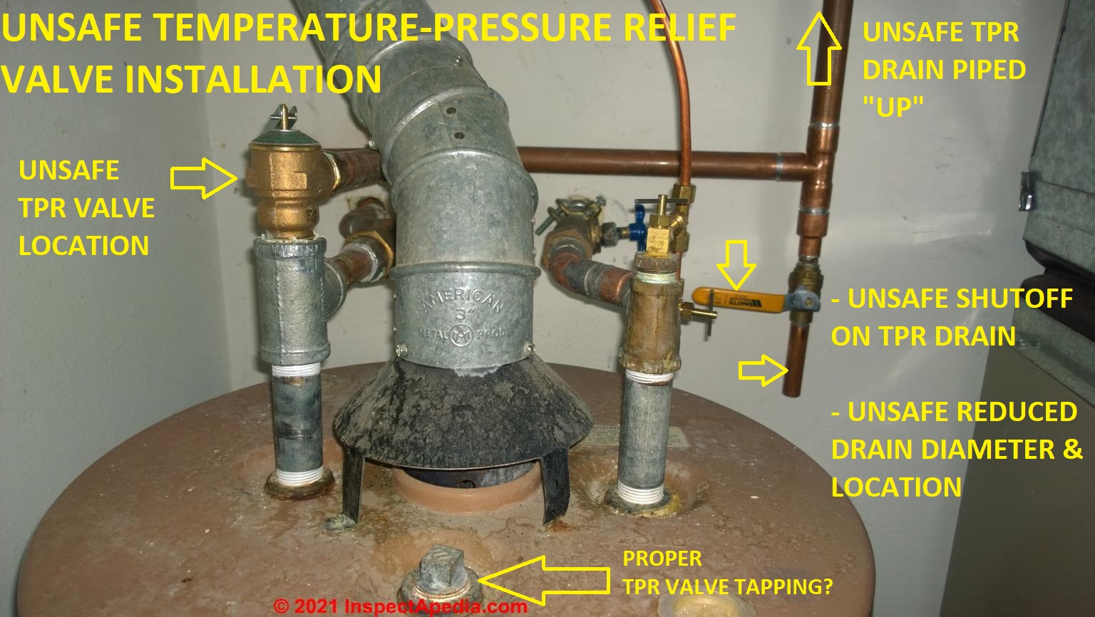
Temperature/pressure-relief or TPR valves are safety devices installed on water heating appliances, such as boilers and domestic water supply heaters. TPRs are designed to automatically release water in the event that pressure or temperature in the water tank exceeds safe levels.
If temperature sensors and safety devices such as TPRs malfunction, water in the system may become superheated (exceed the boiling point). Once the tank ruptures and water is exposed to the atmosphere, it will expand into steam almost instantly and occupy approximately 1,600 times its original volume. This process can propel a heating tank like a rocket through multiple floors, causing personal injury and extensive property damage.
Water-heating appliance explosions are rare due to the fact that they require a simultaneous combination of unusual conditions and failure of redundant safety components. These conditions only result from extreme negligence and the use of outdated or malfunctioning equipment.
The TPR valve will activate if either water temperature (measured in degrees Fahrenheit) or pressure (measured in pounds per square inch [PSI]) exceed safe levels. The valve should be connected to a discharge pipe (also called a drain line) that runs down the length of the water heater tank. This pipe is responsible for routing hot water released from the TPR to a proper discharge location.
It is critical that discharge pipes meet the following requirements, which can be found in InterNACHI’s Water Heater Discharge Piping mini-course, at www.nachi.org/education. A discharge pipe should:
discharge to a termination point that is readily observable by occupants, because discharge indicates that something is wrong, and to prevent unobserved termination capping.
A properly functioning TPR valve will eject a powerful jet of hot water from the discharge pipe when fully activated, not a gentle leak. A leaky TPR valve is an indication that it needs to be replaced. In the rare case that the TPR valve does activate, the homeowner should immediately shut off the water and contact a qualified plumber for assistance and repair.
Inspectors should recommend that homeowners test TPR valves monthly, although inspectors should never do this themselves. The inspector should demonstrate to the homeowner how the main water supply can be shut off, and explain that it can be located at the home"s main water supply valve, or at the water supply shut-off for the appliance on which the TPR is mounted.
The pressure at which a TPR valve will activate is printed on a data plate located beneath the test lever. This amount should not exceed the working pressure limit marked on the data plate of the water-heating appliance it serves.
TPR valves with missing data plates should be replaced.Although a TPR valve might never become activated, it is an essential safety component on boilers and domestic water heaters. Guidelines concerning these valves and their discharge pipes reflect real hazards that every homeowner and home inspector should take seriously. More information about this subject can be found in InterNACHI"s Water Heater Discharge Piping mini-course, InterNACHI"s Plumbing Inspection course or by contacting a qualified plumber.


 8613371530291