
boiler safety valve discharge piping pricelist

Boiler contractors see these valves all the time when working on equipment. Generally the steam relief valve is often little understood, often incorrectly installed, and usually neglected. A little refresher on these valves might be in order.
As the pressure of the steam within a boiler approaches the set pressure of the valve, the steam pressure on the underside of the actuating disc approaches the pressure of a spring applied to the outer side of the disc. When equilibrium is passed, the disc starts to lift off its seat. The moment this happens, steam is suddenly released all around the disc to what is called the “huddling chamber.” This chamber increases the area of the disc that sees steam pressure, thus increasing force. This increased area under steam pressure makes the pressure much more unbalanced in the direction of the valve discharge opening and therefore pops the valve into a wide open position. When the valve opens with a “pop” the valve seat is preserved from wiredraw caused by slow opening.
Closure of the valve occurs only after the boiler pressure is dropped several pounds below the set point. The reduction of the area of the disc seeing steam causes the disc to firmly close against the valve seat.
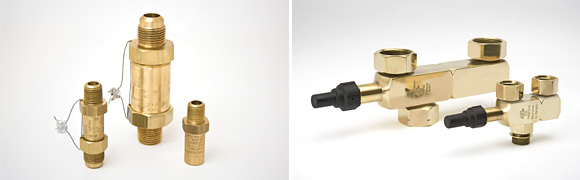
The first area of concern is valve distortion. Valve distortion occurs when the valve is improperly wrenched in, using the valve body instead of supplied wrench flats. Distortion also occurs when the discharge side of the safety relief valve is made to bear the weight of the discharge piping. To prevent this distortion use a short nipple from the valve to an independently supported bell reducer or drip pan elbow. These valves are precision devices and any distortion will affect accuracy and calibration.
The second area of concern is discharge piping. For a safety valve to do its job it must be sized properly to adequately relieve all the steam the boiler is capable of producing while operating at its maximum. All piping to or from a safety relief valve must be at least as large as the valve’s connections. Also, the restrictive effect of elbows and the friction losses in pipe must be taken into account. For this reason, piping runs should be as short as possible and pipe sizes should be generous.
If you need help in replacing or sizing a steam relief valve please contact Stromquist and Company at 1-800-241-9471. All others can order this product from one of our affiliates at CGNA.

Stainless Steel Safety Relief Valve is a safety mechanism deployed in applications to prevent them from bursting under pressure. Suraj Metal Corporationis a leading manufacturer and supplier of the different types such as the Brass Safety Valveand others in various sizes and dimensions. The valves are fitted with the pipelines in a way that when the pressure goes above the threshold level, the Stainless Steel Air Safety Valveopens up and relieves the system of pressure.
This is important to prevent the pipes from being damaged or bursting under high pressure. The Stainless Steel Safety Exhaust Ball Valveis used in the exhaust systems where the temperature plays major role. When the temperature exceeds certain point, it increases pressure and the safety valve opens and balances the pressure in the system. The spring loaded boiler safety valveis used in boilers and heat exchanger systems where steam and hot water are circulated through pipes. There are different gas safety valvetypes and each of these differ in their purpose and functions. Please feel free to contact us for more information on the different types of air compressor pressure relief valveand others with pricing.
We Keep Bulk Stock of CF8 stainless steel Pressure Safety Valve at our stockyard, contact us for Free Sample & stock list, View Brass Safety Valve Dimension chart
find Stainless Steel Safety Exhaust Ball Valve Dimensions, price list, size chart here, Buy ASTM A351 CF8M 316 temperature safety valve at best price in India

Relief valves are designed to open at a preset pressure (or temperature) level and relieve the system when it has exceeded the desired level. The valve"s relief of elevated liquid, gas, or steam pressures prevents damage to the system. We offer a wide selection of relief valves for any application.

Pressure relief devices are used to provide a means of venting excess pressure which could rupture a boiler or pressure vessel. A pressure relief device is the last line of defense for safety. If all other safety devices or operating controls fail, the pressure relief device must be capable of venting excess pressure.
There are many types of pressure relief devices available for use in the boiler and pressure vessel industry. This inspector guide will address the most common devices found on boilers and pressure vessels. Virtually all jurisdictions require a pressure relief device to be manufactured and certified in accordance with the ASME BPV Code in addition to being capacity-certified by the National Board.
Safety Valve – This device is typically used for steam or vapor service. It operates automatically with a full-opening pop action and recloses when the pressure drops to a value consistent with the blowdown requirements prescribed by the applicable governing code or standard.
Relief Valve – This device is typically used for liquid service. It operates automatically by opening farther as the pressure increases beyond the initial opening pressure and recloses when the pressure drops below the opening pressure.
Safety Relief Valve – This device includes the operating characteristics of both a safety valve and a relief valve and may be used in either application.
Temperature and Pressure Safety Relief Valve – This device is typically used on potable water heaters. In addition to its pressure-relief function, it also includes a temperature-sensing element which causes the device to open at a predetermined temperature regardless of pressure. The set temperature on these devices is usually 210°F.
The inlet piping connected to the device must not be smaller in diameter than the inlet opening of the device. An inlet pipe that is smaller than the device inlet opening could alter the operating characteristics for which the device was designed.
The discharge piping connected to the device must be no smaller than the discharge opening of the device. A discharge pipe that is smaller than the device discharge opening could cause pressure to develop on the discharge side of the device while operating.
Multiple devices discharging into a discharge manifold or header is a common practice. The discharge manifold or header must be sized so the cross-sectional area is equal to or greater than the sum of the discharge cross-sectional areas of all the devices connected to the discharge manifold or header. Failing this requirement, the devices would be subjected to pressure on the discharge side of the device while operating. Even a small amount of pressure here could adversely affect the operation of the device.
Constant leakage of the device can cause a build-up of scale or other solids around the discharge opening. This build-up can prevent the device from operating as designed.
Discharge piping connected to the device must be supported so as not to impart any loadings on the body of the device. These loadings could affect or prevent the proper operation of the device including proper reclosure after operating.
Some devices, especially on larger boilers, may have a discharge pipe arrangement which incorporates provisions for expansion as the boiler heats up or cools down. These expansion provisions must allow the full range of movement required to prevent loads being applied to the device body.
Drain holes in the device body and discharge piping, when applicable, must be open to allow drainage of liquids from over the device disk on spring loaded valves. Any liquid allowed to remain on top of the device disk can adversely affect the operating characteristics of the device.
Most jurisdictional requirements state the device must be "piped to a point of safe discharge." This must be accomplished while keeping the run of discharge piping as short as possible. Most jurisdictions also limit the number of 90 degree elbows that may be installed in the discharge piping. Too long of a run and multiple elbows can adversely affect the operation of the device.
While inspecting a boiler or pressure vessel, the inspector will also be evaluating the pressure relief device(s) installed on, or associated with, the equipment. The inspector should:
Compare the device nameplate set pressure with the boiler or pressure vessel maximum allowable working pressure (MAWP) and ensure the device set pressure does not exceed the MAWP. A device with a set pressure less than MAWP is acceptable. If multiple devices are used, at least one must have a set pressure equal to or less than the MAWP. The ASME Code should be reviewed for other conditions relating to the use of multiple devices.
Instruct the owner or owner"s representative to lift the test lever, if so equipped, on spring-loaded devices. ASME BPV Code Section IV devices can have the test levers lifted without pressure in the boiler. All other devices must have at least 75% of the device set pressure under the device disk prior to lifting the test lever. If the device is found to be stuck in a closed position, the equipment should be immediately removed from service until such time the device can be replaced or repaired.
The small pressure relief devices found on many air compressor vessels have a ring inserted through a drilled hole on the end of the device stem. These are tested by pulling the stem straight out and then releasing. The discharge openings in this type of device are holes drilled around the periphery of the device. These holes often get filled with oily dust and grit which can cause eye damage when the device is tested. A rag, loosely wrapped around the device when testing, can help prevent personal injury from the dust and grit.

Safety valves or pressure relief valves are pressure regulating devices that are responsible for expelling excess pressure from the system when the maximum pressure levels for which they have been designed are exceeded, usually due to a
Safety valves perform their function when the pressure of the system where the fluid is contained, becomes higher than the maximum set pressure of the valve previously adjusted. When the system pressure is higher than the valve’s set
pressure, this opens, releasing the excess pressure to the atmosphere or to containment tanks, depending on the toxicity of the fluid. After releasing the excess, the valve closes again and the system pressure returns to normal.
To ensure total safety of personnel and installation, make sure that the valves have passed all safety tests and meet the requirements of the system where they are to be installed. All our valves are supplied with certificates of materials, cas-
What is the difference between the instantaneous full opening safety valve AIT (PSV) and the normal opening relief valve AN or progressive opening relief valve AP (PRV)?
The Pressure Safety Valve (PSV) opens instantaneously and fully upon reaching the set pressure for which it is designed, expelling the excess pressure from the system immediately. They are optimised for use with steam or gases.
In contrast, the normally or progressively opening Pressure Relief Valve (PRV) opens gradually as the system pressure rises above the set pressure of the valve above its setting. They are optimised to work with liquids.
At VYC Industrial we are specialists in the design and manufacture of all types of safety valves. We have a wide range of safety valves to cover all the needs of the sector.
The Mod. 496 EN safety valve works as an automatic pressure releasing regulator activated by the static pressure existing at the entrance to the valve and is characterized by its ability to open instantly and totally.
The Mod. 495 EN pressure relief valve works as an automatic pressure releasing regulator activated by the static pressure existing at the entrance to the valve and is characterized by its ability to open instantly and totally.
The relief valve works as an automatic pressure releasing regulator activated by the static pressure existing at the entrance to the valve and is characterized by its ability to open instantly and totally.
The valve works as an automatic pressure releasing regulator activated by the static pressure existing at the entrance to the valve and is characterized by its ability to open instantly and totally.
The valve works as an automatic pressure releasing regulator activated by the static pressure existing at the entrance to the valve and is characterized by its ability to open instantly and totally.
The valve works as an automatic pressure releasing regulator activated by the static pressure existing at the entrance to the valve and is characterized by its ability to open instantly and totally.
The valve works as an automatic pressure releasing regulator activated by the static pressure existing at the entrance to the valve and is characterized by its ability to open instantly and totally.
The valve works as an automatic pressure releasing regulator activated by the static pressure existing at the entrance to the valve and is characterized by its ability to open instantly and totally.
The valve works as an automatic pressure releasing regulator activated by the static pressure existing at the entrance to the valve and is characterized by its ability to open, at the fi rst proportional to the pressure increase, and after instantly and totally.
The valve works as an automatic pressure releasing regulator activated by the static pressure existing at the entrance to the valve and is characterized by its ability to open, at the fi rst proportional to the pressure increase, and after instantly and totally.
The valve works as an automatic pressure releasing regulator activated by the static pressure existing at the entrance to the valve and is characterized by its ability to open, at the fi rst proportional to the pressure increase, and after instantly and totally.
The valve works as an automatic pressure releasing regulator activated by the static pressure existing at the entrance to the valve and is characterized by its ability to open proportional to the pressure increase.
The valve works as an automatic pressure releasing regulator activated by the static pressure existing at the entrance to the valve and is characterized by its ability to open proportional to the pressure increase.
The valve works as an automatic pressure releasing regulator activated by the static pressure existing at the entrance to the valve and is characterized by its ability to open instantly and totally.
The valve works as an automatic pressure releasing regulator activated by the static pressure existing at the entrance to the valve and is characterized by its ability to open instantly and totally.
The valve works as an automatic pressure releasing regulator activated by the static pressure existing at the entrance to the valve and is characterized by its ability to open instantly and totally.
The valve works as an automatic pressure releasing regulator activated by the static pressure existing at the entrance to the valve and is characterized by its ability to open instantly and totally.
The valve works as an automatic pressure releasing regulator activated by the static pressure existing at the entrance to the valve and is characterized by its ability to open instantly and totally.
They are used in places such as power, chemical and petrochemical plants to discharge safety valves, control valves, etc. in pressure lines and equipment that convey compressible substances such as steam, air, carbon dioxide, helium, methane, nitrogen, oxygen and other gases.
Test bench for regular inspections and setting and resetting safety valves. Ideal for distributors, maintenance companies or with in-house maintenance. It allows safety valves to be adjusted, tested and/or checked to the test pressure (setting) Pe wile cold (simulating service conditions), matching the opening pressure Ps and the closing pressure Pc, in accordance with the standard regulations.
Controlled safety pressure relief system CSPRS valves are mainly used where conventional direct-loaded spring action valves cannot guarantee the opening and closing margins that certain specifi c conditions of service demand.
The objective is to help the closure by means of pressure so that the valve remains completely watertight until reaching the set pressure and/or to activate the opening with pressure.
Increase the operating pressure of the system up to 99.9% of the set pressure.The control safety pressure relief system CSPRS device can be used with any safety valve available in the market and in particular, with models VYC Mod. 485, 486, 494, 495 and 496.
(a) Each power boiler, nuclear boiler, and high temperature water boiler shall have safety valves or pressure relieving devices constructed, stamped and installed in accordance with the applicable section of the Code, except:
(2) Upon written request by the employer, the Division may permit three-way two-port valves to be installed under two safety valves, each with the required relieving capacity, provided they are so installed that both safety valves cannot be closed off from the boiler at the same time and provided the three-way valve will permit at least full flow to the safety valve in service at all time.
(b) The user shall maintain all pressure relieving devices in good operating condition. Where the valves cannot be tested in service, the user shall maintain and make available to the inspector records showing the test dates and set pressure for such valves.
(c) Pressure relieving devices with open discharge installations shall have piping and supports designed for pressure relief reaction forces in accordance with Appendix II of ANSI B 31.1.


 8613371530291