
boiler safety valve discharge piping quotation
Boiler explosions have been responsible for widespread damage to companies throughout the years, and that’s why today’s boilers are equipped with safety valves and/or relief valves. Boiler safety valves are designed to prevent excess pressure, which is usually responsible for those devastating explosions. That said, to ensure that boiler safety valves are working properly and providing adequate protection, they must meet regulatory specifications and require ongoing maintenance and periodic testing. Without these precautions, malfunctioning safety valves may fail, resulting in potentially disastrous consequences.
Boiler safety valves are activated by upstream pressure. If the pressure exceeds a defined threshold, the valve activates and automatically releases pressure. Typically used for gas or vapor service, boiler safety valves pop fully open once a pressure threshold is reached and remain open until the boiler pressure reaches a pre-defined, safe lower pressure.
Boiler relief valves serve the same purpose – automatically lowering boiler pressure – but they function a bit differently than safety valves. A relief valve doesn’t open fully when pressure exceeds a defined threshold; instead, it opens gradually when the pressure threshold is exceeded and closes gradually until the lower, safe threshold is reached. Boiler relief valves are typically used for liquid service.
There are also devices known as “safety relief valves” which have the characteristics of both types discussed above. Safety relief valves can be used for either liquid or gas or vapor service.
Nameplates must be fastened securely and permanently to the safety valve and remain readable throughout the lifespan of the valve, so durability is key.
The National Board of Boiler and Pressure Vessel Inspectors offers guidance and recommendations on boiler and pressure vessel safety rules and regulations. However, most individual states set forth their own rules and regulations, and while they may be similar across states, it’s important to ensure that your boiler safety valves meet all state and local regulatory requirements.
The National Board published NB-131, Recommended Boiler and Pressure Vessel Safety Legislation, and NB-132, Recommended Administrative Boiler and Pressure Vessel Safety Rules and Regulationsin order to provide guidance and encourage the development of crucial safety laws in jurisdictions that currently have no laws in place for the “proper construction, installation, inspection, operation, maintenance, alterations, and repairs” necessary to protect workers and the public from dangerous boiler and pressure vessel explosions that may occur without these safeguards in place.
The American Society of Mechanical Engineers (ASME) governs the code that establishes guidelines and requirements for safety valves. Note that it’s up to plant personnel to familiarize themselves with the requirements and understand which parts of the code apply to specific parts of the plant’s steam systems.
High steam capacity requirements, physical or economic constraints may make the use of a single safety valve impossible. In these cases, using multiple safety valves on the same system is considered an acceptable practice, provided that proper sizing and installation requirements are met – including an appropriately sized vent pipe that accounts for the total steam venting capacity of all valves when open at the same time.
The lowest rating (MAWP or maximum allowable working pressure) should always be used among all safety devices within a system, including boilers, pressure vessels, and equipment piping systems, to determine the safety valve set pressure.
Avoid isolating safety valves from the system, such as by installing intervening shut-off valves located between the steam component or system and the inlet.
Contact the valve supplier immediately for any safety valve with a broken wire seal, as this indicates that the valve is unsafe for use. Safety valves are sealed and certified in order to prevent tampering that can prevent proper function.
Avoid attaching vent discharge piping directly to a safety valve, which may place unnecessary weight and additional stress on the valve, altering the set pressure.
This article describes the requirements for a discharge tube or drain line on temperature & pressure relief valves used on any appliance that heats water. These include hydronic heating boilers (hot water boilers), steam boilers, and all types of water heaters, both those that use a water storage tank or cylinder and those that heat water on demand such as tankless water heaters.
Here we describe the installation specifications for TPR valve drain line piping and we include an extensive list of discharge tube installation or condition defects, most of which are unsafe. All of them are improper.
The Temperature & Pressure Relief Valve or TPR Valve on any heated appliance that contains water, such as a heating boiler, hot water tank, water heater, water cylinder, must have a drain line or discharge tube properly installed, routed, and made of proper materials. The purpose of this drain line is to discharge potentially hot scalding water to a safe location so that a bystander is not scalded.
At left we see a typical TPR valve installation (by the author) including the vertical 3/4" copper drain piping that will discharge any T&P valve spillage to the floor.
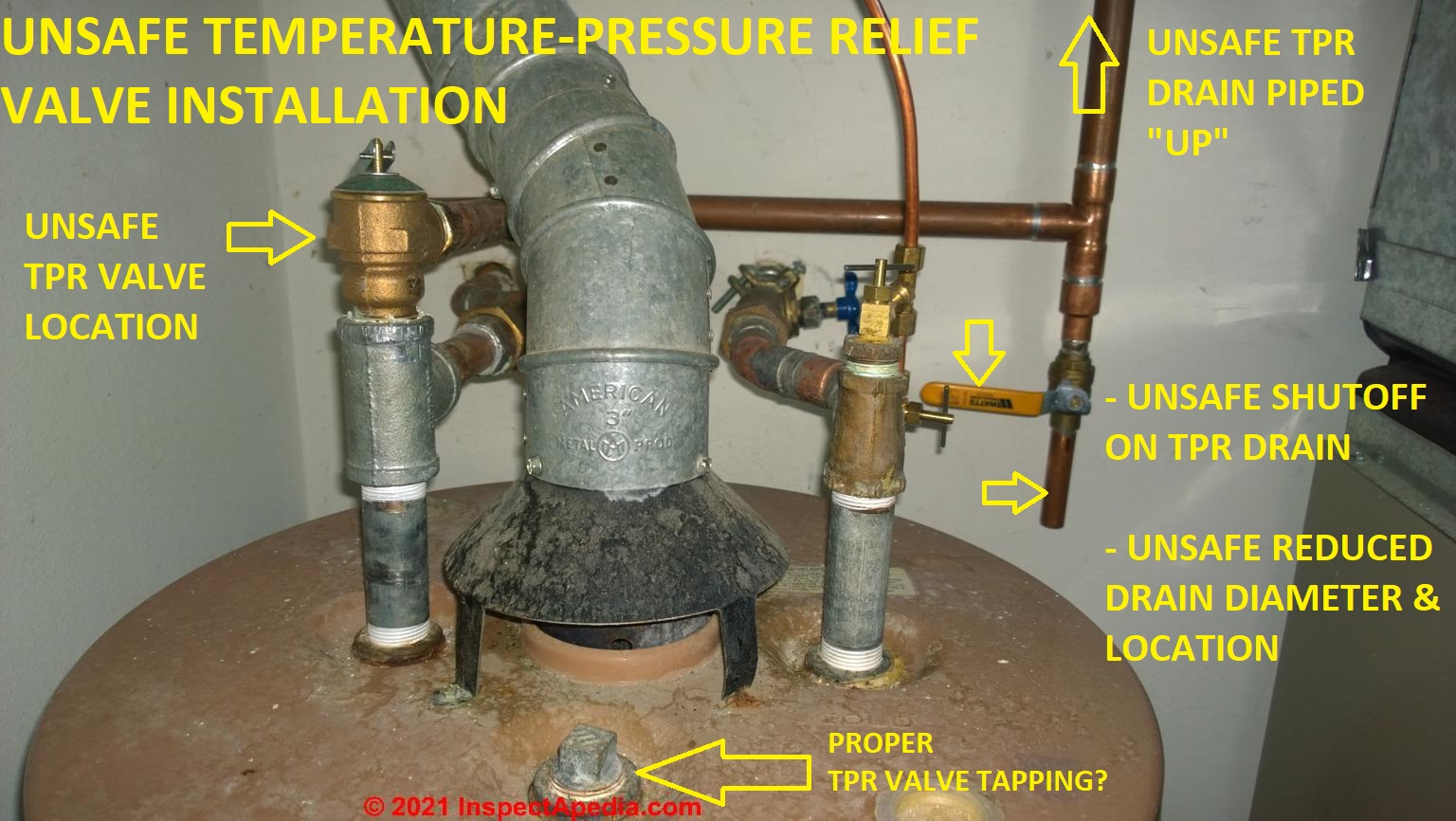
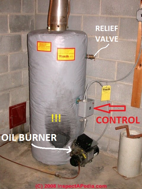
An unsafe TPR drain line installation is shown at the top of this page. Only a complete fool would do what we found on this boiler. To "stop" an annoying boiler drip at the pressure temperature relief valve, the mechanic installed a short length of pipe capped by a drain valve which he could simply shut. This might have been installed on a system for other reasons, such as connecting a hose to permit easy draining of pressure off of the boiler through the TP valve.
But it is in all events dangerous, illegal, and plain stupid to ever install a shutoff valve or any other sort of "cap" on a pressure/temperature relief valve.
But how dangerous is it to omit a discharge drain tube on a TPR valve? The possibility of a scalding burn is obvious but do these accidents actually happen?
Noticing that a TPR discharge tube was missing on a heating boiler during a home inspection I [DF] pointed out this safety hazard to my client while the real estate agent nearby frowned at my "old maid" trouble-making personality.
My client burst into tears. Sobbing she told me that she was grateful that inspectors would routinely point-out this hazard. Her son, playing with friends in the basement, lost an eye when he and a pal opened the discharge lever on a heating boiler, scalding his face and ruining his left eye forever.
Less dramatic but scary, at a different inspection I found that a string tied through a small hole in the end of the TPR valve"s test lever. The string was routed up towards the ceiling, over a horizontal plumbing line and back down to a termination in a nice knot a few feet above the floor.
This interesting TPR test lever addition was explained by the building owner. His son and friends liked to play steam boat. It was fun to pull the string, pretending it was a steam boat whistle, and to see the burst of steamy hot water emerge from the end of the discharge line.
TPR Valve Discharge tube is installed: Check that the Temperature/Pressure relief valve has a discharge tube properly installed. The drain line must be connected to the discharge outlet of the T&P valve to "avoid water damage and scalding injury." (Watts 2011)
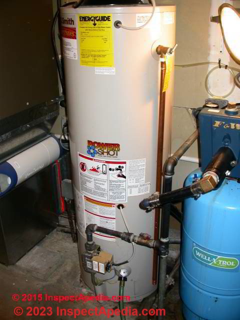
Our photo (left) shows an oil fired water heater with a T&P valve that has no discharge tube installed. There are of course other operating problems with this water heater as the photo makes clear.
TPR Valve Discharge tube blocked: Check that the discharge is not blocked by anything whatsoever. Our page top photo shows a shutoff drain valve installed at the end of a short T&P valve discharge line.
The risk is that the valve is no longer leaking not because a proper repair has been made, but because the valve has become clogged and blocked by mineral salts left behind by the evaporating hot water - leaving the installation dangerous and risking a BLEVE - explosion.
This is an unsafe condition as the operation of the temperature or pressure relief valve may be interfered with by the insulation and also because the valve cannot be inspected for evidence of leaks or failure.
Similarly, discharging a relief valve leakage or drip to a location where the leak or drip cannot be observed is a dangerous practice because the leak can go unnoticed, causing failure to recognize an unsafe condition.
TPR Valve Discharge Tube Piped "UP": the drain line must never be piped upwards in any of its course. The hazard is that the drain can become blocked or that a small drip, representing an unsafe condition at the T&P valve, may be hidden as the water simply accumulates in the bend of the trap or upwards piped section.
TPR Valve Discharge Tube Crimped, Plugged, or Reduced: the drain line may not be bent, crimped, nor plugged by any material. The diameter of the drain line may not be reduced to a size smaller than the opening of the T&P valve that it serves. Some jurisdictions may limit the number of elbows or bends permitted in the piping.
The photos above illustrates this unsafe installation practice: a 1/2" copper tube has been installed through a reducing fitting into the mouth or piping of a 3/4" diameter TPR valve.
Below the reducer from 3/4" to 1/2" was installed at the TPR valve opening. At above right a reducing elbow was used to shrink the 3/4" horizontal T&P drain line (from the TPR valve mouth) to 1/2" for the vertical run to the floor. Both of these installations are improper and unsafe.
TPR Valve Discharge Tube Active Leaking: above we show a wet floor area as well as the corroded end of the T&P discharge tube in our first photo: this relief valve is actively leaking. In this case investigation showed that the valve itself had failed - we replaced it.
TPR Valve Drain line Drip Marks: any drip stains on the floor below the valve discharge tube (second photo above ) also indicate a history of leaks at the T&P valve. Without further investigation we don"t know if this problem has been repaired or if it is simply intermittent.
TPR Valve Discharge Tube Opening is Wet: If there is corrosion on the end of the discharge tube or if you see drip stains on the floor below the drain pipe, even if the floor is dry you should always test for active or recent spillage at the relief valve. It"s possible that water on the floor has dried (on its own or with some help before a building inspection).
But if there has been recent spillage at the TPR valve the interior of the end of the discharge tube can confirm that. Using your finger, feel the inside of the tip of the discharge tube and check for water - it should be dry.
As the two photos show below, even though the floor was dry below this T&P drain line, the interior of the drain was wet - there was active leaking (or someone had recently opened the valve).
TPR Valve Discharge Tube Materials: the drain line material requirements vary by jurisdiction; some areas permit both plastic as well as copper or galvanized steel piping. But where plastic drain line materials are used, the temperature rating of the plastic must be above the highest temperature that might be produced by the heating appliance to which the T&P valve is connected.
TPR Valve Discharge Tube Termination Fittings: the end of the discharge or drain line tube should not be threaded nor fitted with any device that would permit attachment of a cap, plug, or valve that could close off the line.
TPR Valve Discharge Tube Termination Location: The water that may be discharged from a T&P valve must be conducted to a safe place of disposal. This may be a floor drain (recommended by Watts) or in some jurisdictions another location may be permitted.
Some jurisdictions do not permit the discharge drain destination to be hidden from view, on the theory that you won"t see a drip or leak and won"t thus detect an unsafe condition.
Other jurisdictions, such as in the U.K., permit the TPR valve drain line to be piped to a hidden location but require the installation of a tundish in the drain line at a suitable visible location.
The Tundish will allow the occupants to see that the TPR valve is leaking, and its air gap provides other plumbing sanitation and blockage protection features.
Outdoor terminations of a T&P valve drain line may be permitted in some jurisdictions, even required, to avoid water damage inside the building. However unless a tundish device is properly included such installations are unsafe. And piping a T&P drain line outside in freezing climates is unsafe because a dripping line may freeze and become blocked.
TPR Valve Mounting Leaks: Check for leaks around the valve where it is mounted on the boiler or boiler piping. This is a TPR valve defect, not a TPR discharge tube defect, but depending on the valve position and location, a leak around the TRP valve mount may send water (or corrosion or mineral salts) down the outside of the discharge tube, offering a valuable visual clue and possibly being mistaken for a defect in the tube itself
I am ... in the process of selling a condo I own. I got this request for repairs for the hot water heater with a picture of the heater. On the picture it shows the that the discharge line is above the TPR valve, and that this is a problem (see description on attachment). This doesn"t make any sense to me. Can you help me decide what the best action would be? thanks. - R.N. 7/11/2013
The photo is a bit difficult to read but if you look closely where the two flexible copper lines enter the wall behind the water heater, you"ll see that the smaller leftmost flexible tube, connected back to the water heater TP valve, enters the wall at a height above the valve outlet opening. What the home inspector said was perfectly correct and represents a safety hazard.
The temperature/pressure relief valve on a water heater is connected to a drain line so that if the valve opens someone nearby is not shot in the face with hot water. The discharge drain extension is typically taken to just a few inches above the floor or in some jurisdictions it may be directed outdoors - a solution that I think is risky because IF the valve should be leaking, dripping, etc., one wants to notice that and fix it to keep the system safe.
The inspector"s report makes a valid point: we should never route the discharge tube "up" from the actual outlet opening of the TP valve. That"s because if the valve should develop a small leak or be discharged on occasion, the up-routed discharge tube will keep water and debris remaining in the tube at the valve outlet where debris or mineral accumulation clog the valve or interfere with its operating spring.
The result over time could be that the valve becomes clogged and would then fail to open in a true emergency - risking, ultimately a dangerous BLEVE or water heater explosion.
Watch out: ALSO, I suspect from the photo that your water heater has a discharge tube that directs the valve outlet into a wall and going to who knows where. If the other end of that line is not already readily visible and in a location where it would be noticed, that too would be unsafe and improper.
The FIX for this unsafe condition is usually trivial: the discharge tube must be routed only "downwards" from the TP valve outlet opening, and the end of the discharge tube must be in a readily accessible, visible, and safe location. You"d probably find these same instructions in the installation manual for the water heater.
The COST for this repair should be no more than a simple plumbing service call and perhaps a few piping connections. What would make sense to me and what would be most economical would be to combine this repair with any other plumbing repairs that are needed at the home.
10. Terminate not more than 6 inches (152 mm) and not less than two times the discharge pipe diameter above the floor or waste receptor flood level rim.
14. Be one nominal size larger than the size of the relief-valve outlet, where the relief-valve discharge piping is constructed of PEX or PE-RT tubing. The outlet end of such tubing shall be fastened in place.
10. Terminate not more than 6 inches (152 mm) above and not less than two times the discharge pipe diameter above the floor or flood level rim of the waste receptor.
Some model and adopted building and plumbing codes expressly prohibit discharging the TPR valve out of the room containing the heating appliance that it is intended to protect.
1. All pressurized storage-type water heaters and unfired hot water storage tanks shall be equipped with one or more combination temperature and pressure relief valves. The temperature steam rating of a combination temperature and pressure relief valve or valves shall equal or exceed the energy input rating in BTU per hour of the water heater. No shut off valve or other restricting device may be installed between the water heater or storage tank and the combination temperature and pressure relief valve.
2. All pressurized non-storage type water heaters shall be provided with a pressure relief valve installed at the hot water outlet with no shut off valve between the heater and the relief valve.
3. Temperature and pressure relief valves shall be installed so that the sensing element of the valve extends into the heater tank and monitors the temperature in the top 6 inches of the heater or tank.
5 (e) The discharge pipe shall be installed to drain by gravity flow to a floor served by a floor drain or to a receptor in accordance with s. Comm 82.33 (8).
The outlet of the discharge pipe shall terminate within 6 inches over the floor or receptor, but not less than a distance equal to twice the diameter of the outlet pipe. The discharge pipe may not be threaded.
5 (f) The discharge pipe for a water heater shall terminate within the same room or enclosure within which the water heater or hot water storage tank is located.
WISCONSIN PLUMBING CODE, Chapter SPS 382, DESIGN, CONSTRUCTION, INSTALLATION, SUPERVISION, MAINTENANCE AND INSPECTION OF PLUMBING [PDF] (2016) retrieved 2019/11/13 original source: https://docs.legis.wisconsin.gov/code/admin_code/sps/safety_and_buildings_and_environment/380_387/382.pdf
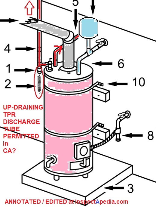
Illustrated here in a photo and sketch you can see that the relief valve drain line can, where local codes approve, be routed "up" to carry discharge across a ceiling and then down to an approved drain discharge location provided that a special draining device, shown as a spiral-wound small-diameter copper tube is attached to drain the residue water in the vertical section of the drain line after a discharge.
Later explanation from Mr. Nesbitt clarified that the copper pigtail is a small diameter "drain" intended to remove water from the vertical portion of the relief valve up-piped drain line after the valve has discharged water during an over-pressure or over-temperature or test condition.
It"s not a control nor thermocouple, it"s simply a small diameter drain. The small diameter and flow resistance of the coiled tubing causes any significant volume of TPR valve discharge to be routed up through the vertical TPR valve drain line from the tee, and the combination of tee and short copper nipple connected to the wound copper tubing are probably intended to prevent standing water or debris accumulation at the mouth of the TPR valve itself.
The pigtail drain may appear to work perfectly to drain the residing water in the vertical section of the discharge line for the relief valve at initial installation and testing, experience suggests to us that debris, especially mineral scale, is epidemic at water heater relief valves, especially if the leak at the valve is a slow drip.
Some details including the design, the pigtail connection (presumably to a shutoff control) and research supporting this up-draining valve would be helpful.
It would be useful to know what research was done to support accepting this up-draining TPR design, presumably using a temperature sensor that shuts down the boiler if hot water is found at the bottom of that tee at the TPR valve outlet.
In our OPINION that is an unsafe and questionable relief valve design in that any TPR that drains "up" is at risk of ultimately depositing mineral salts that can lead to the valve refusing to open in response to an over-temperature or over-pressure condition in the boiler, risking a catastrophic BLEVE explosion.
worse, draining the valve "up" as shown, means that a slow drip or leak won"t be discovered by visual inspection until it has leaked so long as to fill that up-sloping TPR drain that, we hope, ultimately empties at a visible location.
In our OPINION the design you show violates CA §608.5 Discharge Piping 608.5 Discharge Piping - The discharge piping serving a temperature relief valve, pressure relief valve, or combination of both shall have no valves, obstructions, or means of isolation and be provided with the following:Equal to the size of the valve outlet and shall discharge full size to the flood level of the area receiving the discharge and pointing down.
CALIFORNIA §608.3 EXPANSION TANKS, AND COMBINATION TEMPERATURE AND PRESSURE-RELIEF VALVES - retrieved 2021/11/19 original source: up.codes/viewer/california/ca-plumbing-code-2016/chapter/6/water-supply-and-distribution#608.0
CALIFORNIA §608.4 PRESSURE RELIEF VALVES retrieved 2021/11/19 original source: up.codes/viewer/california/ca-plumbing-code-2016/chapter/6/water-supply-and-distribution#608.0
A water system provided with a check valve, backflow preventer, or other normally closed device that prevents dissipation of building pressure back into the water main, independent of the type of water heater used, shall be provided with an approved, listed, and adequately sized expansion tank or other approved device having a similar function to control thermal expansion.
Such expansion tank or other approved device shall be installed on the building side of the check valve, backflow preventer, or other device and shall be sized and installed in accordance with the manufacturer"s installation instructions.
A water system containing storage water heating equipment shall be provided with an approved, listed, adequately sized combination temperature and pressure-relief valve, except for listed nonstorage instantaneous heaters having an inside diameter of not more than 3 inches (80 mm).
Each such approved combination temperature and pressure-relief valve shall be installed on the water-heating device in an approved location based on its listing requirements and the manufacturer"s installation instructions. Each such combination temperature and pressure-relief valve shall be provided with a drain in accordance with Section 608.5.
Each pressure relief valve shall be an approved automatic type with drain, and each such relief valve shall be set at a pressure of not more than 150 psi (1034 kPa). No shutoff valve shall be installed between the relief valve and the system.
The discharge piping serving a temperature relief valve, pressure relief valve, or combination of both shall have no valves, obstructions, or means of isolation and be provided with the following:
Discharge pipe shall discharge independently by gravity through an air gap into the drainage system or outside of the building with the end of the pipe not exceeding 2 feet (610 mm) and not less than 6 inches (152 mm) above the ground and pointing downwards.
A water-heating device connected to a separate storage tank and having valves between said heater and tank shall be provided with an approved water pressure relief valve.
Where a hot-water storage tank or an indirect water heater is located at an elevation above the fixture outlets in the hot-water system, a vacuum relief valve that is in accordance with CSA Z21.22 shall be installed on the storage tank or heater.
CALIFORNIA §761. SAFETY VALVES AND PRESSURE RELIEVING DEVICES, BOILERS [PDF] retrieved 2021/11/19 original source: https://www.dir.ca.gov/title8/761.html
(a) Each power boiler, nuclear boiler, and high temperature water boiler shall have safety valves or pressure relieving devices constructed, stamped and installed in accordance with the applicable section of the Code, except:
(2) Upon written request by the employer, the Division may permit three-way two-port valves to be installed under two safety valves, each with the required relieving capacity, provided they are so installed that both safety valves cannot be closed off from the boiler at the same time and provided the three-way valve will permit at least full flow to the safety valve in service at all time.
(b) The user shall maintain all pressure relieving devices in good operating condition. Where the valves cannot be tested in service, the user shall maintain and make available to the inspector records showing the test dates and set pressure for such valves.
(c) Pressure relieving devices with open discharge installations shall have piping and supports designed for pressure relief reaction forces in accordance with Appendix II of ANSI B 31.1.
I appreciate the significant convenience of being able to route a TPR valve discharge line up and thence horizontally and then "down" to a more-convenient discharge location, and now that we"ve got your added detail I understand the theory of a copper pigtail drain on the down-end of a Tee into which the water heater or boiler TPR valve is discharging.
It would be helpful to see the actual California plumbing code text on this detail and also useful to know what long-term testing and field experience have shown about the safety and reliability of this approach.
OPINION: If the small diameter pigtail drain clogs the homeowner will never know it. In normal water heater operation there should be no discharge from its TPR valve, so if later a slow drip at the valve leads to a clogged pigtail drain that condition may be indistinguishable from a perfectly functional installation.
You might detect a clogged pigtail drain on an upwards-piped relief valve drain during an annual test of the TPR valve: the valve is opened to discharge and then closed; afterwards you should see a small volume of water exiting from the pigtail drain as the remaining water in the up-piped larger diameter TPR discharge tube drains out through the pigtail.
Really? While TPR valves may come with an instruction to test the valve annually, in five decades of building inspections of thousands of buildings we have not found more than a handful of building owners who ever test a relief valve nor even know of that requirement.
In my opinion the fundamental error in ANY up-piping of ANY TPR valve is that the design is unsafe because of the possibility of accumulation of scale or other debris in that water reservoir leading to blocking of the valve"s operation when needed.
It"s a similar hazard to the one that occurs even in a down-piped TPR valve when the valve is constantly dripping or leaking. That passage of water leaves scale that ultimately blocks the valve.
Werner Sölken offers a nice explanation of these concerns. The company points out that ANY backpressure on a conventional pressure relief valve of the type commonly used on residential water heaters (disc and spring type design) will see a reduction of its opening response if there is any backpressure on the valve, such as from debris, or even from standing water in a discharge tube piped upwards (though I suspect the pressure difference in most buildings would be small).
Excerpt: A conventional safety Relief Valve is a pressure Relief Valve which has its spring housing vented to the discharge side of the Valve. The operational characteristics (opening pressure, closing pressure, and relieving capacity) are directly affected by changes of the back pressure on the Valve."
Allied Valve raises another objection that may pertain to your up-piped relief valve discharge piping: possible loading on the valve body itself if the piping does not support its own weight.
Allied Valve, 3 THINGS TO AVOID WHEN INSTALLING & OPERATING SAFETY VALVES [PDF] Allied Valve, 4119 State St., Riverdale IA, 52722 Tel: 800-827-1197 Web: alliedvalveinc.com - retrieved 2022/01/12 original source: https://alliedvalveinc.com/the-valve-expert/3-things-avoid-installing-operating-safety-valves/
Excerpt: "Stress from Improperly-supported discharge piping" Discharge piping must be installed so that it supports its own weight and does not put any weight or strain on the valve itself. According to the National Board of Boiler and Pressure Vessel Inspectors, improperly supported discharge piping is one of the top problems that can prevent valves from operating normally.
Discharge piping connected to the device must be supported so as not to impart any loadings on the body of the device. These loadings could affect or prevent the proper operation of the device including proper reclosure after operating
In sum, a relief valve discharge tube that is not pointing downwards may become unsafe. I agree that the worst does not always happen; if it did there would be no doubters. But the risk of a BLEVE explosion and the results of such a blast are so serious as to be considered carefully.
TPR valves drip far more often than they flow at volume. Slow drips easily leave scale that can clog a 1/8" diameter spiral tube with crimped end pretty quickly.
Then this and another pressure relief valve on a furnace boiler were overlooked for code violations in an official inspection--which I arranged--which took all of five minutes.
They don"t seem to care to look as closely at things like temperature and pressure relief valves as your inspection website does--but I wish.
The relief valve discharge tube is down-sized, smaller than the opening of the relief valve itself, reducing the valve"s ability to release heat, pressure, energy, should the heater over-heat
There is a drop of water at the discharge tube mouth that may be telling us that this valve leaks - which risks valve clogging by mineral scale and again risking that it cannot work safely if called-on to do so.
Incidentally, that water heater insulation is not required and in some installations can be itself unsafe, e.g. if it blocks view of or draining of a relief valve.
"Red tagging" is most-often done by a service technician. Others (building code inspector or home inspector) should write up the issue, and because it"s a life-safety concern, ought to notify all parties concerned, including owners and occupants of the building - in writing and orally.
The TPR valve needs to be installed in a tapping on the heater itself, near the top or on the top, as provided by the manufacturer; if you give the brand and model of water heater we may be able to find the installation manual that will show those exact details.
Watch out: a TPR valve not properly located risks failing to respond adequately to over-temperature or over-pressure in the water heater, risking a BLEVE explosion.
Watch out: Looking again at your photo it looks to me as if the TPR valve is connected to a pipe that goes "up" to some unknown destination or "down" to a valve that is closed; this is an unsafe and dangerous and incorrect installation.
Practically, you have to have enough space that when replacement of the TPR valve is needed there is working space to unscrew and remove the old one and get the new one in place - that might be just an inch or two past the test lever; and separately, you don"t want any dripping or discharge to wet the drywall lest you invite a mold contamination issue.
Practically - adding another messy detail, if your water heater sits in a drip or spill tray then the bottom of the discharge pipe will have to jog out and over and down to get past the outer edge of the drip tray, so the drip tray itself is going to space the heater and most of the discharge pipe a bit more-distant from the wall.
For example this gas fueled American Standard water heater - just an EXAMPLE - your heater may differ, lets the heater itself be as close as 2 inches from a wall, but that does NOT consider space to get the TPR valve on and off.
Take a look at where the TPR valve is connected to your water heater; if it"s on a side (near the top of course) then you need working space for the valve.
If the TPR valve is connected off of a tapping on the top of the water heater (as is on some models) then there"s probably plenty of working space there and the discharge tube could be quite close to the wall - but considering the practical warnings I gave above.
Above is an illustration of an [American Standard] electric water heater installed with a drain pan - notice the relief valve discharge pipe routing.
Even though the discharge of water into an area may not, in your opinion, cause damage to the building, the point of discharge must be visible so that someone can spot trouble (leaks) before a catastrophe occurs
Your local building code inspector might indeed approve routing the relief valve discharge to a hidden and harmless location provided a Tundish is installed so that leaks can be detected.
Would it be acceptable to allow the T&P valve to simply dump into the crushed rock in the crawl space? Could the same be done with the condensate line?
It is common to see plastic discharge tubes on some PT valves and that"s an accepted practice provided the tubing is properly rated for the temperatures involved.
As you can see from the example I give below, a typical residential boiler relief valve costs less than $100. U.S. and a typical discharge tube of 3 or 4 feet or less costs less than $10. U.S.
Even if a plumber charged a minimum of an hour"s labor to unscrew the old valve and screw in the new one and its discharge tube that ought not amount to a substantial total (where I read "substantial" as hundreds of dollars) unless there was something rather unusual and costly going on in your home.
Recently we replaced our 14 year old Ultra 310 Boiler with a new Evergreen 399 Boiler. Our Ultra 310 boiler was professionally installed with a plastic PT valve a white plastic discharge tube. During a routine maintenance,
We now have a new Evergreen Boiler and the copper was removed and replaced with a blue plastic discharge tube. So, which should it be? We are puzzled.
There is water FLOWING from the DISCHARGE TUBE on my Triangle Tube, indirect fired water heater. (I shut of the water supply off to the tank so it isn"t spilling onto the floor.) Does this suggest that I need to replace the T&P relief valve?
Hi there just wondering why my TPR doesn"t discharge at all and i tested it by lifting the lever and it was flowing freely outside and stopped when i released it back?Is that normal?Thanks
I have a relief valve right on top of my steam boiler, it doesn"t have a discharge outlet but it has openings right on top of it where i see some, if not too much steam coming out, it should be replaced or it is normal?
Possibly. But it"s easy to check. Compare the actual boiler pressure when leaks are seen with the valve rating. Normally a hydronic heating boiler doesn"t run over 30 psi
Fillip, the valve should not be leaking, but before replacing it you need to know why it"s leaky, as the problem may not be the valve. Call your service company as this is va safety concern
Thanks for the information. Is there any requirement that the fitting and pipe extension is required to be made from copper? I came across a boiler where the fitting off the T&P and the extension to the floor is made of PVC. - Kevin 7/26/2011
Kevin the relief valve would itself tap into a metal fitting on the boiler or on older installations on metal heating piping. But the discharge tube on many new installations is plastic; it"s a pipe that rarely sees service and whose job is to divert hot water to the floor rather than onto a bystander. In that application most code officials accept PVC.
My new tankless water heater is in a place in my basement (finished) where there is no floor drain. A sump pit and pump exist in the area. Obviously if my relief valve activates, if it were to just be allowed to dump onto the floor, the water would travel through a finished part of my basement before reaching the drain.
Right now I have a piece of plastic tubing attached to the bottom of the 3/4" relief valve pipe. This is probably not the best or legal solution but it would keep my basement from flooding (so long as sump pump operates.) Is there a legal option of looping the relief valve discharge tube up through the band board of my house so it can drain to the outside?
Do not pipe the TP valve discharge tube UP - the result (because dripping or leaks can remain in the piping and valve opening) can be a clogged, failed TP valve and a fatal BLEVE explosion.
In a photo above on this page you can see a flexible 3/4" copper tube used in the routing of the discharge of a TP valve from the top of a water heater. No one called out the use of that piping material itself as a hazard, but there can be hazards nonetheless depending on how that tube is routed - such as to a hidden location without a Tundish or routed "up" from the TP valve itself.
So ... it depends. If for example someone installed a flexible line to replace a straight downtube running down the side of a water heater from the TP valve, I"d be worried that some fool would come along and bend the tubing "up" - as nothing prevents them from doing so. Maybe to get it out of the way of a basketball or something. The result is a dangerous blockage of the TP valve and the risk of a BLEVE explosion. SO if I I were a building inspector given final authority I"d object to that installation. But I might not object to use of the same tubing connecting properly between a valve"s discharge opening and a proper destination.
Discharge line must always be installed to avoid water damage and scalding injury, when valve operates. Discharge line must be same size as valve outlet, be pitched down for free draining, and have no shut-off valve or obstructions throughout its entire length. Discharge line termination point should be visible to observe any discharge.
2. it is not permissible to terminate a TPR valve discharge line with a threaded fitting - the reasoning is that it"s too easy for someone to screw a cap onto a dripping line, leading ultimately to a BLEVE explosion.
RELIEF VALVE DISCHARGE TUBE at InspectApedia.com - online encyclopedia of building & environmental inspection, testing, diagnosis, repair, & problem prevention advice.
phone (610) 252-7355, original source http://www.harvel.com/piping-systems/gf-harvel-cpvc-industrial-pipe, copy on file as GF_CPVC Industrial Pipe _ CPVC Pipe.pdf.
(Model BR4EC - Water Pressure Reducing Valve With Thermal Expansion Relief Valve … Discontinued Products,Pressure Reducing Valves,Wilkins Water Control,,R4EC,4EC)
[6] A.O. Smith"s Form No. 4778* All about Deliming Coil-Type/Tube-Type Commercial Water Heaters and Hydronic Boilers *Normally supplied when ordering Part No. 4930 Motorized Deliming Pump Kit
[7] "Building Owner Water Heater Safety Notice", Building Department, City of Colleyville TX, web search 09/24/2010, original source: http://www.colleyville.com/dmdocuments/Building%20
Water heater safety is imperative to the occupants of a building or structure. If improperly installed, water heaters can be detrimental to the structure, as well as being potentially fatal to its occupants. The proper installation of a water heater is so important that according to Texas State Law all water heater installations must be inspected by a state licensed plumbing inspector.
[9] Watts, 815 Chestnut Street, North Andover, MA, USA 01845-6098, web search 09/18/2010 original source: http://www.watts.com/pages/learnAbout/reducingValves.asp?catId=64
In small scale testing, the Mythbusters started with a small six gallon water heater and disabled all of its safety features under the theory of poor installation or neglect. While the water heater eventually ruptured, it did not explode like a rocket. The Mythbusters then upgraded to larger thirty gallon water heater which exploded with significantly greater force, sending the water heater several hundred feet into the air. In order to confirm the stated myth, the Mythbusters obtained a full size fifty two gallon water heater and built a shack around it with a roof that followed standard California building codes. The water heater eventually exploded, shooting through the roof five hundred feet into the air and disintegrating the shack. In light of these results, and the fact that there is documented evidence corroborating the myth, the Mythbusters deemed it confirmed.
Because of built in safety devices most water heaters safely operate day in, day out without any major problems. But don"t let the excellent safety record of water heaters lull you into forgetting about the explosive potential of these marvels of convenience. When a water heater explodes, it releases a tremendous blast force which can easily demolish a building.
Randall Hilton and crew, with help from the Service Roundtable has prepared this video of a water heater explosion as a demonstration of the explosive power of a simple water heater. The hot water tank explodes using the steam pressure that any water heater can generate when the thermostat and temperature pressure relief valve (T&P valve or PT valve) malfunction. We were impressed by how far the tank flew after the water heater exploded. Click on the links below to view the video. Then, visit the Q&A page for warning signs as well as simple steps which can help you prevent your own water heater from exploding.
TECHNICAL REFERENCE GUIDE to manufacturer"s model and serial number information for heating and cooling equipment, useful for determining the age of heating boilers, furnaces, water heaters is provided by Carson Dunlop Weldon & Associates
Safety valves are an arrangement or mechanism to release a substance from the concerned system in the event of pressure or temperature exceeding a particular preset limit. The systems in the context may be boilers, steam boilers, pressure vessels or other related systems. As per the mechanical arrangement, this one get fitted into the bigger picture (part of the bigger arrangement) called as PSV or PRV that is pressure safety or pressure relief valves.
This type of safety mechanism was largely implemented to counter the problem of accidental explosion of steam boilers. Initiated in the working of a steam digester, there were many methodologies that were then accommodated during the phase of the industrial revolution. And since then this safety mechanism has come a long way and now accommodates various other aspects.
These aspects like applications, performance criteria, ranges, nation based standards (countries like United States, European Union, Japan, South Korea provide different standards) etc. manage to differentiate or categorize this safety valve segment. So, there can be many different ways in which these safety valves get differentiated but a common range of bifurcation is as follows:
The American Society of Mechanical Engineers (ASME) I tap is a type of safety valve which opens with respect to 3% and 4% of pressure (ASME code for pressure vessel applications) while ASME VIII valve opens at 10% over pressure and closes at 7%. Lift safety valves get further classified as low-lift and full lift. The flow control valves regulate the pressure or flow of a fluid whereas a balanced valve is used to minimize the effects induced by pressure on operating characteristics of the valve in context.
A power operated valve is a type of pressure relief valve is which an external power source is also used to relieve the pressure. A proportional-relief valve gets opened in a relatively stable manner as compared to increasing pressure. There are 2 types of direct-loaded safety valves, first being diaphragms and second: bellows. diaphragms are valves which spring for the protection of effects of the liquid membrane while bellows provide an arrangement where the parts of rotating elements and sources get protected from the effects of the liquid via bellows.
In a master valve, the operation and even the initiation is controlled by the fluid which gets discharged via a pilot valve. Now coming to the bigger picture, the pressure safety valves based segment gets classified as follows:
So all in all, pressure safety valves, pressure relief valves, relief valves, pilot-operated relief valves, low pressure safety valves, vacuum pressure safety valves etc. complete the range of safety measures in boilers and related devices.
Safety valves have different discharge capacities. These capacities are based on the geometrical area of the body seat upstream and downstream of the valve. Flow diameter is the minimum geometrical diameter upstream and downstream of the body seat.
The nominal size designation refers to the inlet orifice diameter. A safety Valve"s theoretical flowing capacity is the mass flow through an orifice with the same cross-sectional area as the valve"s flow area. This capacity does not account for the flow losses caused by the valve. The actual capacity is measured, and the certified flow capacity is the actual flow capacity reduced by 10%.
A safety valve"s discharge capacity is dependent on the set pressure and position in a system. Once the set pressure is calculated, the discharge capacity must be determined. Safety valves may be oversized or undersized depending on the flow throughput and/or the valve"s set pressure.
The actual discharge capacity of a safety valve depends on the type of discharge system used. In liquid service, safety valves are generally automatic and direct-pressure actuated.
A safety valve is used to protect against overpressure in a fluid system. Its design allows for a lift in the disc, indicating that the valve is about to open. When the inlet pressure rises above the set pressure, the guide moves to the open position, and media flows to the outlet via the pilot tube. Once the inlet pressure falls below the set pressure, the main valve closes and prevents overpressure. There are five criteria for selecting a safety valve.
The first and most basic requirement of a safety valve is its ability to safely control the flow of gas. Hence, the valve must be able to control the flow of gas and water. The valve should be able to withstand the high pressures of the system. This is because the gas or steam coming from the boiler will be condensed and fill the pipe. The steam will then wet the safety valve seat.
The other major requirement for safety valves is their ability to prevent pressure buildup. They prevent overpressure conditions by allowing liquid or gas to escape. Safety valves are used in many different applications. Gas and steam lines, for example, can prevent catastrophic damage to the plant. They are also known as safety relief valves. During an emergency, a safety valve will open automatically and discharge gas or liquid pressure from a pressurized system, preventing it from reaching dangerous levels.
The discharge capacity of a safety valve is based on its orifice area, set pressure, and position in the system. A safety valve"s discharge capacity should be calculated based on the maximum flow through its inlet and outlet orifice areas. Its nominal size is often determined by manufacturer specifications.
Its discharge capacity is the maximum flow through the valve that it can relieve, based on the maximum flow through each individual flow path or combined flow path. The discharge pressure of the safety valve should be more than the operating pressure of the system. As a thumb rule, the relief pressure should be 10% above the working pressure of the system.
It is important to choose the discharge capacity of a safety valve based on the inlet and output piping sizes. Ideally, the discharge capacity should be equal to or greater than the maximum output of the system. A safety valve should also be installed vertically and into a clean fitting. While installing a valve, it is important to use a proper wrench for installation. The discharge piping should slope downward to drain any condensate.
The discharge capacity of a safety valve is measured in a few different ways. The first is the test pressure. This gauge pressure is the pressure at which the valve opens, while the second is the pressure at which it re-closes. Both are measured in a test stand under controlled conditions. A safety valve with a test pressure of 10,000 psi is rated at 10,000 psi (as per ASME PTC25.3).
The discharge capacity of a safety valve should be large enough to dissipate a large volume of pressure. A small valve may be adequate for a smaller system, but a larger one could cause an explosion. In a large-scale manufacturing plant, safety valves are critical for the safety of personnel and equipment. Choosing the right valve size for a particular system is essential to its efficiency.
Before you use a safety valve, you need to know its discharge capacity. Here are some steps you need to follow to calculate the discharge capacity of a safety valve.
To check the discharge capacity of a safety valve, the safety valve should be installed in the appropriate location. Its inlet and outlet pipework should be thoroughly cleaned before installation. It is important to avoid excessive use of PTFE tape and to ensure that the installation is solid. The safety valve should not be exposed to vibration or undue stress. When mounting a safety valve, it should be installed vertically and with the test lever at the top. The inlet connection of the safety valve should be attached to the vessel or pipeline with the shortest length of pipe. It must not be interrupted by any isolation valve. The pressure loss at the inlet of a safety valve should not exceed 3% of the set pressure.
The sizing of a safety valve depends on the amount of fluid it is required to control. The rated discharge capacity is a function of the safety valve"s orifice area, set pressure, and position in the system. Using the manufacturer"s specifications for orifice area and nominal size of the valve, the capacity of a safety valve can be determined. The discharge flow can be calculated using the maximum flow through the valve or the combined flows of several paths. When sizing a safety valve, it"s necessary to consider both its theoretical and actual discharge capacity. Ideally, the discharge capacity will be equal to the minimum area.
To determine the correct set pressure for a safety valve, consider the following criteria. It must be less than the MAAP of the system. Set pressure of 5% greater than the MAAP will result in an overpressure of 10%. If the set pressure is higher than the MAAP, the safety valve will not close. The MAAP must never exceed the set pressure. A set pressure that is too high will result in a poor shutoff after discharge. Depending on the type of valve, a backpressure variation of 10% to 15% of the set pressure cannot be handled by a conventional valve.
Discharge pipe shall discharge independently by gravity through an air gap into the drainage system or outside of the building with the end of the pipe not exceeding 2 feet (610 mm) and not less than 6 inches (152 mm) above the ground and pointing downwards.
The ASME Boiler and Pressure Vessel Code and publications by many manufacturers caution the design engineer to consider back pressure in discharge piping when sizing and selecting pressure relief valves. Only general guidelines are given, however, because of widely varying installation requirements. This paper addresses manifolded discharge piping system design. The method of analysis provides a simple technique for determining pressure within a discharge piping system. The method is based on adiabatic flow and uses local Mach number to relate expansion of the gas in the pipes to a mass flow function. The paper illustrates that relief valves discharging into lines and headers should not be sized or selected without careful analysis of the entire relief system.

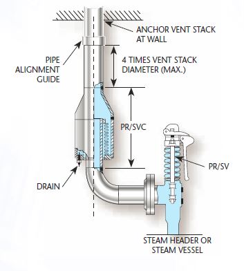
Dante Valve recommends the use of a Drip Pan Elbow in conjunction with a steam service safety valve. Drip Pan Elbows can prevent injury and damage to people, equipment or supplies located near the safety valve or discharge piping. When attached to a safety valve outlet, the Drip Pan Elbow collects, removes and returns condensate to safe areas, and isolates the valve from discharge piping stresses. This keeps the safety valve from filling with water.
Drip Pan Elbows also help improve the performance and longevity of the safety valve by alleviating axial loads, preventing defective operations and shut-off. Drip Pan Elbows are compatible with all ASME safety valves and are easily installed on female NPT or flanged outlets.
Dante Valve offers Drip Pan Elbows featuring consistently high quality workmanship and materials. We stock all sizes 3/4″ through 10″ for immediate delivery.
A boiler valve kit is a must-have for any homeowner with a boiler system. This brass valve kit features a vent safety valve that helps to protect your home from dangerous gas build-up. The included instructions make installation easy, and the durable brass construction ensures lasting performance. Keep your family safe with this essential boiler valve kit.
9. When the calibrated pressure is reached, the valve opens automatically and discharges the atmosphere to protect the whole system from safe caused by overpressure
10. This brass boiler valve kit is perfect for any steam-powered project. The kit includes a pressure gauge, safety valve, and two shut-off valves. The pressure gauge helps you monitor the pressure in your boiler, the safety valve keeps your boiler from exploding, and the shut-off valves let you turn off the steam supply without having to drain the boiler.
This brass boiler valve kit is perfect for any steam-related projects you may have. It includes a durable boiler and vent safety valve to keep your project safe and functional. The included instructions make it easy to install this kit in no time. This boiler valve kit is the perfect addition to your tool collection with its high-quality construction and affordable price. This brass boiler valve kit is ideal for any steam-based appliance. The kit includes a boiler valve, vent safety valve, and all the necessary fittings for a quick and easy installation. The included vent safety valve helps to ensure safe operation by releasing excess pressure in the event of a malfunction. This kit is ideal for use with any boiler, including cast iron, steel, or copper boilers.
Vent safety valves are required for all direct-fired appliances; this kit includes everything you need to install one. The boiler valve is brass and has a 1/2-inch pipe thread fitting that can be connected to the vent pipe. It also features an adjustable pressure relief valve with a gauge, protecting your home from high-pressure steam or air from the system. This kit comes with two elbows (1 in., two in.), four nipples (3/4 in., 1/8 in., 3/8 in.), three straight fittings (5/16 inches), and five pipe connectors (3 ways).
This boiler kit includes a brass pressure relief valve with an air vent, which is required by law. It also has a 1/2″ discharge elbow and two unions connecting the pipe inlet to your water heater. The safety valves are designed to prevent excess pressure from building up inside the tank, which can cause dangerous boil-overs or even potential explosions. This kit is excellent for homeowners with existing water heaters without this equipment installed.
Tired of keeping track of your valve inventory’s annual certification records? We offer complete management of your safety relief valves. With an inventory of repair parts and in stock relief valves of all sizes, we can respond to any customer emergency. We offer annual certification services as well as repair of all major brands, including Kunkle, Conbraco, Consolidated, Dresser, Apollo and more.

In the latter half of the 19th century explosions of steam boilers were commonplace. As a consequence of this, a company was formed in Manchester with the objective of reducing the number of explosions by subjecting steam boilers to independent examination. This company was, in fact, the beginning of today’s Safety Federation (SAFed), the body whose approval is required for boiler controls and fittings in the UK.
After a comparatively short period, only eight out of the 11 000 boilers examined exploded. This compared to 260 steam boiler explosions in boilers not examined by the scheme. This success led to the Boiler Explosions Act (1882) which included a requirement for a boiler name-plate. An example of a boiler name-plate is shown in Figure 3.7.1.
The serial number and model number uniquely identify the boiler and are used when ordering spares from the manufacturer and in the main boiler log book.
In Europe, matters relating to the suitability of safety valves for steam boilers are governed by the European standard EN 12953. In the US and some other parts of the world, such matters are covered by ASME standards.
The total discharge capacity of the safety valve(s) must be at least equal to the ‘from and at 100°C’ capacity of the boiler. If the ‘from and at’ evaporation is used to size the safety valve, the safety valve capacity will always be higher than the actual maximum evaporative boiler capacity.
The discharge pipework from the safety valve must be unobstructed and drained at the base to prevent the accumulation of condensate. It is good practice to ensure that the discharge pipework is kept as short as possible with the minimum number of bends, so that the allowable backpressure indicated by the valve manufacturer is not exceeded.
It will be quite normal for the internal diameter of the discharge pipework to be more than the internal diameter of the safety valve outlet connection, but under no circumstances should it be less.
A steam boiler must be fitted with a stop valve (also known as a crown valve) which isolates the steam boiler and its pressure from the process or plant. It is generally an angle pattern globe valve of the screw-down variety. Figure 3.7.3 shows a typical stop valve of this type.
In the past, these valves have often been manufactured from cast iron, with steel and bronze being used for higher pressure applications. In the UK, BS 2790 (eventually to be replaced with EN 12953) states that cast iron valves are no longer permitted for this application on steam boilers. Nodular or spheroidal graphite (SG) iron should not be confused with grey cast iron as it has mechanical properties approaching those of steel. For this reason many boilermakers use SG iron valves as standard.
The stop valve is not designed as a throttling valve, and should be fully open or closed. It should always be opened slowly to prevent any sudden rise in downstream pressure and associated waterhammer, and to help restrict the fall in boiler pressure and any possible associated priming.
To comply with UK regulations, the valve should be of the ‘rising handwheel’ type. This allows the boiler operator to easily see the valve position, even from floor level. The valve shown is fitted with an indicator that makes this even easier for the operator.
On multi-boiler applications an additional isolating valve should be fitted, in series with the crown valve. At least one of these valves should be lockable in the closed position. The additional valve is generally a globe valve of the screw-down, non-return type which prevents one boiler pressurising another. Alternatively, it is possible to use a screw-down valve, with a disc check valve sandwiched between the flanges of the crown valve and itself.
The feedwater check valve (as shown in Figures 3.7.4 and 3.7.5) is installed in the boiler feedwater line between the feedpump and boiler. A boiler feed stop valve is fitted at the boiler shell.
The check valve includes a spring equivalent to the head of water in the elevated feedtank when there is no pressure in the boiler. This prevents the boiler being flooded by the static head from the boiler feedtank.
Under normal steaming conditions the check valve operates in a conventional manner to stop return flow from the boiler entering the feedline when the feedpump is not running. When the feedpump is running, its pressure overcomes the spring to feed the boiler as normal.
Because a good seal is required, and the temperatures involved are relatively low (usually less than 100°C) a check valve with a EPDM (Ethylene Propylene) soft seat is generally the best option.
The maintenance of water quality is essential to the safe and efficient operation of a steam boiler. The measurement and control of the various parameters is a complex topic, which is also covered by a number of regulations. It is therefore covered in detail later in this Block. The objective of the next few Sections is simply to identify the fittings to be seen on a boiler.
This controls the amount of Total Dissolved Solids (TDS) in the boiler water, and is sometimes also referred to as ‘continuous blowdown’. The boiler connection is typically DN15 or DN20. The system may be manual or automatic. Whatever system is used, the TDS in a sample of boiler water is compared with a set point; if the TDS level is too high, a quantity of boiler water is released to be replaced by feedwater with a much lower TDS level. This has the effect of diluting the water in the boiler, and reducing the TDS level.
This ejects the sludge or sediment from the bottom of the boiler. The control is a large (usually DN25 to DN50) key operated valve. This valve might normally be opened for a period of about 5 seconds, once per shift.
Figure 3.7.7 illustrates a key operated manual bottom blowdown valve whereas Figure 3.7.8 illustrates an automated bottom blowdown valve and its typical position in a blowdown system.
Pressure g


 8613371530291