
boiler safety valve lifting pressure in stock
In order to ensure that the maximum allowable accumulation pressure of any system or apparatus protected by a safety valve is never exceeded, careful consideration of the safety valve’s position in the system has to be made. As there is such a wide range of applications, there is no absolute rule as to where the valve should be positioned and therefore, every application needs to be treated separately.
A common steam application for a safety valve is to protect process equipment supplied from a pressure reducing station. Two possible arrangements are shown in Figure 9.3.3.
The safety valve can be fitted within the pressure reducing station itself, that is, before the downstream stop valve, as in Figure 9.3.3 (a), or further downstream, nearer the apparatus as in Figure 9.3.3 (b). Fitting the safety valve before the downstream stop valve has the following advantages:
• The safety valve can be tested in-line by shutting down the downstream stop valve without the chance of downstream apparatus being over pressurised, should the safety valve fail under test.
• When setting the PRV under no-load conditions, the operation of the safety valve can be observed, as this condition is most likely to cause ‘simmer’. If this should occur, the PRV pressure can be adjusted to below the safety valve reseat pressure.
Indeed, a separate safety valve may have to be fitted on the inlet to each downstream piece of apparatus, when the PRV supplies several such pieces of apparatus.
• If supplying one piece of apparatus, which has a MAWP pressure less than the PRV supply pressure, the apparatus must be fitted with a safety valve, preferably close-coupled to its steam inlet connection.
• If a PRV is supplying more than one apparatus and the MAWP of any item is less than the PRV supply pressure, either the PRV station must be fitted with a safety valve set at the lowest possible MAWP of the connected apparatus, or each item of affected apparatus must be fitted with a safety valve.
• The safety valve must be located so that the pressure cannot accumulate in the apparatus viaanother route, for example, from a separate steam line or a bypass line.
It could be argued that every installation deserves special consideration when it comes to safety, but the following applications and situations are a little unusual and worth considering:
• Fire - Any pressure vessel should be protected from overpressure in the event of fire. Although a safety valve mounted for operational protection may also offer protection under fire conditions,such cases require special consideration, which is beyond the scope of this text.
• Exothermic applications - These must be fitted with a safety valve close-coupled to the apparatus steam inlet or the body direct. No alternative applies.
• Safety valves used as warning devices - Sometimes, safety valves are fitted to systems as warning devices. They are not required to relieve fault loads but to warn of pressures increasing above normal working pressures for operational reasons only. In these instances, safety valves are set at the warning pressure and only need to be of minimum size. If there is any danger of systems fitted with such a safety valve exceeding their maximum allowable working pressure, they must be protected by additional safety valves in the usual way.
In order to illustrate the importance of the positioning of a safety valve, consider an automatic pump trap (see Block 14) used to remove condensate from a heating vessel. The automatic pump trap (APT), incorporates a mechanical type pump, which uses the motive force of steam to pump the condensate through the return system. The position of the safety valve will depend on the MAWP of the APT and its required motive inlet pressure.
This arrangement is suitable if the pump-trap motive pressure is less than 1.6 bar g (safety valve set pressure of 2 bar g less 0.3 bar blowdown and a 0.1 bar shut-off margin). Since the MAWP of both the APT and the vessel are greater than the safety valve set pressure, a single safety valve would provide suitable protection for the system.
However, if the pump-trap motive pressure had to be greater than 1.6 bar g, the APT supply would have to be taken from the high pressure side of the PRV, and reduced to a more appropriate pressure, but still less than the 4.5 bar g MAWP of the APT. The arrangement shown in Figure 9.3.5 would be suitable in this situation.
Here, two separate PRV stations are used each with its own safety valve. If the APT internals failed and steam at 4 bar g passed through the APT and into the vessel, safety valve ‘A’ would relieve this pressure and protect the vessel. Safety valve ‘B’ would not lift as the pressure in the APT is still acceptable and below its set pressure.
It should be noted that safety valve ‘A’ is positioned on the downstream side of the temperature control valve; this is done for both safety and operational reasons:
Operation - There is less chance of safety valve ‘A’ simmering during operation in this position,as the pressure is typically lower after the control valve than before it.
Also, note that if the MAWP of the pump-trap were greater than the pressure upstream of PRV ‘A’, it would be permissible to omit safety valve ‘B’ from the system, but safety valve ‘A’ must be sized to take into account the total fault flow through PRV ‘B’ as well as through PRV ‘A’.
A pharmaceutical factory has twelve jacketed pans on the same production floor, all rated with the same MAWP. Where would the safety valve be positioned?
One solution would be to install a safety valve on the inlet to each pan (Figure 9.3.6). In this instance, each safety valve would have to be sized to pass the entire load, in case the PRV failed open whilst the other eleven pans were shut down.
If additional apparatus with a lower MAWP than the pans (for example, a shell and tube heat exchanger) were to be included in the system, it would be necessary to fit an additional safety valve. This safety valve would be set to an appropriate lower set pressure and sized to pass the fault flow through the temperature control valve (see Figure 9.3.8).

As soon as mankind was able to boil water to create steam, the necessity of the safety device became evident. As long as 2000 years ago, the Chinese were using cauldrons with hinged lids to allow (relatively) safer production of steam. At the beginning of the 14th century, chemists used conical plugs and later, compressed springs to act as safety devices on pressurised vessels.
Early in the 19th century, boiler explosions on ships and locomotives frequently resulted from faulty safety devices, which led to the development of the first safety relief valves.
In 1848, Charles Retchie invented the accumulation chamber, which increases the compression surface within the safety valve allowing it to open rapidly within a narrow overpressure margin.
Today, most steam users are compelled by local health and safety regulations to ensure that their plant and processes incorporate safety devices and precautions, which ensure that dangerous conditions are prevented.
The principle type of device used to prevent overpressure in plant is the safety or safety relief valve. The safety valve operates by releasing a volume of fluid from within the plant when a predetermined maximum pressure is reached, thereby reducing the excess pressure in a safe manner. As the safety valve may be the only remaining device to prevent catastrophic failure under overpressure conditions, it is important that any such device is capable of operating at all times and under all possible conditions.
Safety valves should be installed wherever the maximum allowable working pressure (MAWP) of a system or pressure-containing vessel is likely to be exceeded. In steam systems, safety valves are typically used for boiler overpressure protection and other applications such as downstream of pressure reducing controls. Although their primary role is for safety, safety valves are also used in process operations to prevent product damage due to excess pressure. Pressure excess can be generated in a number of different situations, including:
The terms ‘safety valve’ and ‘safety relief valve’ are generic terms to describe many varieties of pressure relief devices that are designed to prevent excessive internal fluid pressure build-up. A wide range of different valves is available for many different applications and performance criteria.
In most national standards, specific definitions are given for the terms associated with safety and safety relief valves. There are several notable differences between the terminology used in the USA and Europe. One of the most important differences is that a valve referred to as a ‘safety valve’ in Europe is referred to as a ‘safety relief valve’ or ‘pressure relief valve’ in the USA. In addition, the term ‘safety valve’ in the USA generally refers specifically to the full-lift type of safety valve used in Europe.
Pressure relief valve- A spring-loaded pressure relief valve which is designed to open to relieve excess pressure and to reclose and prevent the further flow of fluid after normal conditions have been restored. It is characterised by a rapid-opening ‘pop’ action or by opening in a manner generally proportional to the increase in pressure over the opening pressure. It may be used for either compressible or incompressible fluids, depending on design, adjustment, or application.
Safety valves are primarily used with compressible gases and in particular for steam and air services. However, they can also be used for process type applications where they may be needed to protect the plant or to prevent spoilage of the product being processed.
Relief valve - A pressure relief device actuated by inlet static pressure having a gradual lift generally proportional to the increase in pressure over opening pressure.
Relief valves are commonly used in liquid systems, especially for lower capacities and thermal expansion duty. They can also be used on pumped systems as pressure overspill devices.
Safety relief valve - A pressure relief valve characterised by rapid opening or pop action, or by opening in proportion to the increase in pressure over the opening pressure, depending on the application, and which may be used either for liquid or compressible fluid.
In general, the safety relief valve will perform as a safety valve when used in a compressible gas system, but it will open in proportion to the overpressure when used in liquid systems, as would a relief valve.
Safety valve- A valve which automatically, without the assistance of any energy other than that of the fluid concerned, discharges a quantity of the fluid so as to prevent a predetermined safe pressure being exceeded, and which is designed to re-close and prevent further flow of fluid after normal pressure conditions of service have been restored.

Years ago, it was not uncommon to read news about tragic boiler explosions, sometimes resulting in mass destruction. Today, boilers are equipped with important safety devises to help protect against these types of catastrophes. Let’s take a look at the most critical of these devices: the safety valve.
The safety valve is one of the most important safety devices in a steam system. Safety valves provide a measure of security for plant operators and equipment from over pressure conditions. The main function of a safety valve is to relieve pressure. It is located on the boiler steam drum, and will automatically open when the pressure of the inlet side of the valve increases past the preset pressure. All boilers are required by ASME code to have at least one safety valve, dependent upon the maximum flow capacity (MFC) of the boiler. The total capacity of the safety valve at the set point must exceed the steam control valve’s MFC if the steam valve were to fail to open. In most cases, two safety valves per boiler are required, and a third may be needed if they do not exceed the MFC.
There are three main parts to the safety valve: nozzle, disc, and spring. Pressurized steam enters the valve through the nozzle and is then threaded to the boiler. The disc is the lid to the nozzle, which opens or closes depending on the pressure coming from the boiler. The spring is the pressure controller.
As a boiler starts to over pressure, the nozzle will start to receive a higher pressure coming from the inlet side of the valve, and will start to sound like it is simmering. When the pressure becomes higher than the predetermined pressure of the spring, the disc will start to lift and release the steam, creating a “pop” sound. After it has released and the steam and pressure drops below the set pressure of the valve, the spring will close the disc. Once the safety valve has popped, it is important to check the valve to make sure it is not damaged and is working properly.
A safety valve is usually referred to as the last line of safety defense. Without safety valves, the boiler can exceed it’s maximum allowable working pressure (MAWP) and not only damage equipment, but also injure or kill plant operators that are close by. Many variables can cause a safety valve on a boiler to lift, such as a compressed air or electrical power failure to control instrumentation, or an imbalance of feedwater rate caused by an inadvertently shut or open isolation valve.
Once a safety valve has lifted, it is important to do a complete boiler inspection and confirm that there are no other boiler servicing issues. A safety valve should only do its job once; safety valves should not lift continuously. Lastly, it is important to have the safety valves fully repaired, cleaned and recertified with a National Board valve repair (VR) stamp as required by local code or jurisdiction. Safety valves are a critical component in a steam system, and must be maintained.
All of Nationwide Boiler’s rental boilers include on to two safety valves depending on the size; one set at design pressure and the other set slightly higher than design. By request, we can reset the safeties to a lower pressure if the application requires it. In addition, the valves are thoroughly checked after every rental and before going out to a new customer, and they are replaced and re-certified as needed.
A rope appx. 6-7 meters with a hook one end should be attached to the valve lifting lever before starting the pressure rise. It will help in operating the lever to avoid chattering & over pressure
Safety valves blow down should be set more than required, as blow down percentage decreases as the steam temperature increases. An approximate rule is to add 0.5% of set pressure to the blow down for each 56.5 °C rise in SH steam temperature.
If a Super heater safety valve lifts at 189.5 kg/cm2 & reseats at 180 kg/cm2 at the temperature of 400 deg c, then calculate the blowdown calculation at 540 deg c
(1) Boiler safety valves and safety relief valves must be as indicated in PG-67 through PG-73 of section I of the ASME Boiler and Pressure Vessel Code (incorporated by reference; see 46 CFR 52.01-1) except as noted otherwise in this section.
(3) On river steam vessels whose boilers are connected in batteries without means of isolating one boiler from another, each battery of boilers shall be treated as a single boiler and equipped with not less than two safety valves of equal size.
(4) (Modifies PG-70.) The total rated relieving capacity of drum and superheater safety valves as certified by the valve manufacturer shall not be less than the maximum generating capacity of the boiler which shall be determined and certified by the boiler manufacturer. This capacity shall be in compliance with PG-70 of section I of the ASME Boiler and Pressure Vessel Code.
(5) In the event the maximum steam generating capacity of the boiler is increased by any means, the relieving capacity of the safety valves shall be checked by an inspector, and, if determined to be necessary, valves of increased relieving capacity shall be installed.
(6) (Modifies PG-67.) Drum safety valves shall be set to relieve at a pressure not in excess of that allowed by the Certificate of Inspection. Where for any reason this is lower than the pressure for which the boiler was originally designed and the revised safety valve capacity cannot be recomputed and certified by the valve manufacturer, one of the tests described in PG-70(3) of section I of the ASME Boiler and Pressure Vessel Code shall be conducted in the presence of the Inspector to insure that the relieving capacity is sufficient at the lower pressure.
(8) Lever or weighted safety valves now installed may be continued in use and may be repaired, but when renewals are necessary, lever or weighted safety valves shall not be used. All such replacements shall conform to the requirements of this section.
(10) (Modifies PG-73.2.) Cast iron may be used only for caps and lifting bars. When used for these parts, the elongation must be at least 5 percent in 51mm (2 inch) gage length. Nonmetallic material may be used only for gaskets and packing.
(1) (Modifies PG-68.) Superheater safety valves shall be as indicated in PG-68 of section I of the ASME Boiler and Pressure Vessel Code except as noted otherwise in this paragraph.
(2) The setting of the superheater safety valve shall not exceed the design pressure of the superheater outlet flange or the main steam piping beyond the superheater. To prevent damage to the superheater, the drum safety valve shall be set at a pressure not less than that of the superheater safety valve setting plus 5 pounds minimum plus approximately the normal load pressure drop through the superheater and associated piping, including the controlled desuperheater if fitted. See also § 52.01-95(b) (1).
(3) Drum pilot actuated superheater safety valves are permitted provided the setting of the pilot valve and superheater safety valve is such that the superheater safety valve will open before the drum safety valve.
(1) (Modifies PG-71.) Safety valves shall be installed as indicated in PG-71 of section I of the ASME Boiler and Pressure Vessel Code except as noted otherwise in this paragraph.
(2) The final setting of boiler safety valves shall be checked and adjusted under steam pressure and, if possible, while the boiler is on the line and the steam is at operating temperatures, in the presence of and to the satisfaction of a marine inspector who, upon acceptance, shall seal the valves. This regulation applies to both drum and superheater safety valves of all boilers.
(3) The safety valve body drains required by PG-71 of section I of the ASME Boiler and Pressure Vessel Code shall be run as directly as possible from the body of each boiler safety valve, or the drain from each boiler safety valve may be led to an independent header common only to boiler safety valve drains. No valves of any type shall be installed in the leakoff from drains or drain headers and they shall be led to suitable locations to avoid hazard to personnel.
(1) (Modifies PG-72.) The operation of safety valves shall be as indicated in PG-72 of section I of the ASME Boiler and Pressure Vessel Code except as noted in paragraph (d)(2) of this section.
(2) (Modifies PG-73.) The lifting device required by PG-73.1.3 of section I of the ASME Boiler and Pressure Vessel Code shall be fitted with suitable relieving gear so arranged that the controls may be operated from the fireroom or engineroom floor.

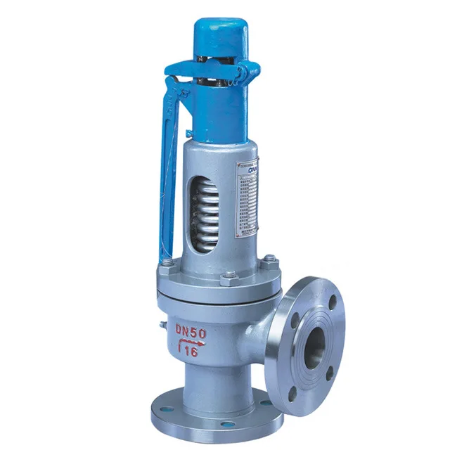
A fire-tube boiler can be fitted with one or more safety valves on the top of its shell, with each set to open when the boiler reaches its design pressure. Noisolation valvesor restrictions should be integrated between the safety valve(s) and boiler. If the valves are not installed directly onto the boiler shell, the pipework connecting the valves to the boiler must be kept clear of blockagesand water, and this must be confirmed by periodic testing.
Once a safety valve opens, steam is discharged via the exhaust pipe. Exhaust pipes must be designed to encounter as few bends as possible, be as short as possible, to have no reduction in pipe section (no internal pipe diameter reduction), and should lead to asafe point of discharge(typically outside the boiler house).
Water must be drained from the safety valve or exhaust pipework via a drainpipe. Drainpipes may be connected to holes drilled into the lowest section of the exhaust pipework, or, directly to drain holes in the safety valve body; these drains are not to be confused with the blowdown ring locking bolt, if one is fitted.
Where two safety valves are fitted, it is common that one is set just belowthe boiler’s design pressure. It is vital that each safety valve permits the full flow of steam produced when the boiler is operating at maximum capacity i.e. when the boiler is producing the maximum amount of steam it can possibly produce. If safety valves are sized correctly, a boiler can be firing at full capacity without the steam pressure exceeding design limits (because the safety valve(s) relieves pressure at a faster rate than it is accumulated).
There are various types of safety valve, including high lift and improved high lift valves, which use the force of escaping steam to open a winged valve plug to achieve greater steam flow rates. In addition to this, some valves integrate a pistonat the bottom of the spring chamber. The piston has a larger surface area than the valve plug, which leads to the valve opening with a definitive ‘pop’ sound.
Some boiler safety valves include a blowdown ring. The blowdown ring can raise or lower the valve seat ring and is used to control the amount of blowdown through the valve. This ring is locked by a bolt that protrudes through the valve and into the adjusting ring segments.
Boiler safety valves should be fitted with an easing gear (looks like a handle), used, when necessary, to rapidly release boiler pressure. Easing gears can also be used for testing a safety valve, ensuring the spindle has freedom of movement and that the valve operating mechanism functions as intended. Easing gear testing is often not conducted due to operators having difficulty with the valves resealing, but this is generally only the case with valves that are not tested often enough. Actuating the easing gear several times is often all it takes to dislodge debris from the sealing area and allow the valve to seal again. For safe operation, the easing gear handle is usually connected via steel cables to an area neighbouring the boiler.
Like pressure gauges, all safety valves should be stripped, inspected, and calibrated, at least once a year; maintenance usually occurs during statutory inspections. Calibration of each valve should be conducted by a competent person, and any valve adjustment (including the blowdown ring) should be approved and sealed by the authorised inspector. After testing and calibration, all valves should be correctly marked, suitable certificates issued, and accurate records maintained.
An accumulation test can be conducted to ensure a safety valve can relieve over-pressure steam when the boiler burner is operating at maximum capacity. Accumulation testing of safety valves must be repeated after any alterations are made to the boiler e.g. replacement of a safety valve, fuel change, or changes to the control system. If, during an accumulation test, boiler pressure rises by more than 10% of its design pressure, the test must be aborted. Before the boiler is re-tested, amendments must be made to either the safety valve relieving capacity, thesafety valve exhaust pipework, or the boiler’s steaming capacity, to ensure the 10% limit is never exceeded.
Reliefand safetyvalves prevent equipment damage by relieving over-pressurisation of fluid systems. The main difference between a relief valve and a safety valve is the extent of opening at the set-point pressure.
A relief valve gradually opens as the inlet pressure increases above the set-point. A relief valve opens only as necessary to relieve the over-pressure condition. Relief valves are typically used for liquid systems.
A safety valve rapidly‘pops’ fully openas soon as the pressure setting is reached and will stay fully open until the pressure drops below the reset pressure. The reset pressure is lower than the actuating set-point pressure. The difference between the actuating pressure set-point, and the pressure at which the safety valve resets, is called blowdown. Safety valves are typically used for gas or vapour systems.
A safety relief valve may open fully, or proportionally, once the pressure setting is reached. SRVs may be used for any fluid system (gas, liquid, or vapour).

When I teach my steam classes, I ask the attendees, "Do you test the pop safety valve?" Most do not. When I ask why, they tell me the same reason; the safety valve will leak. I joke during the classes that you do not want to test the pop safety valve on a Friday afternoon because it will almost certainly leak. I then ask, Do you check the low water cutoff? They look at me like I have a third eye and say they always check the low water cutoff. If you test the low water cutoff, you should test the pop safety valve. It is the last line of defense against a potential catastrophe. One of the things I do when performing a boiler service call is to explain the duty of the pop safety valve and ask the customer if they would like to have it tested. I explain that it could leak and if they refuse to test it, I will notate it on my service call in case something happens. In this way, my company is protected.
The best way to understand the pop safety valve is to read the instructions which came with the valve. I don"t have a life, and while you are watching the Masked Singer, I read O & M manuals. I know, I"m weird. I figure it"s my job to share things I find while reading these page-turners. The manufacturer hides all sorts of useful tidbits on the installation and maintenance of their valve. I have enclosed some information I gleaned while reading the instructions for a Conbraco/Apollo pop safety valve.
The valve must be mounted in a vertical, upright position directly to a clean, tapped opening in the top of the boiler. I see many safety valves installed horizontally and wonder if that voids the warranty. There should be no restrictions or valves in the piping to or from the safety valve. The installation instructions require the discharge piping to be schedule 40 pipe. They specifically say not to use schedule 80 pipe, which is 50% thicker than schedule 40 pipe. Many installers use copper tubing for the discharge, which does not meet the instructions. The other thing which confuses me the manufacturer instructs you not to use a pipe wrench to install the safety valve. I would wager 99% of all valves are installed using a pipe wrench. I wonder what kind of valve they want you to use.
I consult the pop safety manufacturer or the building insurance company to determine the frequency of tests. Apollo recommends quarterly testing using the Try Lever Test unless the valve is located in a severe service condition, and then it should be done more often. They further state the pop safety valve should have a Pressure Test annually before the heating season or at the end of any non-service period. This test will check your courage as you have to jump out the pressure controls and watch the operation of the boiler as the pressure builds. If the pop safety valve opens at the set pressure, the valve is working properly. This is not a test a novice should do alone.
Apollo suggests checking the pop safety valve at or near the maximum operating pressure by holding the test lever fully open for at least 5 seconds and letting it pop closed. On a low-pressure steam system, the pop safety valve is set for 15 psi. I like to run the boiler steam pressure up to 12 psi or higher to check the pop safety valve. After the test, I drop it to the operating pressure the owner requires. If the valve does not open, the boiler should be shut down until it is checked by a licensed contractor or qualified service person.
The pop safety manufacturer requires a minimum pressure differential of five psi between the pressure relief valve set pressure and the boiler operating pressure. It further states, Under no circumstances should the margin be less than five psig. On a low-pressure steam boiler, the pop safety valve will be set for 15 psi. That means the boiler steam pressure should be ten psi or lower. In breweries, it is common to see the boiler pressure set at 12-14 psi. This is less than the five psi differential and could create a dangerous condition.
A: Maintenance should be performed on a regular basis. An initial inspection interval of no longer than 12 months is recommended. The user must establish an appropriate inspection interval depending on the service conditions, the condition of the valve and the level of performance desired.
The ASME Boiler and Pressure Vessel Code does not require nor address testing installed valves. The only thing the code states are design and installation requirements, such as some valves must have a lifting lever. For instance for Section VIII:
“Each pressure relief valve on air, water over 140° F, or steam service shall have a substantial lifting device which when activated will release the seating force on the disk when the pressure relief valve is subjected to a pressure of at least 75% of the set pressure of the valve.”
A: This drain hole is required on some models by the ASME Boiler and Pressure Vessel Code. It is intended to prevent any condensate from accumulating in the body that may freeze or corrode internal valve parts and prevent the valve from opening. The drain hole should be piped away to safely dispose of any discharge or condensate.
A: This is often a confusing topic. The correct installation often looks backwards from what appears to be correct. A paper instruction tag illustrating the proper connection is attached to each valve. Vacuum valves should have the NPT threads that are cast integral to the body attached to the vacuum source. See the assembly drawing for additional clarification.
A: Typically, the valve should be nameplate set to open at the MAWP (Maximum Allowable Working Pressure) of the vessel the valve is intended to protect. There is a tolerance to actual set pressure, which means a valve set at 100 psig nameplate may open slightly above or below 100 psig. Consult the current ASME Boiler and Pressure Vessel Code for tolerance classes and special situations when the set pressure may be different than the MAWP.
A: It is normal for spring-operated safety valves to exhibit leakage or simmer/warn, as the system operating pressure approaches the nameplate set pressure, typically in the 80%-90% range of nameplate set pressure. The ASME Boiler and Pressure Vessel Code does not require a specific seat tightness requirement. A certain level of leakage is allowed per manufacturers’ literature and API-527 Seat Tightness Performance Standards, both of which can be found in the Technical Reference Catalog and in the Data Supplement, summarized as follows:
API-527 Standard Seat Tightness Performance: A Functional Test Report (FTR) is automatically provided for valves ordered to API-527. See API 527 for complete details.
At very low set pressures, the ratio of the downward spring force as compared to the upward pressure force is very small. In these cases it may be impossible to achieve seat tightness.
A: Maintain a minimum operating gap of 10% between the system operating pressure and the safety valve’s nameplate set pressure. Since direct spring-operated safety valves may “simmer” or “warn” at 90% of the nameplate set pressure, and since the factory standard leak test is performed at 80% of nameplate set pressure, better seat tightness performance can be expected with an operating gap of 20%.
A: It may not be. Warn/simmer or seat leakage is sometimes mistaken for set pressure. Visible or audible leakage or system pressure drop is not set pressure. The correct definition of set pressure is:
Variance of set pressure is allowed, i.e., a Section VIII air valve with a nameplate of 100 psig set pressure may open from 97 psig to 103 psig, but will be factory set around 102 psig.
Gage issues may lead to incorrect reporting of set pressure. Ensure the gage is within calibration and is accurate for the pressure being measured. Rapid increases in system pressure (more than 2 psig/second, water hammer, reciprocating pumps) can make the valve appear to be opening early because the gage cannot accurately report the pressure to which the valve is exposed.
A: Yes. Section I valves have more stringent setting blowdown requirements and may be used in Section VIII steam applications since they meet all the requirements as specified in Section VIII UG-125(a) “Pressure Relief Devices,” which states pressure relief devices must be “in accordance with the requirements of UG-125 through UG-137.” In addition, UG-125(b) actually specifies that even unfired steam boilers MUST use a Section I pressure relief device.
A: Section VIII UG-136(a)(3) states, “Each pressure relief valve on air, water over 140° F (60° C), or steam service shall have a substantial lifting device which when activated will release the seating force on the disk when the pressure relief valve is subjected to a pressure of at least 75% of the set pressure of the valve.”
The user has a documented procedure and an associated implementation program for the periodic removal of the pressure relief valves for inspection and testing, and repair as necessary.
A: Back pressure reduces set pressure on a one-to-one basis, i.e., a valve set at 100 psig subjected to a backpressure at the outlet of 10 psig will not actuate until system pressure reaches 110 psig. Back pressure drastically reduces capacity; typically backpressure of 10% of set pressure will decrease capacity by 50%. Specific capacity reduction should be determined by the user on a case-by-case basis by flow testing. Back pressure in excess of 10% of set pressure is not recommended.
A: The ASME Boiler and Pressure Vessel Code does not have blowdown requirements for Section VIII (or non-code) valves. Blowdown may vary from less than 2% to more than 50%, depending on many factors including: valve design, dimensional tolerance variation, where the set pressure falls in the set pressure range of a spring, spring rate/force ratio, warn ring/guide settings, etc. Typical blowdown for most valves is 15% to 30%, but cannot be guaranteed. VM
Jim Knox is president, Allied Valve, Inc. (www.alliedvalve.com), a valve repair service company and supplier of Tyco Kunkle and Dresser Consolidated safety valves in the Midwest. Reach him at knoxj@alliedvalveinc.com.
ValvTechnologies and Severn Glocon have reached a partnership agreement that will see collaboration between two of the world’s leading engineering and manufacturing companies specializing in innovative, high-end, severe-service valves.
This article outlines the challenges of lifting large valve assemblies weighing several tons and illustrates the industrial rigging equipment and lifting operations typically used for these valves.

Because a safety valve is often the last device to prevent catastrophic failure under pressure conditions, it is important that the valve works at all times i.e. it must be 100% reliable.
Safety valves should be installed wherever the maximum allowable working pressure of a system or pressure containing vessel is likely to be exceeded, in particular under fault conditions due to the failure of another piece of equipment in the system.
The term “Safety Valve” and “Relief Valve” are generic terms to describe a variety of pressure relief devices. A wide range is available based on the application and required performance criteria. The different designs are required to meet numerous national standards.
The images below show the devastating results of a failed Safety valve (due to poor maintenace) or ones which have been incorrectly sized, installed or maintained.
A spring-loaded pressure relief valve which is designed to open to relieve excess pressure and to reclose and prevent the further flow of fluid after normal conditions have been restored. It is characterised by a rapid-opening "pop" action or by opening in a manner generally proportional to the increase in pressure over the opening pressure. It may be used for either compressible or incompressible fluids, depending on design, adjustment, or application.
Relief valve - A pressure relief device actuated by inlet static pressure having a gradual lift generally proportional to the increase in pressure over opening pressure.
Safety relief valve - A pressure relief valve characterised by rapid opening or pop action, or by opening in proportion to the increase in pressure over the opening pressure, depending on the application, and which may be used either for liquid or compressible fluid.
Safety valve - A valve which automatically, without the assistance of any energy other than that of the fluid concerned, discharges a quantity of the fluid so as to prevent a predetermined safe pressure being exceeded, and which is designed to re-close and prevent further flow of fluid after normal pressure conditions of service have been restored.
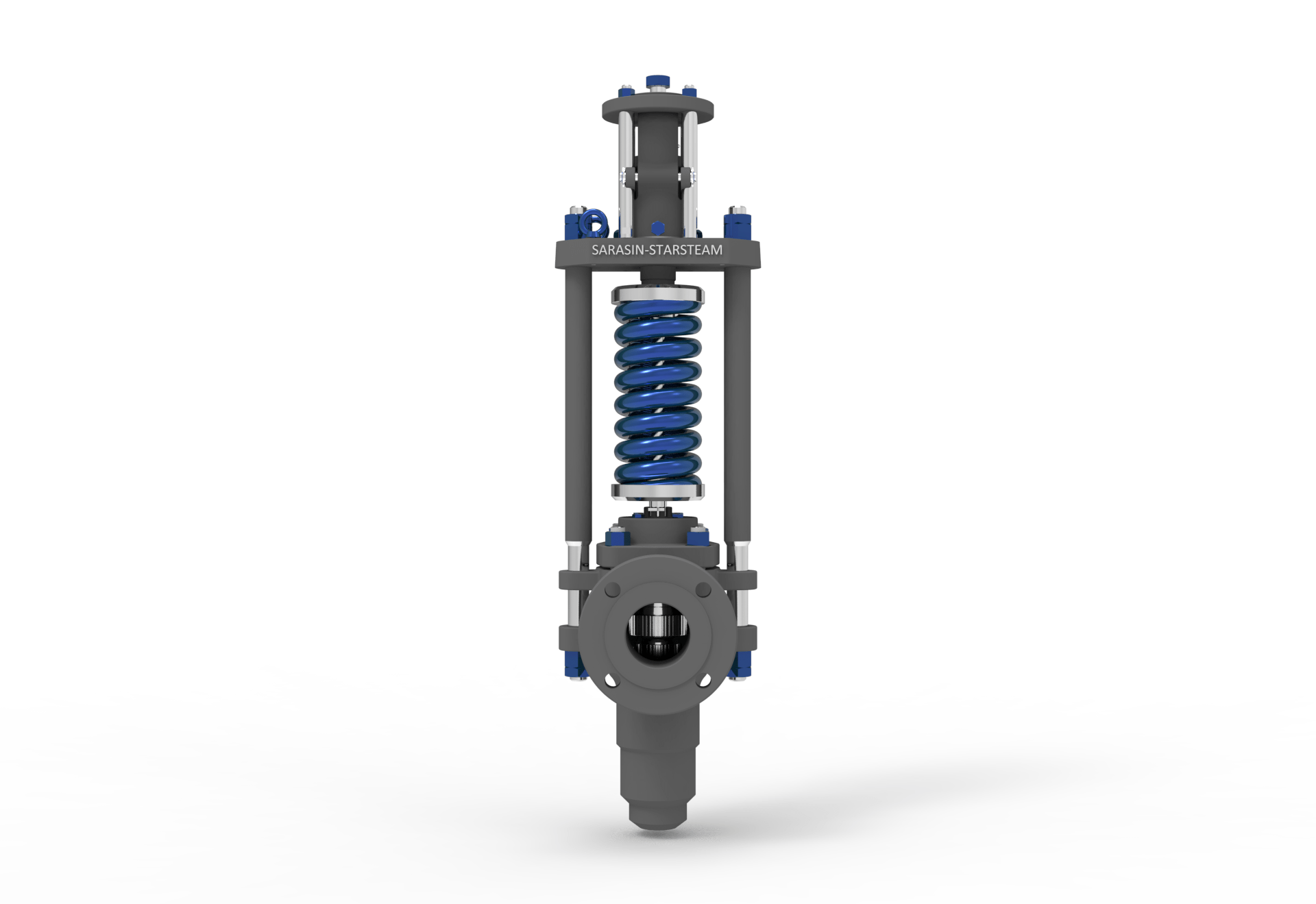
The images below show a standard Relief valve and a standard Safety valve from a well-known UK manufacturer. Each manufacturer does things slightly differently however all of the basic components and principles of operation are the same. As described previously, a safety valve differs from a relief valve in that it opens rapidly once the set pressure has been reached. For the same inlet size and with the valve in the closed position, the surface area that the pressure on the inlet side will see is the same. When the set pressure is reached and the valve starts to open, the disk on a Safety valve is larger (see the diagrams below) and hence the same pressure then sees a much larger surface area and consequently the force increases greatly causing the valve to open quickly and hence the characteristic pop action.
The image below shows the above Safety valves and Relief valves dismantled. The disk diameter on the 1" (DN25) Safety valve is only 7mm larger than on the Relief valve which doesnt sound like much, but when you calculate the areas it is an increase of 36%.
This diagram represents a Safety valve in its very simplest form. The force acting on the inlet side of the disk is acting against the force applied by the spring plus the force applied by the back pressure on the top of the disk.
The valve remains closed when(PI x Ab) < Fs + (PB x At), is in equilibrium when(PI x Ab) = Fs + (PB x At) and opens when(PI x Ab) > Fs + (PB x At) were PI = Inlet pressure, PB = Back pressure, At = Top of disk area, Ab = Bottom of disk area. Things to notice from this design are that if PB is variable and quite large relative to PI, then this will cause the pressure at which the valve opens to vary which is undesirable. The following two designs (Fig 3 & Fig 4) are available that eliminate the effect of back pressure on the set pressure.
The bellows prevents backpressure acting on the top side of the disk. In relation to the piston there is no top side within the main body of the valve hence again the back pressure cannot affect the set pressure. Bellows failure is an important concern in critical applications where a very precise set pressure is required. In these cases some mechanism to detect a leak of process medium out of the top vent would be implemented. Piston designs are not usually found in conventional Safety valves but are more common in Pilot Operated Safety valves.
API 520 Practice Guidelines: a conventional design should not typically be used when the built-up backpressure is greater than 10% of the set pressure at 10% over pressure. European standard EN ISO 4126: the built-up backpressure should be limited to 10% of the set pressure when the valve is discharging at the certified capacity.
In a conventional design (no bellows), the superimposed backpressure will affect the opening characteristic and set value, but the combined backpressure will alter the closing (blowdown) and re-seat value.
Overpressure is the percentage over the set pressure by which the valve is fully open. The blowdown is the percentage below the set pressure by which the valve is fully closed.
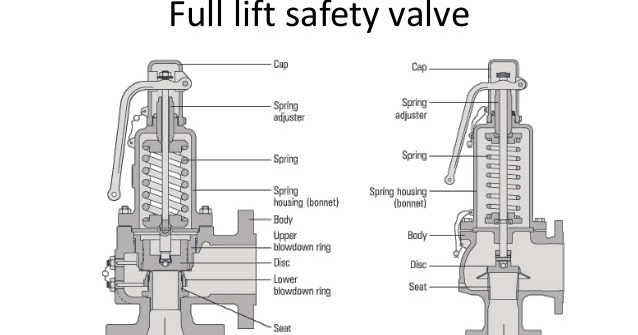
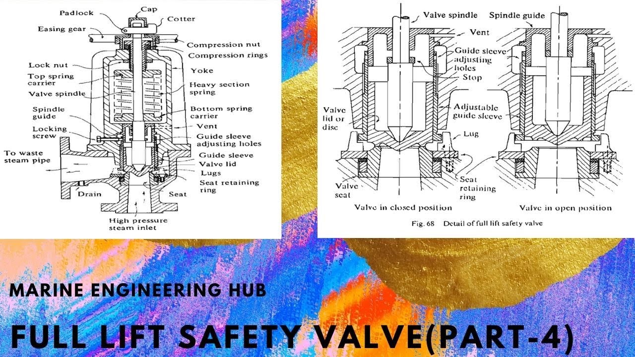
The basic elements of the design are right angle pattern valve body, inlet can be either a full nozzle or a semi-nozzle type. With a full nozzle design has the “wetted” inlet tract formed from one piece (as per figure 6) with the seat integrated into the top of the nozzle. The internal bore of the nozzle and the disc is the only part of the valve that is exposed to the process fluid with the valve in the closed position. A semi-nozzle design consists of a seating ring fitted into the body.The disc is held onto the seat by the stem, with the downward force coming from the compression on the spring mounted in the bonnet. The amount of compression on the spring is adjusted by the spring adjuster under the cap.
Unless bellows or diaphragm sealing is used, process fluid will enter the spring housing (or bonnet). The amount of fluid depends on the particular design of safety valve. If emission of this fluid into the atmosphere is acceptable, the spring housing may be vented to the atmosphere - an open bonnet. This is usually advantageous when the safety valve is used on high temperature fluids or for boiler applications as, otherwise, high temperatures can relax the spring, altering the set pressure of the valve. However, using an open bonnet exposes the valve spring and internals to environmental conditions, which can lead to damage and corrosion of the spring.
When the fluid must be completely contained by the safety valve (and the discharge system), it is necessary to use a closed bonnet, which is not vented to the atmosphere. This type of spring enclosure is almost universally used for small screwed valves and, it is becoming increasingly common on many valve ranges since, particularly on steam, discharge of the fluid could be hazardous to personnel.
A lifting mechanism is recommended to test for correct valve operation at all times where corrosion, caking, or any deposit could prevent the opening operation.
Foreign particles can lodge under the seat of the valve when it discharges. The lifting lever allows you to lift the valve and flush the obstruction. Pressure relief valves for Section VIII require a lift lever on all air, steam, and hot water valves used at temperatures over 60 degC. Typically used where periodic testing of the valve in location is desired to assure its operation. With an Open lifting lever design, when the valve discharges, fluid media will escape into the atmosphere around the open lifting lever assembly. If this is not desirable or when back pressure is present you would select a Packed Lifting Lever design.
As described above, this type is selected where leakage of the media to the atmosphere during valve discharge or during back pressure would be un-desirable. A packed lever design is a completely sealed assembly.
Some people consider a bolted and gasketed design better to the standard screw cap for applications with back pressure and / or vibration hence some manufacturers offer this as an option.
Under certain circumstances i.e. under the start-up conditions of a plant or to pressure test the system in a controlled environment, it may be required that the valve is prevented from opening.This is achieved by screwing the bolt (shown on the wire) into the cap which screws down onto the stem and prevents it lifting. Obviously it is important that test gags are removed prior to placing the valve into service.
The bellows is designed to cover the same area on the back of the disc equal to the seat area hence the back pressure will have no effect on the set pressure. See the previous section “Basic Safety Valve Principles”. Bellows also protects the spindle, spindle guide and spring from the process medium.
A disc is held against the nozzle by a spring, which is contained in a cast bonnet. The spring is adjusted by a compression screw to permit the calibration of opening or set pressure. An adjustable nozzle ring, threaded onto the nozzle, controls the geometry of the fluid exit control chamber (also known as a huddling chamber). The control chamber (huddling chamber) geometry is very important in controlling valve opening and closing pressures and stability of operation. The nozzle ring is locked into position by a ring pin assembly as shown in Figure 15 below.
Under normal system operation the valve remains in the closed position because the spring force (Fs) is greater than the system pressure acting on the internal nozzle seating area (PA). If system pressure increases to a point when these forces are equal, then the set pressure is reached. The disc lifts and fluid flows through the valve. When pressure in the system returns to a safe level, the valve closes.
Just prior to reaching set point, the pressure relief valve leaks system fluid into the huddling chamber. The fluid now acts on a larger area of the disc inside the huddling chamber (PAh), causing the valve to experience an instantaneous increase in the opening force. Refer to the figure 16 above to see relationship between Nozzle Area (A) and the Huddling Chamber Area (Ah). System pressure acting on the larger area will suddenly open the safety relief valve at a rapid rate.
Although the opening is rapid and dramatic, the valve does not open fully at set point. The system pressure must increase above set point to open the valve to its full lift and capacity position. Maximum lift and certified flow rates will be achieved within the allowable limits (overpressure) established by various codes and standards. All pressure relief ales are allowed an overpressure allowance to reach full rated flow. The allowable over pressure can vary from 10% to 21% on unfired vessels and systems, depending on the sizing basis, number of valves, and whether a fire condition is encountered.
Once the valve has controlled the pressure excursion, system pressure will start to reduce. Since the huddling chamber area is now controlling the exit fluid flow, system pressure must reduce below the set point before the spring force is able to close the valve. The difference between the set pressure and the closing pressure is called blowdown, and is usually expressed as a percentage of set pressure. The typical blowdown can vary from 7% to 10%, the industry standard.
The nozzle ring adjustment changes the shape and volume of the huddling chamber, and its position will affect both the opening and the closing characteristics of the valve. When the nozzle ring is adjusted to its top position, the huddling chamber is restricted to its maximum. The valve will usually pop very distinctly with a minimum simmer (leakage before opening), but the blowdown will increase. When the nozzle ring is lowered to its lowest position, minimal restriction to the huddling chamber occurs. At this position, simmer increases and the blowdown decreases. The final ring position is somewhere between these two extremes to provide optimal performance.
On liquid service, a different dynamic situation exists. Liquids do not expand when flowing across orifices, and a small amount of fluid flow across the nozzle will produces a large local pressure drop at the nozzle orifice. This local pressure drop causes the spring to reclose the valve if the fluid flow is minimal. Liquids leaking into the huddling chamber can quickly drain out by gravity and prevent fluid pressure from building up in the secondary area of the huddling chamber. Liquid relief valves are thus susceptible to a phenomenon called chatter, especially at low fluid flow rates. Chatter is the rapid opening and closing of the pressure relief valve and is always destructive.
Because of the difference in the characteristics of gases and liquids, some valve designs require a special liquid trim in order to meet ASME Code Section VIII performance criteria of full rated liquid flow at 10% overpressure. With liquids since no visible or audible pop is heard at set point, the set pressure is defined as the pressure when the first heavy flow occurs (a pencil sized steady stream of water that remains unbroken for approximately one inch).
Manufacturers usually state their recommended testing procedure and testing intervals in their Installation, Operating and Maintenance Instructions (IOM). Typically, they recommend a manual test every 3 or 6 months (assuming it has a lifting lever) and a set pressure test every 12 months. It is sensible to incorporate these into your maintenance plan so they are not missed. Sometimes your insurance company may require them to be tested even more regularly than this i.e. every 6 months. Testing in most cases involves removing them from your system and having them recertified in an approved workshop.
If you have a system that is shut down for annual maintenance then this is an ideal time to remove your Safety valves and have them inspected and recertified.
For systems that can only be off for short periods of time, it is sensible to keep a spare valve to swap over and then the removed valve can be inspected and recertified.
For systems that cannot be shut down, you will need to use a changeover valve which allows you to swap between Safety valves allowing one to be removed for inspection and testing.
For larger Safety valves on systems that run continuously, you may consider using in-situ testing. This method does have some limitations however since you cannot visually inspect the inside of the valve, but it will tell you if the valve is opening at the correct set pressure.
(a) A valve passing (leaking) on the outlet side when the valve is supposed to be closed. This can happen to valves of any age (new or old) and occurs if debris contained in the medium passes through the valve at a point when the valve lifts, and the debris either traps or damages the internals of the valve. On soft seated valves, hard particles may embed themselves in the soft material causing re-sealing issues. If your valve has a lifting lever and it is safe to do so, then it is worth lifting the handle for a few seconds which will hopefully clear any debris allowing the valve to reseal correctly. If this isn’t an option or it doesn’t cure the problem, then the valve will need to be removed and returned for maintenance and recertification. The time we often see this the most is during the startup of a system and there is a pressure spike, hence this is why it is extremely important that a system is flushed out well before hand.
%20Cross-Section.png)
Safety valves are an arrangement or mechanism to release a substance from the concerned system in the event of pressure or temperature exceeding a particular preset limit. The systems in the context may be boilers, steam boilers, pressure vessels or other related systems. As per the mechanical arrangement, this one get fitted into the bigger picture (part of the bigger arrangement) called as PSV or PRV that is pressure safety or pressure relief valves.
This type of safety mechanism was largely implemented to counter the problem of accidental explosion of steam boilers. Initiated in the working of a steam digester, there were many methodologies that were then accommodated during the phase of the industrial revolution. And since then this safety mechanism has come a long way and now accommodates various other aspects.
These aspects like applications, performance criteria, ranges, nation based standards (countries like United States, European Union, Japan, South Korea provide different standards) etc. manage to differentiate or categorize this safety valve segment. So, there can be many different ways in which these safety valves get differentiated but a common range of bifurcation is as follows:
The American Society of Mechanical Engineers (ASME) I tap is a type of safety valve which opens with respect to 3% and 4% of pressure (ASME code for pressure vessel applications) while ASME VIII valve opens at 10% over pressure and closes at 7%. Lift safety valves get further classified as low-lift and full lift. The flow control valves regulate the pressure or flow of a fluid whereas a balanced valve is used to minimize the effects induced by pressure on operating characteristics of the valve in context.
A power operated valve is a type of pressure relief valve is which an external power source is also used to relieve the pressure. A proportional-relief valve gets opened in a relatively stable manner as compared to increasing pressure. There are 2 types of direct-loaded safety valves, first being diaphragms and second: bellows. diaphragms are valves which spring for the protection of effects of the liquid membrane while bellows provide an arrangement where the parts of rotating elements and sources get protected from the effects of the liquid via bellows.
In a master valve, the operation and even the initiation is controlled by the fluid which gets discharged via a pilot valve. Now coming to the bigger picture, the pressure safety valves based segment gets classified as follows:
So all in all, pressure safety valves, pressure relief valves, relief valves, pilot-operated relief valves, low pressure safety valves, vacuum pressure safety valves etc. complete the range of safety measures in boilers and related devices.
Safety valves have different discharge capacities. These capacities are based on the geometrical area of the body seat upstream and downstream of the valve. Flow diameter is the minimum geometrical diameter upstream and downstream of the body seat.
The nominal size designation refers to the inlet orifice diameter. A safety Valve"s theoretical flowing capacity is the mass flow through an orifice with the same cross-sectional area as the valve"s flow area. This capacity does not account for the flow losses caused by the valve. The actual capacity is measured, and the certified flow capacity is the actual flow capacity reduced by 10%.
A safety valve"s discharge capacity is dependent on the set pressure and position in a system. Once the set pressure is calculated, the discharge capacity must be determined. Safety valves may be oversized or undersized depending on the flow throughput and/or the valve"s set pressure.
The actual discharge capacity of a safety valve depends on the type of discharge system used. In liquid service, safety valves are generally automatic and direct-pressure actuated.
A safety valve is used to protect against overpressure in a fluid system. Its design allows for a lift in the disc, indicating that the valve is about to open. When the inlet pressure rises above the set pressure, the guide moves to the open position, and media flows to the outlet via the pilot tube. Once the inlet pressure falls below the set pressure, the main valve closes and prevents overpressure. There are five criteria for selecting a safety valve.
The first and most basic requirement of a safety valve is its ability to safely control the flow of gas. Hence, the valve must be able to control the flow of gas and water. The valve should be able to withstand the high pressures of the system. This is because the gas or steam coming from the boiler will be condensed and fill the pipe. The steam will then wet the safety valve seat.
The other major requirement for safety valves is their ability to prevent pressure buildup. They prevent overpressure conditions by allowing liquid or gas to escape. Safety valves are used in many different applications. Gas and steam lines, for example, can prevent catastrophic damage to the plant. They are also known as safety relief valves. During an emergency, a safety valve will open automatically and discharge gas or liquid pressure from a pressurized system, preventing it from reaching dangerous levels.
The discharge capacity of a safety valve is based on its orifice area, set pressure, and position in the system. A safety valve"s discharge capacity should be calculated based on the maximum flow through its inlet and outlet orifice areas. Its nominal size is often determined by manufacturer specifications.
Its discharge capacity is the maximum flow through the valve that it can relieve, based on the maximum flow through each individual flow path or combined flow path. The discharge pressure of the safety valve should be more than the operating pressure of the system. As a thumb rule, the relief pressure should be 10% above the working pressure of the system.
It is important to choose the discharge capacity of a safety valve based on the inlet and output piping sizes. Ideally, the discharge capacity should be equal to or greater than the maximum output of the system. A safety valve should also be installed vertically and into a clean fitting. While installing a valve, it is important to use a proper wrench for installation. The discharge piping should slope downward to drain any condensate.
The discharge capacity of a safety valve is measured in a few different ways. The first is the test pressure. This gauge pressure is the pressure at which the valve opens, while the second is the pressure at which it re-closes. Both are measured in a test stand under controlled conditions. A safety valve with a test pressure of 10,000 psi is rated at 10,000 psi (as per ASME PTC25.3).
The discharge capacity of a safety valve should be large enough to dissipate a large volume of pressure. A small valve may be adequate for a smaller system, but a larger one could cause an explosion. In a large-scale manufacturing plant, safety valves are critical for the safety of personnel and equipment. Choosing the right valve size for a particular system is essential to its efficiency.
Before you use a safety valve, you need to know its discharge capacity. Here are some steps you need to follow to calculate the discharge capacity of a safety valve.
To check the discharge capacity of a safety valve, the safety valve should be installed in the appropriate location. Its inlet and outlet pipework should be thoroughly cleaned before installation. It is important to avoid excessive use of PTFE tape and to ensure that the installation is solid. The safety valve should not be exposed to vibration or undue stress. When mounting a safety valve, it should be installed vertically and with the test lever at the top. The inlet connection of the safety valve should be attached to the vessel or pipeline with the shortest length of pipe. It must not be interrupted by any isolation valve. The pressure loss at the inlet of a safety valve should not exceed 3% of the set pressure.
The sizing of a safety valve depends on the amount of fluid it is required to control. The rated discharge capacity is a function of the safety valve"s orifice area, set pressure, and position in the system. Using the manufacturer"s specifications for orifice area and nominal size of the valve, the capacity of a safety valve can be determined. The discharge flow can be calculated using the maximum flow through the valve or the combined flows of several paths. When sizing a safety valve, it"s necessary to consider both its theoretical and actual discharge capacity. Ideally, the discharge capacity will be equal to the minimum area.
To determine the correct set pressure for a safety valve, consider the following criteria. It must be less than the MAAP of the system. Set pressure of 5% greater than the MAAP will result in an overpressure of 10%. If the set pressure is higher than the MAAP, the safety valve will not close. The MAAP must never exceed the set pressure. A set pressure that is too high will result in a poor shutoff after discharge. Depending on the type of valve, a backpressure variation of 10% to 15% of the set pressure cannot be handled by a conventional valve.

Pressure relief valves prevent a boiler from becoming dangerously over-pressurized. If something goes wrong in a boiler and the pressure spikes, or gradually moves beyond spec, the pressure relief valve will open to vent excess steam or water to protect the other components of the boiler from damage.
Pressure relief valves are designed to open when they are exposed to a pressure level beyond the boiler’s specified safe limits. Different boiler designs require different operating pressures and temperatures, and pressure relief valves can be found in multiple locations in a boiler. That’s why WARE stocks pressure relief valves for a wide range of applications and specifications.
Pressure relief valves are a safeguard against over-pressurization. If a boiler’s internal pressure goes beyond spec, it can cause significant stress on the other parts of the system. If left unchecked, rising pressure can also cause dangerous explosions.
If the valve is a fail-open design, it will immediately start to release steam or water, preventing the boiler from reaching proper operating conditions.
It’s important to know which kind of valve is in the boiler system you’re operating, so you can know the signs of a potentially failing pressure relief valve.
Things to Consider about relief valves:When a pressure relief valve is activated, also known as “popping off”, it will vent steam or hot water. Make sure every pressure relief valve drains to a safe area.Check your pressure relief valves regularly for leaks. If you can see or hear steam or water escaping when the boiler is not over pressure, contact a professional for an inspection right away.Keep your pressure relief valves clean. If dirt, grime, soot, or precipitate build up on the valve, it may not be able to operate properly.
Explore over 750+ explanatory videos on boilers and boiler systems on our Youtube channel. Our videos can help you quickly grasp complex boiler topics. Watch more here!
There are a few common causes of pressure relief valve failure. The valve ca


 8613371530291