
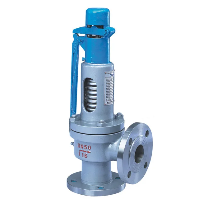
boiler safety valve lifting pressure free sample
Boiler explosions have been responsible for widespread damage to companies throughout the years, and that’s why today’s boilers are equipped with safety valves and/or relief valves. Boiler safety valves are designed to prevent excess pressure, which is usually responsible for those devastating explosions. That said, to ensure that boiler safety valves are working properly and providing adequate protection, they must meet regulatory specifications and require ongoing maintenance and periodic testing. Without these precautions, malfunctioning safety valves may fail, resulting in potentially disastrous consequences.
Boiler safety valves are activated by upstream pressure. If the pressure exceeds a defined threshold, the valve activates and automatically releases pressure. Typically used for gas or vapor service, boiler safety valves pop fully open once a pressure threshold is reached and remain open until the boiler pressure reaches a pre-defined, safe lower pressure.
Boiler relief valves serve the same purpose – automatically lowering boiler pressure – but they function a bit differently than safety valves. A relief valve doesn’t open fully when pressure exceeds a defined threshold; instead, it opens gradually when the pressure threshold is exceeded and closes gradually until the lower, safe threshold is reached. Boiler relief valves are typically used for liquid service.
There are also devices known as “safety relief valves” which have the characteristics of both types discussed above. Safety relief valves can be used for either liquid or gas or vapor service.
Nameplates must be fastened securely and permanently to the safety valve and remain readable throughout the lifespan of the valve, so durability is key.
The National Board of Boiler and Pressure Vessel Inspectors offers guidance and recommendations on boiler and pressure vessel safety rules and regulations. However, most individual states set forth their own rules and regulations, and while they may be similar across states, it’s important to ensure that your boiler safety valves meet all state and local regulatory requirements.
The National Board published NB-131, Recommended Boiler and Pressure Vessel Safety Legislation, and NB-132, Recommended Administrative Boiler and Pressure Vessel Safety Rules and Regulationsin order to provide guidance and encourage the development of crucial safety laws in jurisdictions that currently have no laws in place for the “proper construction, installation, inspection, operation, maintenance, alterations, and repairs” necessary to protect workers and the public from dangerous boiler and pressure vessel explosions that may occur without these safeguards in place.
The American Society of Mechanical Engineers (ASME) governs the code that establishes guidelines and requirements for safety valves. Note that it’s up to plant personnel to familiarize themselves with the requirements and understand which parts of the code apply to specific parts of the plant’s steam systems.
High steam capacity requirements, physical or economic constraints may make the use of a single safety valve impossible. In these cases, using multiple safety valves on the same system is considered an acceptable practice, provided that proper sizing and installation requirements are met – including an appropriately sized vent pipe that accounts for the total steam venting capacity of all valves when open at the same time.
The lowest rating (MAWP or maximum allowable working pressure) should always be used among all safety devices within a system, including boilers, pressure vessels, and equipment piping systems, to determine the safety valve set pressure.
Avoid isolating safety valves from the system, such as by installing intervening shut-off valves located between the steam component or system and the inlet.
Contact the valve supplier immediately for any safety valve with a broken wire seal, as this indicates that the valve is unsafe for use. Safety valves are sealed and certified in order to prevent tampering that can prevent proper function.
Avoid attaching vent discharge piping directly to a safety valve, which may place unnecessary weight and additional stress on the valve, altering the set pressure.

In order to ensure that the maximum allowable accumulation pressure of any system or apparatus protected by a safety valve is never exceeded, careful consideration of the safety valve’s position in the system has to be made. As there is such a wide range of applications, there is no absolute rule as to where the valve should be positioned and therefore, every application needs to be treated separately.
A common steam application for a safety valve is to protect process equipment supplied from a pressure reducing station. Two possible arrangements are shown in Figure 9.3.3.
The safety valve can be fitted within the pressure reducing station itself, that is, before the downstream stop valve, as in Figure 9.3.3 (a), or further downstream, nearer the apparatus as in Figure 9.3.3 (b). Fitting the safety valve before the downstream stop valve has the following advantages:
• The safety valve can be tested in-line by shutting down the downstream stop valve without the chance of downstream apparatus being over pressurised, should the safety valve fail under test.
• When setting the PRV under no-load conditions, the operation of the safety valve can be observed, as this condition is most likely to cause ‘simmer’. If this should occur, the PRV pressure can be adjusted to below the safety valve reseat pressure.
Indeed, a separate safety valve may have to be fitted on the inlet to each downstream piece of apparatus, when the PRV supplies several such pieces of apparatus.
• If supplying one piece of apparatus, which has a MAWP pressure less than the PRV supply pressure, the apparatus must be fitted with a safety valve, preferably close-coupled to its steam inlet connection.
• If a PRV is supplying more than one apparatus and the MAWP of any item is less than the PRV supply pressure, either the PRV station must be fitted with a safety valve set at the lowest possible MAWP of the connected apparatus, or each item of affected apparatus must be fitted with a safety valve.
• The safety valve must be located so that the pressure cannot accumulate in the apparatus viaanother route, for example, from a separate steam line or a bypass line.
It could be argued that every installation deserves special consideration when it comes to safety, but the following applications and situations are a little unusual and worth considering:
• Fire - Any pressure vessel should be protected from overpressure in the event of fire. Although a safety valve mounted for operational protection may also offer protection under fire conditions,such cases require special consideration, which is beyond the scope of this text.
• Exothermic applications - These must be fitted with a safety valve close-coupled to the apparatus steam inlet or the body direct. No alternative applies.
• Safety valves used as warning devices - Sometimes, safety valves are fitted to systems as warning devices. They are not required to relieve fault loads but to warn of pressures increasing above normal working pressures for operational reasons only. In these instances, safety valves are set at the warning pressure and only need to be of minimum size. If there is any danger of systems fitted with such a safety valve exceeding their maximum allowable working pressure, they must be protected by additional safety valves in the usual way.
In order to illustrate the importance of the positioning of a safety valve, consider an automatic pump trap (see Block 14) used to remove condensate from a heating vessel. The automatic pump trap (APT), incorporates a mechanical type pump, which uses the motive force of steam to pump the condensate through the return system. The position of the safety valve will depend on the MAWP of the APT and its required motive inlet pressure.
This arrangement is suitable if the pump-trap motive pressure is less than 1.6 bar g (safety valve set pressure of 2 bar g less 0.3 bar blowdown and a 0.1 bar shut-off margin). Since the MAWP of both the APT and the vessel are greater than the safety valve set pressure, a single safety valve would provide suitable protection for the system.
However, if the pump-trap motive pressure had to be greater than 1.6 bar g, the APT supply would have to be taken from the high pressure side of the PRV, and reduced to a more appropriate pressure, but still less than the 4.5 bar g MAWP of the APT. The arrangement shown in Figure 9.3.5 would be suitable in this situation.
Here, two separate PRV stations are used each with its own safety valve. If the APT internals failed and steam at 4 bar g passed through the APT and into the vessel, safety valve ‘A’ would relieve this pressure and protect the vessel. Safety valve ‘B’ would not lift as the pressure in the APT is still acceptable and below its set pressure.
It should be noted that safety valve ‘A’ is positioned on the downstream side of the temperature control valve; this is done for both safety and operational reasons:
Operation - There is less chance of safety valve ‘A’ simmering during operation in this position,as the pressure is typically lower after the control valve than before it.
Also, note that if the MAWP of the pump-trap were greater than the pressure upstream of PRV ‘A’, it would be permissible to omit safety valve ‘B’ from the system, but safety valve ‘A’ must be sized to take into account the total fault flow through PRV ‘B’ as well as through PRV ‘A’.
A pharmaceutical factory has twelve jacketed pans on the same production floor, all rated with the same MAWP. Where would the safety valve be positioned?
One solution would be to install a safety valve on the inlet to each pan (Figure 9.3.6). In this instance, each safety valve would have to be sized to pass the entire load, in case the PRV failed open whilst the other eleven pans were shut down.
If additional apparatus with a lower MAWP than the pans (for example, a shell and tube heat exchanger) were to be included in the system, it would be necessary to fit an additional safety valve. This safety valve would be set to an appropriate lower set pressure and sized to pass the fault flow through the temperature control valve (see Figure 9.3.8).

Stainless Steel Safety Relief Valve is a safety mechanism deployed in applications to prevent them from bursting under pressure. Suraj Metal Corporationis a leading manufacturer and supplier of the different types such as the Brass Safety Valveand others in various sizes and dimensions. The valves are fitted with the pipelines in a way that when the pressure goes above the threshold level, the Stainless Steel Air Safety Valveopens up and relieves the system of pressure.
This is important to prevent the pipes from being damaged or bursting under high pressure. The Stainless Steel Safety Exhaust Ball Valveis used in the exhaust systems where the temperature plays major role. When the temperature exceeds certain point, it increases pressure and the safety valve opens and balances the pressure in the system. The spring loaded boiler safety valveis used in boilers and heat exchanger systems where steam and hot water are circulated through pipes. There are different gas safety valvetypes and each of these differ in their purpose and functions. Please feel free to contact us for more information on the different types of air compressor pressure relief valveand others with pricing.
We Keep Bulk Stock of CF8 stainless steel Pressure Safety Valve at our stockyard, contact us for Free Sample & stock list, View Brass Safety Valve Dimension chart
find Stainless Steel Safety Exhaust Ball Valve Dimensions, price list, size chart here, Buy ASTM A351 CF8M 316 temperature safety valve at best price in India
(f) When operating conditions are changed, or additional boiler heating surface is installed, the valve capacity shall be increased, if necessary, to meet the new conditions and be in accordance with HG-400.l (e). The additional valves required, on account of changed conditions, may be installed on the outlet piping provided there is no intervening valve.
(a) Each hot water heating or supply boiler shall have at least one officially rated safety relief valve, of the automatic reseating type, identified with the V or HV Symbol, and set to relieve at or below the maximum allowable working pressure of the boiler.
(b) Hot water heating or supply boilers limited to a water temperature not in excess of 210°F (99°C) may have, in lieu of the valve(s) specified in (a) above, one or more officially rated temperature and pressure safety relief valves of the automatic reseating type identified with the HV symbol, and set to relieve at or below the maximum allowable working pressure of the boiler.
(c) When more than one safety relief valve is used on either hot water heating or hot water supply boilers, the additional valves shall be officially rated and may have a set pressure within a range not to exceed 6 psi (40 kPa) above the maximum allowable working pressure of the boiler up to and including 60 psi (400 kPa), and 5% for those having a maximum allowable working pressure exceeding 60 psi (400 kPa).
(d) No safety relief valve shall be smaller than NPS ¾ (DN 20) nor larger than NPS 4 (DN 100) except that boilers having a heat input not greater than 15,000 Btu/hr (4.4 kW) may be equipped with a rated safety relief valve of NPS ½ (DN 15).
(e) The required steam relieving capacity, in pounds per hour (kg/h), of the pressure relieving device or devices on a boiler shall be the greater of that determined by dividing the maximum output in Btu at the boiler nozzle obtained by the firing of any fuel for which the unit is installed by 1,000, or shall be determined on the basis of pounds (kg) of steam generated per hour per square foot (m2) of boiler heating surface as given in Table HG-400.1. For cast iron boilers constructed to the requirements of Part HC, the minimum valve capacity shall be determined by the maximum output method. In many cases a greater relieving capacity of valves will have to be provided than the minimum specified by these rules. In every case, the requirements of HG-400.2 (g) shall be met.
(f) When operating conditions are changed, or additional boiler heating surface is installed, the valve capacity shall be increased, if necessary, to meet the new conditions and shall be in accordance with HG-400,2(g). The additional valves required, on account of changed conditions, may be installed on the outlet piping provided there is no intervening valve.
(g) Safety relief valve capacity for each boiler with a single safety relief valve shall be such that, with the fuel burning equipment installed and operated at maximum capacity, the pressure cannot rise more than 10% above the maximum allowable working pressure. When more than one safety relief valve is used, the overpressure shall be limited to 10% above the set pressure of the highest set valve allowed by HG-400.2 (c).
(a)Steam to Hot Water Supply. When a hot water supply is heated indirectly by steam in a coil or pipe within the service limitations set forth in HG-101, the pressure of the steam used shall not exceed the safe working pressure of the hot water tank, and a safety relief valve at least NPS 1 (DN 25),set to relieve at or below the maximum allowable working pressure of the tank, shall be applied on the tank.
(b) High Temperature Water to Water Heat Exchanger.1 When high temperature water is circulated through the coils or tubes of a heat exchanger to warm water for space heating or hot water supply, within the service limitations set forth in HG-101, the heat exchanger shall be equipped with one or more officially rated safety relief valves that are identified with the V or HV Symbol, set to relieve at or below the maximum allowable working pressure of the heat exchanger, and of sufficient rated capacity to prevent the heat exchanger pressure from rising more than 10% above the maximum allowable working pressure of the vessel.
(c) High Temperature Water to Steam Heat Exchanger.1When high temperature water is circulated through the coils or tubes of a heat exchanger to generate low pressure steam, within the service limitations set forth in HG-101, the heat exchanger shall be equipped with one or more officially rated safety valves that are identified with the V or HV Symbol, set to relieve at a pressure not to exceed 15 psi (100 kPa), and of sufficient rated capacity to prevent the heat exchanger pressure from rising more than 5 psi (35 kPa) above the maximum allowable working pressure of the vessel. For heat exchangers requiring steam pressures greater than 15 psi (100 kPa), refer to Section I or Section VIII, Division 1.
(a) The inlet opening shall have an inside diameter approximately equal to, or greater than, the seat diameter. In no case shall the maximum opening through any part of the valve be less than ¼ in. (6 mm) in diameter or its equivalent area.
(c) O-rings or other packing devices when used on the stems of safety relief valves shall be so arranged as not to affect their operation or capacity.
(d) The design shall incorporate guiding arrangements necessary to insure consistent operation and tightness. Excessive lengths of guiding surfaces should be avoided. Bottom guided designs are not permitted on safety relief valves.
(f) Safety valves shall be spring loaded. The spring shall be designed so that the full lift spring compression shall be no greater than 80% of the nominal solid deflection. The permanent set of the spring (defined as the difference between the free height and height measured 10 min after the spring has been compressed solid three additional times after presetting at room temperature) shall not exceed 0.5% of the free height.
(g) There shall be a lifting device and a mechanical connection between the lifting device and the disk capable of lifting the disk from the seat a distance of at least 1/16 in. (1.5 mm) with no pressure on the boiler.
(h) A body drain below seat level shall be provided by the Manufacturer for all safety valves and safety relief valves, except that the body drain may be omitted when the valve seat is above the bottom of the inside diameter of the discharge piping. For valves exceeding NPS 2½ (DN 65) the drain hole or holes shall be tapped not less than NPS 3/8 (DN 10). For valves NPS 2½ (DN 65) or smaller, the drain hole shall not be less than ¼ in. (6 mm) in diameter. Body drain connections shall not be plugged during or after field installation. In safety relief valves of the diaphragm type, the space above the diaphragm shall be vented to prevent a buildup of pressure above the diaphragm. Safety relief valves of the diaphragm type shall be so designed that failure or deterioration of the diaphragm material will not impair the ability of the valve to relieve at the rated capacity.
(k) The set pressure tolerances, plus or minus, of safety valves shall not exceed 2 psi (15 kPa), and for safety relief valves shall not exceed 3 psi (20 kPa) for pressures up to and including 60 psig (400 kPa) and 5% for pressures above 60 psig (400 kPa).
(l) Safety valves shall be arranged so that they cannot be reset to relieve at a higher pressure than the maximum allowable working pressure of the boiler.
(e) Material for valve bodies and bonnets or their corresponding metallic pressure containing parts shall be listed in Section II,except that in cases where a manufacturer desires to make use of materials other than those listed in Section II, he shall establish and maintain specifications requiring equivalent control of chemical and physical properties and quality.
(g) No materials liable to fail due to deterioration or vulcanization when subjected to saturated steam temperature corresponding to capacity test pressure shall be used.
(a) A Manufacturer shall demonstrate to the satisfaction of an ASME designee that his manufacturing, production, and testing facilities and quality control procedures will insure close agreement between the performance of random production samples and the performance of those valves submitted for capacity certification.
(c) A Manufacturer may be granted permission to apply, the HV Code Symbol to production pressure relief valves capacity certified in accordance with HG-402.3 provided the following tests are successfully completed. This permission shall expire on the sixth anniversary of the date it is initially granted. The permission may be extended for 6 year periods if the following tests are successfully repeated within the 6 month period before expiration.
(1) Two sample production pressure relief valves of a size and capacity within the capability of an ASME accepted laboratory shall be selected by an ASME designee.
(2) Operational and capacity tests shall be conducted in the presence of an ASME designee at an ASME accepted laboratory. The valve Manufacturer shall be notified of the time of the test and may have representatives present to witness the test.
(3) Should any valve fail to relieve at or above its certified capacity or should it fail to meet performance requirements of this Section, the test shall be repeated at the rate of two replacement valves, selected in accordance with HG-401.3(c)(1), for each valve that failed.
(4) Failure of any of the replacement valves to meet the capacity or the performance requirements of this Section shall be cause for revocation within 60 days of the authorization to use the Code Symbol on that particular type of valve. During this period, the Manufacturer shall demonstrate the cause of such deficiency and the action taken to guard against future occurrence, and the requirements of HG-401.3(c) above shall apply.
(d) Safety valves shall be sealed in a manner to prevent the valve from being taken apart without breaking the seal. Safety relief valves shall be set and sealed so that they cannot be reset without breaking the seal.
(a) Every safety valve shall be tested to demonstrate its popping point, blowdown, and tightness. Every safety relief valve shall be tested to demonstrate its opening point and tightness. Safety valves shall be tested on steam or air and safety relief valves on water, steam, or air. When the blowdown is nonadjustable, the blowdown test may be performed on a sampling basis.
(c) Testing time on safety valves shall be sufficient, depending on size and design, to insure that test results are repeatable and representative of field performance.
HG-401.5 Design Requirements. At the time of the submission of valves for capacity certification, or testing in accordance with this Section, the ASME Designee has the authority to review the design for conformity with the requirements of this Section, and to reject or require modification of designs that do not conform, prior to capacity testing.
HG-402.1 Valve Markings. Each safety or safety-relief valve shall be plainly marked with the required data by the Manufacturer in such a way that the markings will not be obliterated in service. The markings shall be stamped, etched, impressed, or cast on the valve or on a nameplate, which shall be securely fastened to the valve.
(6) year built or, alternatively, a coding may be marked on the valves such that the valve Manufacturer can identify the year the valve was assembled and tested, and
HG-402.2 Authorization to Use ASME Stamp.Each safety valve to which the Code Symbol (Fig. HG-402) is to be applied shall be produced by a Manufacturer and/or Assembler who is in possession of a valid Certificate of Authorization. (See HG-540.) For all valves to be stamped with the HV Symbol, a Certified Individual (CI) shall provide oversight to ensure that the use of the “HV" Code symbol on a safety valve or safety relief valve is in accordance with this Section and that the use of the “HV" Code symbol is documented on a Certificate of Conformance Form, HV-1.
(1) The Certificate of Conformance shall be filled out by the Manufacturer and signed by the Certified Individual. Multiple duplicate pressure relief devices may be recorded on a single entry provided the devices are identical and produced in the same lot.
HG-402.3 Determination of Capacity to Be Stamped on Valves. The Manufacturer of the valves that are to be stamped with the Code symbol shall submit valves for testing to a place where adequate equipment and personnel are available to conduct pressure and relieving-capacity tests which shall be made in the presence of and certified by an authorized observer. The place, personnel, and authorized observer shall be approved by the Boiler and Pressure Vessel Committee. The valves shall be tested in one of the following three methods.
(a) Coefficient Method. Tests shall be made to determine the lift, popping, and blowdown pressures, and the capacity of at least three valves each of three representative sizes (a total of nine valves). Each valve of a given size shall be set at a different pressure. However, safety valves for steam boilers shall have all nine valves set at 15 psig (100 kPa). A coefficient shall be established for each test as follows:
The average of the coefficients KDof the nine tests required shall be multiplied by 0.90, and this product shall be taken as the coefficient K of that design. The stamped capacity for all sizes and pressures shall not exceed the value determined from the following formulas:

The boiler is one of the oldest machinery systems to be used in a ship’s engine room. In early days, the vessel’s propulsion system was powered by the steam produced by the boiler. With technical advancements and increasing emphasis on safety of ship and crew, various boiler mountings and boiler safety devices have been introduced.
Just installing a boiler on a ship doesn’t guarantee efficient working of a boiler. When a boiler installation is done on board a ship, it can only be considered as complete, when different types of boiler mountings, including boiler controls, are fitted to ensure safe and efficient operation of a gas boiler.
The steam generated in the boiler is supplied to ship’s system through this valve. It usually is non-return type of valve directly mounted on the steam space of the boiler shell. The body is made of cast iron, and the valve seat is of gunmetal.
In most of the steam system on ships, a separate steam line provided from the boiler for the small auxiliary system is supplied through this valve. The valve is smaller in size and usually of a non-return type.
This is one of the most critical boiler fitting used in the event of unsafe excessive pressure inside the boiler. The boiler safety valve is designed to come into action to release the overpressure. The lifting pressure of the valve is set prior to its installation and locked in the presence of a surveyor so that it cannot be changed later on.
Boiler safety valves are installed in pairs with one valve set at a little higher pressure to ensure boiler does not explode of overpressure in the event of failure of any one boiler safety valve.
4) Boiler level gauge glass: Boiler gauge glasses are fitted in pairs for manually checking the water level inside the boiler drum. It is on the basis of the boiler pressure that the construction of the gauge glass is decided. The boiler water level indicator is an important boiler fitting as it tells the status of water level inside the steam drum of the boiler.
This valve is fitted in the headers, boiler drum etc., to avoid imploding of the boiler when it is depressurized or when initially raising the steam pressure. The term implosion is just opposite of an explosion. In this scenario, the pressure inside the boiler will reduce sufficiently below atmospheric pressure to cause the shell to buckle inwards.
This valve controls the supply of steam supply as per the demand and is fitted in both main and auxiliary steam line after the stop valve. They are non-return valves with a visible indication of open and closed position.
The pressure gauge can be fitted in the superheater, boiler drum and wherever it is necessary to read the real-time pressure reading from the local station.
A bottom blowdown valve is used to empty the boiler either completely for maintenance purpose or partially for water treatment of boiler when the chloride level in the boiler water is on a higher side.
If there is a provision for the steam whistle in the ship, then steam is supplied directly from the boiler through a small bore type non-return valve known as whistle valve.
This is a device used to initiate audible warning at low water level condition. Another shut down alarm (burner cut off) is fitted below this level (Low-Low Level alarm) to prevent overheat of boiler drum.
This device is essential to ensure appropriate water level in all load conditions and is fitted in the feed line. Multiple element feedwater control system is used in boilers with high evaporation rate.
The boiler is provided with multiple manhole doors, allowing inside access to the crew for inspection, cleaning and maintenance of boiler tubes and internal parts. Usually, one door is provided in the steam drum and one in the water drum.
Nowadays, most of the modern boilers are provided with this arrangement to monitor the total dissolved solids within the boiler water continuously. The sensor compares the true value with the set point, and if the value is on the higher side, an audio-visual alarm is given. A manual blowdown can be done to introduce fresh feedwater to the system to lower the total dissolved solids.

A ship’s engine room is a complex arrangement of machinery and systems, which is used in carrying out various operations on board. One such important machinery, which has been assisting ships since the start of shipping, is the marine boiler.
Earlier, marine boilers were primarily installed on a ship for the propulsion plant, which used to run on steam (steam engine). Today, the steam generated by the boiler is utilized in various systems in the engine room, including heating of fuel for the main engine. Considering the importance of marine boilers and the risks involved with its operation on ships, there has been constant development in the industry to enhance boiler safety on board. Some even consider it one of the “deadliest” machinery systems on board.
Boiler Explosion: Many cases of boiler explosion in the past have shown how dangerous marine boiler can be if not operated professionally. Accidents happen when the fuel system within the boiler is mishandled, or when the steam pressure inside the boiler drum is not regulated.
Boiler Fire/ Meltdown: The boiler fire is another type of accident which can destroy all the tubes inside the boiler and lead to an explosion or spreading of fire within the ship.
Hot Surface: The boiler and the associated pipes, valves, and auxiliaries have a very hot surface as they carry steam to different parts of the ship. A direct skin contact with any of the exposed surface will lead to severe burn.
Other Risks: Other risks such as high pressurized parts, handling harmful chemicals, moving machinery etc. are also associated with operating marine boilers.
Needless to say, safety is a critical aspect when operating a high or even a low-pressure boiler on a ship and therefore different marine boiler devices are provided.
Boiler Safety System and Instruments: A modern marine boiler is fitted with several safety devices for the protection of the operator. For easy understanding, let us divide these instruments/devices as per the system they are fitted in –
Steam Safety System: The steam system in the boiler is a high pressure, high-temperature area. To safeguard the operator and the boiler itself, it is fitted with the following safety features:
Pressure gauge: Multiple pressure gauges are fitted to ensure the operator has an idea of the current value of pressure inside the boiler. Usually, two pressure gauges are fitted on the boiler and one line is taken from the steam drum to the engine control room, to display the steam pressure remotely.
The pressure gauges are also incorporated with cut-in and cut-out automation systems, i.e. the input from the pressure gauges are used to operate the boiler burner. When the pressure reaches the set value, the boiler burner will stop firing and when the pressure drops to a lower set value, the burner will be switched ON to raise the boiler pressure.
Safety Valve: Boiler safety valve is an extremely important safety equipment fitted on the steam drum of the boiler. As per SOLAS chapter II-1, every steam boiler and every un-fired steam generator shall be provided with not less than 2 safety valves of adequate capacity. However, with regards to the output or any other feature of a boiler or un-fired steam generator, the administration may permit only one safety valve to be fitted if adequate protection against overpressure is thereby satisfactorily provided.
Usually, an improved high lift is one of the most popular types of safety valves used on a ship. They are set to lift at the blow-off pressure and shut when the pressure reduces to the safe limit. They are set to open at 3 % above working pressure. The lift of valve is one-twelfth of the valve diameter.
Easing Gear: The easing gear is attached to the boiler safety valve. Every individual safety valve is provided with its own easing gear, which is a pulley and wire arrangement (connected to the lever of the safety valve) with an accessible handle at the lower operating boiler platform. It is used to lift the boiler safety valve in case of an emergency (without getting near to the safety valve) and to regularly test the operation of the safety valves.
Steam Pressure Alarm and cutout: An audio-visual alarm is also provided for the steam pressure system to remind the operator about the steam pressure. Once the alarm activates and the pressure continues to rise (or decrease), the cut-out will get activated and it will shut off the fuel burner. The cutout functioning is different and independent of the automation which operates the burner. The low-pressure cutout has an option to override it, but the high-pressure cutout will stop the burner and should never be overridden in any case
Boiler Vent: Vent on the boiler drum is required to ensure boiler does not implode once it is shut down. It is normally opened when the pressure gauge shows the reading below 0.5 bars.
Water Safety System: The water system is a high-temperature system and the level and quality of the water inside the water drum plays a crucial role in the safe operation of the boiler. Following are the equipment/system fitted on the water side of the marine boiler:
Low / high water level alarm and cutout: The boiler water drum is fitted with a level sensor, which will continuously monitor the level of water inside the drum. A full drum will carry over the water or will have no space to generate steam, thus reducing the efficiency of the boiler; whereas low or no water level in the drum will lead to over-heating of tubes and can lead to fire or meltdown of the complete boiler.
The low/ high water level provides an early warning to the operator for taking appropriate action to manage the water level inside the boiler water drum.
Too low water level alarm and shut down: The initial warning provided by the above arrangement (low/high water level alarm), may not be sufficient for the operator as there can be a major leak in the tubes, leading to a reduction in the water level. A secondary safety is therefore provided i.e. Too low water level alarm and shut down, which will stop the burner firing to control the overheating of the boiler internal parts.
Water level indicators: The boiler is fitted with multiple water level indicators to make it easy for the operator to see the water drum level and ensure operational safety of the boiler.
Local gauge glasses are provided in a duplex on the boiler drum to ensure at least one gauge glass is operational in case one stops showing the level. Remote water level indicators such as a differential pressure water level sensor, probe level sensor etc. are also provided to indicate the current level in the drum at a remote position such as the engine control room.
Salinity Sensor: The boiler drum is fitted with a salinity sensor, which continuously monitors the dissolved solids content in the water. If the solid (e.g. salt) content exceeds the set value, it trips the boiler to ensure the tubes and boiler internals does not get affected due to the contamination. The operator should either blow down the boiler and feed fresh water to the drum to eliminate the cause which is resulting in high salinity (for e.g. leakage in the condenser)
Fuel Safety System: The boiler is provided with heavy or marine gas fuel oil for generating the heat in the furnace. To ensure the fuel system is operating efficiently, it is fitted with the following boiler safety features:
Low fuel oil pressure alarm: The fuel to the burner is provided using a fuel oil pump. Two pumps areinstalled (one kept as standby) to ensure there is no operational hindrance in case of failure of one pump. If the fuel supply pressure is less than required, the atomization of fuel will not happen, leading to dripping of fuel inside the furnace. This can lead to blow-back of the burner and can seriously injure the operator. Once the low-pressure alarm is sounded, the operator must ensure to eliminate the cause behind it.
Low / high fuel oil temperature alarm: Modern marine boilers are meant to operate in different grades of fuel due to the port / ECA regulations for minimizing the air pollution from the ship. The oil temperature is an important factor as it controls the viscosity of the fuel which is directly related to atomization and efficient combustion inside the furnace. If the fuel temperature is not at its set value (which will vary for different grades), the alarm will sound. The operator must stop the alarm and the oil temperature should be brought to normal before restarting the boiler.
Smoke Density alarm: With more stringent rules coming up for environmental protection, the boiler exhaust is fitted with a smoke density sensor which detects the post-combustion product, especially during starting of a boiler and at low loads. If the smoke density is higher than the required value, it will sound an alarm to which the operator needs to check the combustion of the boiler
Operational Safety: Automation, alarms, and warnings have made the life of seafarers on ships a lot easier than what it used to be in terms of boiler safety. However, professional engineers rarely depend on them and always rely on the best practice for efficiently running the machinery.
Efficient hot well/ cascade tank function: Maintaining the correct hot-well temperature will decrease the steam production time of the boiler compared to a low-temperature water supply by the cascade tank
Routine furnace inspection: Boiler furnace is responsible to contain the heat within the boiler and to reduce the surface heat loss. Maintaining the furnace refractory will lead to efficient boiler steam production
Lagging: Once the steam comes out of the boiler via main steam stop valve, it is supplied to several systems via pipes and distribution valves. A proper lagging on the pipes and valves will ensure the boiler need not run extra as the steam loss will be contained. Also, it ensures the safety of ship staff from surface burns.
Maintenance: On-time maintenance such as testing of safety valve, cleaning of boiler tubes etc. will result in safe and efficient working of the marine boiler.


 8613371530291