
boiler safety valve lifting pressure factory

As soon as mankind was able to boil water to create steam, the necessity of the safety device became evident. As long as 2000 years ago, the Chinese were using cauldrons with hinged lids to allow (relatively) safer production of steam. At the beginning of the 14th century, chemists used conical plugs and later, compressed springs to act as safety devices on pressurised vessels.
Early in the 19th century, boiler explosions on ships and locomotives frequently resulted from faulty safety devices, which led to the development of the first safety relief valves.
In 1848, Charles Retchie invented the accumulation chamber, which increases the compression surface within the safety valve allowing it to open rapidly within a narrow overpressure margin.
Today, most steam users are compelled by local health and safety regulations to ensure that their plant and processes incorporate safety devices and precautions, which ensure that dangerous conditions are prevented.
The principle type of device used to prevent overpressure in plant is the safety or safety relief valve. The safety valve operates by releasing a volume of fluid from within the plant when a predetermined maximum pressure is reached, thereby reducing the excess pressure in a safe manner. As the safety valve may be the only remaining device to prevent catastrophic failure under overpressure conditions, it is important that any such device is capable of operating at all times and under all possible conditions.
Safety valves should be installed wherever the maximum allowable working pressure (MAWP) of a system or pressure-containing vessel is likely to be exceeded. In steam systems, safety valves are typically used for boiler overpressure protection and other applications such as downstream of pressure reducing controls. Although their primary role is for safety, safety valves are also used in process operations to prevent product damage due to excess pressure. Pressure excess can be generated in a number of different situations, including:
The terms ‘safety valve’ and ‘safety relief valve’ are generic terms to describe many varieties of pressure relief devices that are designed to prevent excessive internal fluid pressure build-up. A wide range of different valves is available for many different applications and performance criteria.
In most national standards, specific definitions are given for the terms associated with safety and safety relief valves. There are several notable differences between the terminology used in the USA and Europe. One of the most important differences is that a valve referred to as a ‘safety valve’ in Europe is referred to as a ‘safety relief valve’ or ‘pressure relief valve’ in the USA. In addition, the term ‘safety valve’ in the USA generally refers specifically to the full-lift type of safety valve used in Europe.
Pressure relief valve- A spring-loaded pressure relief valve which is designed to open to relieve excess pressure and to reclose and prevent the further flow of fluid after normal conditions have been restored. It is characterised by a rapid-opening ‘pop’ action or by opening in a manner generally proportional to the increase in pressure over the opening pressure. It may be used for either compressible or incompressible fluids, depending on design, adjustment, or application.
Safety valves are primarily used with compressible gases and in particular for steam and air services. However, they can also be used for process type applications where they may be needed to protect the plant or to prevent spoilage of the product being processed.
Relief valve - A pressure relief device actuated by inlet static pressure having a gradual lift generally proportional to the increase in pressure over opening pressure.
Relief valves are commonly used in liquid systems, especially for lower capacities and thermal expansion duty. They can also be used on pumped systems as pressure overspill devices.
Safety relief valve - A pressure relief valve characterised by rapid opening or pop action, or by opening in proportion to the increase in pressure over the opening pressure, depending on the application, and which may be used either for liquid or compressible fluid.
In general, the safety relief valve will perform as a safety valve when used in a compressible gas system, but it will open in proportion to the overpressure when used in liquid systems, as would a relief valve.
Safety valve- A valve which automatically, without the assistance of any energy other than that of the fluid concerned, discharges a quantity of the fluid so as to prevent a predetermined safe pressure being exceeded, and which is designed to re-close and prevent further flow of fluid after normal pressure conditions of service have been restored.

Boiler explosions have been responsible for widespread damage to companies throughout the years, and that’s why today’s boilers are equipped with safety valves and/or relief valves. Boiler safety valves are designed to prevent excess pressure, which is usually responsible for those devastating explosions. That said, to ensure that boiler safety valves are working properly and providing adequate protection, they must meet regulatory specifications and require ongoing maintenance and periodic testing. Without these precautions, malfunctioning safety valves may fail, resulting in potentially disastrous consequences.
Boiler safety valves are activated by upstream pressure. If the pressure exceeds a defined threshold, the valve activates and automatically releases pressure. Typically used for gas or vapor service, boiler safety valves pop fully open once a pressure threshold is reached and remain open until the boiler pressure reaches a pre-defined, safe lower pressure.
Boiler relief valves serve the same purpose – automatically lowering boiler pressure – but they function a bit differently than safety valves. A relief valve doesn’t open fully when pressure exceeds a defined threshold; instead, it opens gradually when the pressure threshold is exceeded and closes gradually until the lower, safe threshold is reached. Boiler relief valves are typically used for liquid service.
There are also devices known as “safety relief valves” which have the characteristics of both types discussed above. Safety relief valves can be used for either liquid or gas or vapor service.
Nameplates must be fastened securely and permanently to the safety valve and remain readable throughout the lifespan of the valve, so durability is key.
The National Board of Boiler and Pressure Vessel Inspectors offers guidance and recommendations on boiler and pressure vessel safety rules and regulations. However, most individual states set forth their own rules and regulations, and while they may be similar across states, it’s important to ensure that your boiler safety valves meet all state and local regulatory requirements.
The National Board published NB-131, Recommended Boiler and Pressure Vessel Safety Legislation, and NB-132, Recommended Administrative Boiler and Pressure Vessel Safety Rules and Regulationsin order to provide guidance and encourage the development of crucial safety laws in jurisdictions that currently have no laws in place for the “proper construction, installation, inspection, operation, maintenance, alterations, and repairs” necessary to protect workers and the public from dangerous boiler and pressure vessel explosions that may occur without these safeguards in place.
The American Society of Mechanical Engineers (ASME) governs the code that establishes guidelines and requirements for safety valves. Note that it’s up to plant personnel to familiarize themselves with the requirements and understand which parts of the code apply to specific parts of the plant’s steam systems.
High steam capacity requirements, physical or economic constraints may make the use of a single safety valve impossible. In these cases, using multiple safety valves on the same system is considered an acceptable practice, provided that proper sizing and installation requirements are met – including an appropriately sized vent pipe that accounts for the total steam venting capacity of all valves when open at the same time.
The lowest rating (MAWP or maximum allowable working pressure) should always be used among all safety devices within a system, including boilers, pressure vessels, and equipment piping systems, to determine the safety valve set pressure.
Avoid isolating safety valves from the system, such as by installing intervening shut-off valves located between the steam component or system and the inlet.
Contact the valve supplier immediately for any safety valve with a broken wire seal, as this indicates that the valve is unsafe for use. Safety valves are sealed and certified in order to prevent tampering that can prevent proper function.
Avoid attaching vent discharge piping directly to a safety valve, which may place unnecessary weight and additional stress on the valve, altering the set pressure.

Years ago, it was not uncommon to read news about tragic boiler explosions, sometimes resulting in mass destruction. Today, boilers are equipped with important safety devises to help protect against these types of catastrophes. Let’s take a look at the most critical of these devices: the safety valve.
The safety valve is one of the most important safety devices in a steam system. Safety valves provide a measure of security for plant operators and equipment from over pressure conditions. The main function of a safety valve is to relieve pressure. It is located on the boiler steam drum, and will automatically open when the pressure of the inlet side of the valve increases past the preset pressure. All boilers are required by ASME code to have at least one safety valve, dependent upon the maximum flow capacity (MFC) of the boiler. The total capacity of the safety valve at the set point must exceed the steam control valve’s MFC if the steam valve were to fail to open. In most cases, two safety valves per boiler are required, and a third may be needed if they do not exceed the MFC.
There are three main parts to the safety valve: nozzle, disc, and spring. Pressurized steam enters the valve through the nozzle and is then threaded to the boiler. The disc is the lid to the nozzle, which opens or closes depending on the pressure coming from the boiler. The spring is the pressure controller.
As a boiler starts to over pressure, the nozzle will start to receive a higher pressure coming from the inlet side of the valve, and will start to sound like it is simmering. When the pressure becomes higher than the predetermined pressure of the spring, the disc will start to lift and release the steam, creating a “pop” sound. After it has released and the steam and pressure drops below the set pressure of the valve, the spring will close the disc. Once the safety valve has popped, it is important to check the valve to make sure it is not damaged and is working properly.
A safety valve is usually referred to as the last line of safety defense. Without safety valves, the boiler can exceed it’s maximum allowable working pressure (MAWP) and not only damage equipment, but also injure or kill plant operators that are close by. Many variables can cause a safety valve on a boiler to lift, such as a compressed air or electrical power failure to control instrumentation, or an imbalance of feedwater rate caused by an inadvertently shut or open isolation valve.
Once a safety valve has lifted, it is important to do a complete boiler inspection and confirm that there are no other boiler servicing issues. A safety valve should only do its job once; safety valves should not lift continuously. Lastly, it is important to have the safety valves fully repaired, cleaned and recertified with a National Board valve repair (VR) stamp as required by local code or jurisdiction. Safety valves are a critical component in a steam system, and must be maintained.
All of Nationwide Boiler’s rental boilers include on to two safety valves depending on the size; one set at design pressure and the other set slightly higher than design. By request, we can reset the safeties to a lower pressure if the application requires it. In addition, the valves are thoroughly checked after every rental and before going out to a new customer, and they are replaced and re-certified as needed.
A rope appx. 6-7 meters with a hook one end should be attached to the valve lifting lever before starting the pressure rise. It will help in operating the lever to avoid chattering & over pressure
Safety valves blow down should be set more than required, as blow down percentage decreases as the steam temperature increases. An approximate rule is to add 0.5% of set pressure to the blow down for each 56.5 °C rise in SH steam temperature.
If a Super heater safety valve lifts at 189.5 kg/cm2 & reseats at 180 kg/cm2 at the temperature of 400 deg c, then calculate the blowdown calculation at 540 deg c

Safety valves are an arrangement or mechanism to release a substance from the concerned system in the event of pressure or temperature exceeding a particular preset limit. The systems in the context may be boilers, steam boilers, pressure vessels or other related systems. As per the mechanical arrangement, this one get fitted into the bigger picture (part of the bigger arrangement) called as PSV or PRV that is pressure safety or pressure relief valves.
This type of safety mechanism was largely implemented to counter the problem of accidental explosion of steam boilers. Initiated in the working of a steam digester, there were many methodologies that were then accommodated during the phase of the industrial revolution. And since then this safety mechanism has come a long way and now accommodates various other aspects.
These aspects like applications, performance criteria, ranges, nation based standards (countries like United States, European Union, Japan, South Korea provide different standards) etc. manage to differentiate or categorize this safety valve segment. So, there can be many different ways in which these safety valves get differentiated but a common range of bifurcation is as follows:
The American Society of Mechanical Engineers (ASME) I tap is a type of safety valve which opens with respect to 3% and 4% of pressure (ASME code for pressure vessel applications) while ASME VIII valve opens at 10% over pressure and closes at 7%. Lift safety valves get further classified as low-lift and full lift. The flow control valves regulate the pressure or flow of a fluid whereas a balanced valve is used to minimize the effects induced by pressure on operating characteristics of the valve in context.
A power operated valve is a type of pressure relief valve is which an external power source is also used to relieve the pressure. A proportional-relief valve gets opened in a relatively stable manner as compared to increasing pressure. There are 2 types of direct-loaded safety valves, first being diaphragms and second: bellows. diaphragms are valves which spring for the protection of effects of the liquid membrane while bellows provide an arrangement where the parts of rotating elements and sources get protected from the effects of the liquid via bellows.
In a master valve, the operation and even the initiation is controlled by the fluid which gets discharged via a pilot valve. Now coming to the bigger picture, the pressure safety valves based segment gets classified as follows:
So all in all, pressure safety valves, pressure relief valves, relief valves, pilot-operated relief valves, low pressure safety valves, vacuum pressure safety valves etc. complete the range of safety measures in boilers and related devices.
Safety valves have different discharge capacities. These capacities are based on the geometrical area of the body seat upstream and downstream of the valve. Flow diameter is the minimum geometrical diameter upstream and downstream of the body seat.
The nominal size designation refers to the inlet orifice diameter. A safety Valve"s theoretical flowing capacity is the mass flow through an orifice with the same cross-sectional area as the valve"s flow area. This capacity does not account for the flow losses caused by the valve. The actual capacity is measured, and the certified flow capacity is the actual flow capacity reduced by 10%.
A safety valve"s discharge capacity is dependent on the set pressure and position in a system. Once the set pressure is calculated, the discharge capacity must be determined. Safety valves may be oversized or undersized depending on the flow throughput and/or the valve"s set pressure.
The actual discharge capacity of a safety valve depends on the type of discharge system used. In liquid service, safety valves are generally automatic and direct-pressure actuated.
A safety valve is used to protect against overpressure in a fluid system. Its design allows for a lift in the disc, indicating that the valve is about to open. When the inlet pressure rises above the set pressure, the guide moves to the open position, and media flows to the outlet via the pilot tube. Once the inlet pressure falls below the set pressure, the main valve closes and prevents overpressure. There are five criteria for selecting a safety valve.
The first and most basic requirement of a safety valve is its ability to safely control the flow of gas. Hence, the valve must be able to control the flow of gas and water. The valve should be able to withstand the high pressures of the system. This is because the gas or steam coming from the boiler will be condensed and fill the pipe. The steam will then wet the safety valve seat.
The other major requirement for safety valves is their ability to prevent pressure buildup. They prevent overpressure conditions by allowing liquid or gas to escape. Safety valves are used in many different applications. Gas and steam lines, for example, can prevent catastrophic damage to the plant. They are also known as safety relief valves. During an emergency, a safety valve will open automatically and discharge gas or liquid pressure from a pressurized system, preventing it from reaching dangerous levels.
The discharge capacity of a safety valve is based on its orifice area, set pressure, and position in the system. A safety valve"s discharge capacity should be calculated based on the maximum flow through its inlet and outlet orifice areas. Its nominal size is often determined by manufacturer specifications.
Its discharge capacity is the maximum flow through the valve that it can relieve, based on the maximum flow through each individual flow path or combined flow path. The discharge pressure of the safety valve should be more than the operating pressure of the system. As a thumb rule, the relief pressure should be 10% above the working pressure of the system.
It is important to choose the discharge capacity of a safety valve based on the inlet and output piping sizes. Ideally, the discharge capacity should be equal to or greater than the maximum output of the system. A safety valve should also be installed vertically and into a clean fitting. While installing a valve, it is important to use a proper wrench for installation. The discharge piping should slope downward to drain any condensate.
The discharge capacity of a safety valve is measured in a few different ways. The first is the test pressure. This gauge pressure is the pressure at which the valve opens, while the second is the pressure at which it re-closes. Both are measured in a test stand under controlled conditions. A safety valve with a test pressure of 10,000 psi is rated at 10,000 psi (as per ASME PTC25.3).
The discharge capacity of a safety valve should be large enough to dissipate a large volume of pressure. A small valve may be adequate for a smaller system, but a larger one could cause an explosion. In a large-scale manufacturing plant, safety valves are critical for the safety of personnel and equipment. Choosing the right valve size for a particular system is essential to its efficiency.
Before you use a safety valve, you need to know its discharge capacity. Here are some steps you need to follow to calculate the discharge capacity of a safety valve.
To check the discharge capacity of a safety valve, the safety valve should be installed in the appropriate location. Its inlet and outlet pipework should be thoroughly cleaned before installation. It is important to avoid excessive use of PTFE tape and to ensure that the installation is solid. The safety valve should not be exposed to vibration or undue stress. When mounting a safety valve, it should be installed vertically and with the test lever at the top. The inlet connection of the safety valve should be attached to the vessel or pipeline with the shortest length of pipe. It must not be interrupted by any isolation valve. The pressure loss at the inlet of a safety valve should not exceed 3% of the set pressure.
The sizing of a safety valve depends on the amount of fluid it is required to control. The rated discharge capacity is a function of the safety valve"s orifice area, set pressure, and position in the system. Using the manufacturer"s specifications for orifice area and nominal size of the valve, the capacity of a safety valve can be determined. The discharge flow can be calculated using the maximum flow through the valve or the combined flows of several paths. When sizing a safety valve, it"s necessary to consider both its theoretical and actual discharge capacity. Ideally, the discharge capacity will be equal to the minimum area.
To determine the correct set pressure for a safety valve, consider the following criteria. It must be less than the MAAP of the system. Set pressure of 5% greater than the MAAP will result in an overpressure of 10%. If the set pressure is higher than the MAAP, the safety valve will not close. The MAAP must never exceed the set pressure. A set pressure that is too high will result in a poor shutoff after discharge. Depending on the type of valve, a backpressure variation of 10% to 15% of the set pressure cannot be handled by a conventional valve.
A ship’s engine room is a complex arrangement of machinery and systems, which is used in carrying out various operations on board. One such important machinery, which has been assisting ships since the start of shipping, is the marine boiler.
Earlier, marine boilers were primarily installed on a ship for the propulsion plant, which used to run on steam (steam engine). Today, the steam generated by the boiler is utilized in various systems in the engine room, including heating of fuel for the main engine. Considering the importance of marine boilers and the risks involved with its operation on ships, there has been constant development in the industry to enhance boiler safety on board. Some even consider it one of the “deadliest” machinery systems on board.
Boiler Explosion: Many cases of boiler explosion in the past have shown how dangerous marine boiler can be if not operated professionally. Accidents happen when the fuel system within the boiler is mishandled, or when the steam pressure inside the boiler drum is not regulated.
Boiler Fire/ Meltdown: The boiler fire is another type of accident which can destroy all the tubes inside the boiler and lead to an explosion or spreading of fire within the ship.
Hot Surface: The boiler and the associated pipes, valves, and auxiliaries have a very hot surface as they carry steam to different parts of the ship. A direct skin contact with any of the exposed surface will lead to severe burn.
Other Risks: Other risks such as high pressurized parts, handling harmful chemicals, moving machinery etc. are also associated with operating marine boilers.
Needless to say, safety is a critical aspect when operating a high or even a low-pressure boiler on a ship and therefore different marine boiler devices are provided.
Boiler Safety System and Instruments: A modern marine boiler is fitted with several safety devices for the protection of the operator. For easy understanding, let us divide these instruments/devices as per the system they are fitted in –
Steam Safety System: The steam system in the boiler is a high pressure, high-temperature area. To safeguard the operator and the boiler itself, it is fitted with the following safety features:
Pressure gauge: Multiple pressure gauges are fitted to ensure the operator has an idea of the current value of pressure inside the boiler. Usually, two pressure gauges are fitted on the boiler and one line is taken from the steam drum to the engine control room, to display the steam pressure remotely.
The pressure gauges are also incorporated with cut-in and cut-out automation systems, i.e. the input from the pressure gauges are used to operate the boiler burner. When the pressure reaches the set value, the boiler burner will stop firing and when the pressure drops to a lower set value, the burner will be switched ON to raise the boiler pressure.
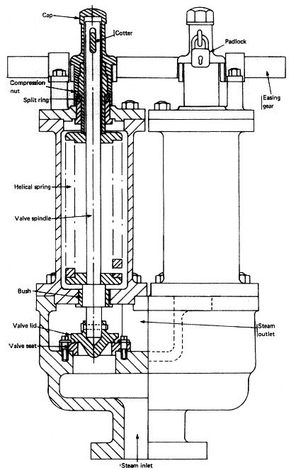
Safety Valve: Boiler safety valve is an extremely important safety equipment fitted on the steam drum of the boiler. As per SOLAS chapter II-1, every steam boiler and every un-fired steam generator shall be provided with not less than 2 safety valves of adequate capacity. However, with regards to the output or any other feature of a boiler or un-fired steam generator, the administration may permit only one safety valve to be fitted if adequate protection against overpressure is thereby satisfactorily provided.
Usually, an improved high lift is one of the most popular types of safety valves used on a ship. They are set to lift at the blow-off pressure and shut when the pressure reduces to the safe limit. They are set to open at 3 % above working pressure. The lift of valve is one-twelfth of the valve diameter.
Easing Gear: The easing gear is attached to the boiler safety valve. Every individual safety valve is provided with its own easing gear, which is a pulley and wire arrangement (connected to the lever of the safety valve) with an accessible handle at the lower operating boiler platform. It is used to lift the boiler safety valve in case of an emergency (without getting near to the safety valve) and to regularly test the operation of the safety valves.
Steam Pressure Alarm and cutout: An audio-visual alarm is also provided for the steam pressure system to remind the operator about the steam pressure. Once the alarm activates and the pressure continues to rise (or decrease), the cut-out will get activated and it will shut off the fuel burner. The cutout functioning is different and independent of the automation which operates the burner. The low-pressure cutout has an option to override it, but the high-pressure cutout will stop the burner and should never be overridden in any case
Boiler Vent: Vent on the boiler drum is required to ensure boiler does not implode once it is shut down. It is normally opened when the pressure gauge shows the reading below 0.5 bars.
Water Safety System: The water system is a high-temperature system and the level and quality of the water inside the water drum plays a crucial role in the safe operation of the boiler. Following are the equipment/system fitted on the water side of the marine boiler:
Low / high water level alarm and cutout: The boiler water drum is fitted with a level sensor, which will continuously monitor the level of water inside the drum. A full drum will carry over the water or will have no space to generate steam, thus reducing the efficiency of the boiler; whereas low or no water level in the drum will lead to over-heating of tubes and can lead to fire or meltdown of the complete boiler.
The low/ high water level provides an early warning to the operator for taking appropriate action to manage the water level inside the boiler water drum.
Too low water level alarm and shut down: The initial warning provided by the above arrangement (low/high water level alarm), may not be sufficient for the operator as there can be a major leak in the tubes, leading to a reduction in the water level. A secondary safety is therefore provided i.e. Too low water level alarm and shut down, which will stop the burner firing to control the overheating of the boiler internal parts.
Water level indicators: The boiler is fitted with multiple water level indicators to make it easy for the operator to see the water drum level and ensure operational safety of the boiler.
Local gauge glasses are provided in a duplex on the boiler drum to ensure at least one gauge glass is operational in case one stops showing the level. Remote water level indicators such as a differential pressure water level sensor, probe level sensor etc. are also provided to indicate the current level in the drum at a remote position such as the engine control room.
Salinity Sensor: The boiler drum is fitted with a salinity sensor, which continuously monitors the dissolved solids content in the water. If the solid (e.g. salt) content exceeds the set value, it trips the boiler to ensure the tubes and boiler internals does not get affected due to the contamination. The operator should either blow down the boiler and feed fresh water to the drum to eliminate the cause which is resulting in high salinity (for e.g. leakage in the condenser)
Fuel Safety System: The boiler is provided with heavy or marine gas fuel oil for generating the heat in the furnace. To ensure the fuel system is operating efficiently, it is fitted with the following boiler safety features:
Low fuel oil pressure alarm: The fuel to the burner is provided using a fuel oil pump. Two pumps areinstalled (one kept as standby) to ensure there is no operational hindrance in case of failure of one pump. If the fuel supply pressure is less than required, the atomization of fuel will not happen, leading to dripping of fuel inside the furnace. This can lead to blow-back of the burner and can seriously injure the operator. Once the low-pressure alarm is sounded, the operator must ensure to eliminate the cause behind it.
Low / high fuel oil temperature alarm: Modern marine boilers are meant to operate in different grades of fuel due to the port / ECA regulations for minimizing the air pollution from the ship. The oil temperature is an important factor as it controls the viscosity of the fuel which is directly related to atomization and efficient combustion inside the furnace. If the fuel temperature is not at its set value (which will vary for different grades), the alarm will sound. The operator must stop the alarm and the oil temperature should be brought to normal before restarting the boiler.
Smoke Density alarm: With more stringent rules coming up for environmental protection, the boiler exhaust is fitted with a smoke density sensor which detects the post-combustion product, especially during starting of a boiler and at low loads. If the smoke density is higher than the required value, it will sound an alarm to which the operator needs to check the combustion of the boiler
Operational Safety: Automation, alarms, and warnings have made the life of seafarers on ships a lot easier than what it used to be in terms of boiler safety. However, professional engineers rarely depend on them and always rely on the best practice for efficiently running the machinery.
Efficient hot well/ cascade tank function: Maintaining the correct hot-well temperature will decrease the steam production time of the boiler compared to a low-temperature water supply by the cascade tank
Routine furnace inspection: Boiler furnace is responsible to contain the heat within the boiler and to reduce the surface heat loss. Maintaining the furnace refractory will lead to efficient boiler steam production
Lagging: Once the steam comes out of the boiler via main steam stop valve, it is supplied to several systems via pipes and distribution valves. A proper lagging on the pipes and valves will ensure the boiler need not run extra as the steam loss will be contained. Also, it ensures the safety of ship staff from surface burns.
Maintenance: On-time maintenance such as testing of safety valve, cleaning of boiler tubes etc. will result in safe and efficient working of the marine boiler.

Because a safety valve is often the last device to prevent catastrophic failure under pressure conditions, it is important that the valve works at all times i.e. it must be 100% reliable.
Safety valves should be installed wherever the maximum allowable working pressure of a system or pressure containing vessel is likely to be exceeded, in particular under fault conditions due to the failure of another piece of equipment in the system.
The term “Safety Valve” and “Relief Valve” are generic terms to describe a variety of pressure relief devices. A wide range is available based on the application and required performance criteria. The different designs are required to meet numerous national standards.
The images below show the devastating results of a failed Safety valve (due to poor maintenace) or ones which have been incorrectly sized, installed or maintained.
A spring-loaded pressure relief valve which is designed to open to relieve excess pressure and to reclose and prevent the further flow of fluid after normal conditions have been restored. It is characterised by a rapid-opening "pop" action or by opening in a manner generally proportional to the increase in pressure over the opening pressure. It may be used for either compressible or incompressible fluids, depending on design, adjustment, or application.
Relief valve - A pressure relief device actuated by inlet static pressure having a gradual lift generally proportional to the increase in pressure over opening pressure.
Safety relief valve - A pressure relief valve characterised by rapid opening or pop action, or by opening in proportion to the increase in pressure over the opening pressure, depending on the application, and which may be used either for liquid or compressible fluid.
Safety valve - A valve which automatically, without the assistance of any energy other than that of the fluid concerned, discharges a quantity of the fluid so as to prevent a predetermined safe pressure being exceeded, and which is designed to re-close and prevent further flow of fluid after normal pressure conditions of service have been restored.
The images below show a standard Relief valve and a standard Safety valve from a well-known UK manufacturer. Each manufacturer does things slightly differently however all of the basic components and principles of operation are the same. As described previously, a safety valve differs from a relief valve in that it opens rapidly once the set pressure has been reached. For the same inlet size and with the valve in the closed position, the surface area that the pressure on the inlet side will see is the same. When the set pressure is reached and the valve starts to open, the disk on a Safety valve is larger (see the diagrams below) and hence the same pressure then sees a much larger surface area and consequently the force increases greatly causing the valve to open quickly and hence the characteristic pop action.
The image below shows the above Safety valves and Relief valves dismantled. The disk diameter on the 1" (DN25) Safety valve is only 7mm larger than on the Relief valve which doesnt sound like much, but when you calculate the areas it is an increase of 36%.
This diagram represents a Safety valve in its very simplest form. The force acting on the inlet side of the disk is acting against the force applied by the spring plus the force applied by the back pressure on the top of the disk.
The valve remains closed when(PI x Ab) < Fs + (PB x At), is in equilibrium when(PI x Ab) = Fs + (PB x At) and opens when(PI x Ab) > Fs + (PB x At) were PI = Inlet pressure, PB = Back pressure, At = Top of disk area, Ab = Bottom of disk area. Things to notice from this design are that if PB is variable and quite large relative to PI, then this will cause the pressure at which the valve opens to vary which is undesirable. The following two designs (Fig 3 & Fig 4) are available that eliminate the effect of back pressure on the set pressure.
The bellows prevents backpressure acting on the top side of the disk. In relation to the piston there is no top side within the main body of the valve hence again the back pressure cannot affect the set pressure. Bellows failure is an important concern in critical applications where a very precise set pressure is required. In these cases some mechanism to detect a leak of process medium out of the top vent would be implemented. Piston designs are not usually found in conventional Safety valves but are more common in Pilot Operated Safety valves.
API 520 Practice Guidelines: a conventional design should not typically be used when the built-up backpressure is greater than 10% of the set pressure at 10% over pressure. European standard EN ISO 4126: the built-up backpressure should be limited to 10% of the set pressure when the valve is discharging at the certified capacity.
In a conventional design (no bellows), the superimposed backpressure will affect the opening characteristic and set value, but the combined backpressure will alter the closing (blowdown) and re-seat value.
Overpressure is the percentage over the set pressure by which the valve is fully open. The blowdown is the percentage below the set pressure by which the valve is fully closed.
The basic elements of the design are right angle pattern valve body, inlet can be either a full nozzle or a semi-nozzle type. With a full nozzle design has the “wetted” inlet tract formed from one piece (as per figure 6) with the seat integrated into the top of the nozzle. The internal bore of the nozzle and the disc is the only part of the valve that is exposed to the process fluid with the valve in the closed position. A semi-nozzle design consists of a seating ring fitted into the body.The disc is held onto the seat by the stem, with the downward force coming from the compression on the spring mounted in the bonnet. The amount of compression on the spring is adjusted by the spring adjuster under the cap.
Unless bellows or diaphragm sealing is used, process fluid will enter the spring housing (or bonnet). The amount of fluid depends on the particular design of safety valve. If emission of this fluid into the atmosphere is acceptable, the spring housing may be vented to the atmosphere - an open bonnet. This is usually advantageous when the safety valve is used on high temperature fluids or for boiler applications as, otherwise, high temperatures can relax the spring, altering the set pressure of the valve. However, using an open bonnet exposes the valve spring and internals to environmental conditions, which can lead to damage and corrosion of the spring.
When the fluid must be completely contained by the safety valve (and the discharge system), it is necessary to use a closed bonnet, which is not vented to the atmosphere. This type of spring enclosure is almost universally used for small screwed valves and, it is becoming increasingly common on many valve ranges since, particularly on steam, discharge of the fluid could be hazardous to personnel.
A lifting mechanism is recommended to test for correct valve operation at all times where corrosion, caking, or any deposit could prevent the opening operation.
Foreign particles can lodge under the seat of the valve when it discharges. The lifting lever allows you to lift the valve and flush the obstruction. Pressure relief valves for Section VIII require a lift lever on all air, steam, and hot water valves used at temperatures over 60 degC. Typically used where periodic testing of the valve in location is desired to assure its operation. With an Open lifting lever design, when the valve discharges, fluid media will escape into the atmosphere around the open lifting lever assembly. If this is not desirable or when back pressure is present you would select a Packed Lifting Lever design.
As described above, this type is selected where leakage of the media to the atmosphere during valve discharge or during back pressure would be un-desirable. A packed lever design is a completely sealed assembly.
Some people consider a bolted and gasketed design better to the standard screw cap for applications with back pressure and / or vibration hence some manufacturers offer this as an option.
Under certain circumstances i.e. under the start-up conditions of a plant or to pressure test the system in a controlled environment, it may be required that the valve is prevented from opening.This is achieved by screwing the bolt (shown on the wire) into the cap which screws down onto the stem and prevents it lifting. Obviously it is important that test gags are removed prior to placing the valve into service.
The bellows is designed to cover the same area on the back of the disc equal to the seat area hence the back pressure will have no effect on the set pressure. See the previous section “Basic Safety Valve Principles”. Bellows also protects the spindle, spindle guide and spring from the process medium.
A disc is held against the nozzle by a spring, which is contained in a cast bonnet. The spring is adjusted by a compression screw to permit the calibration of opening or set pressure. An adjustable nozzle ring, threaded onto the nozzle, controls the geometry of the fluid exit control chamber (also known as a huddling chamber). The control chamber (huddling chamber) geometry is very important in controlling valve opening and closing pressures and stability of operation. The nozzle ring is locked into position by a ring pin assembly as shown in Figure 15 below.
Under normal system operation the valve remains in the closed position because the spring force (Fs) is greater than the system pressure acting on the internal nozzle seating area (PA). If system pressure increases to a point when these forces are equal, then the set pressure is reached. The disc lifts and fluid flows through the valve. When pressure in the system returns to a safe level, the valve closes.
Just prior to reaching set point, the pressure relief valve leaks system fluid into the huddling chamber. The fluid now acts on a larger area of the disc inside the huddling chamber (PAh), causing the valve to experience an instantaneous increase in the opening force. Refer to the figure 16 above to see relationship between Nozzle Area (A) and the Huddling Chamber Area (Ah). System pressure acting on the larger area will suddenly open the safety relief valve at a rapid rate.
Although the opening is rapid and dramatic, the valve does not open fully at set point. The system pressure must increase above set point to open the valve to its full lift and capacity position. Maximum lift and certified flow rates will be achieved within the allowable limits (overpressure) established by various codes and standards. All pressure relief ales are allowed an overpressure allowance to reach full rated flow. The allowable over pressure can vary from 10% to 21% on unfired vessels and systems, depending on the sizing basis, number of valves, and whether a fire condition is encountered.
Once the valve has controlled the pressure excursion, system pressure will start to reduce. Since the huddling chamber area is now controlling the exit fluid flow, system pressure must reduce below the set point before the spring force is able to close the valve. The difference between the set pressure and the closing pressure is called blowdown, and is usually expressed as a percentage of set pressure. The typical blowdown can vary from 7% to 10%, the industry standard.
The nozzle ring adjustment changes the shape and volume of the huddling chamber, and its position will affect both the opening and the closing characteristics of the valve. When the nozzle ring is adjusted to its top position, the huddling chamber is restricted to its maximum. The valve will usually pop very distinctly with a minimum simmer (leakage before opening), but the blowdown will increase. When the nozzle ring is lowered to its lowest position, minimal restriction to the huddling chamber occurs. At this position, simmer increases and the blowdown decreases. The final ring position is somewhere between these two extremes to provide optimal performance.
On liquid service, a different dynamic situation exists. Liquids do not expand when flowing across orifices, and a small amount of fluid flow across the nozzle will produces a large local pressure drop at the nozzle orifice. This local pressure drop causes the spring to reclose the valve if the fluid flow is minimal. Liquids leaking into the huddling chamber can quickly drain out by gravity and prevent fluid pressure from building up in the secondary area of the huddling chamber. Liquid relief valves are thus susceptible to a phenomenon called chatter, especially at low fluid flow rates. Chatter is the rapid opening and closing of the pressure relief valve and is always destructive.
Because of the difference in the characteristics of gases and liquids, some valve designs require a special liquid trim in order to meet ASME Code Section VIII performance criteria of full rated liquid flow at 10% overpressure. With liquids since no visible or audible pop is heard at set point, the set pressure is defined as the pressure when the first heavy flow occurs (a pencil sized steady stream of water that remains unbroken for approximately one inch).
Manufacturers usually state their recommended testing procedure and testing intervals in their Installation, Operating and Maintenance Instructions (IOM). Typically, they recommend a manual test every 3 or 6 months (assuming it has a lifting lever) and a set pressure test every 12 months. It is sensible to incorporate these into your maintenance plan so they are not missed. Sometimes your insurance company may require them to be tested even more regularly than this i.e. every 6 months. Testing in most cases involves removing them from your system and having them recertified in an approved workshop.
If you have a system that is shut down for annual maintenance then this is an ideal time to remove your Safety valves and have them inspected and recertified.
For systems that can only be off for short periods of time, it is sensible to keep a spare valve to swap over and then the removed valve can be inspected and recertified.
For systems that cannot be shut down, you will need to use a changeover valve which allows you to swap between Safety valves allowing one to be removed for inspection and testing.
For larger Safety valves on systems that run continuously, you may consider using in-situ testing. This method does have some limitations however since you cannot visually inspect the inside of the valve, but it will tell you if the valve is opening at the correct set pressure.
(a) A valve passing (leaking) on the outlet side when the valve is supposed to be closed. This can happen to valves of any age (new or old) and occurs if debris contained in the medium passes through the valve at a point when the valve lifts, and the debris either traps or damages the internals of the valve. On soft seated valves, hard particles may embed themselves in the soft material causing re-sealing issues. If your valve has a lifting lever and it is safe to do so, then it is worth lifting the handle for a few seconds which will hopefully clear any debris allowing the valve to reseal correctly. If this isn’t an option or it doesn’t cure the problem, then the valve will need to be removed and returned for maintenance and recertification. The time we often see this the most is during the startup of a system and there is a pressure spike, hence this is why it is extremely important that a system is flushed out well before hand.
Searching for tools to control the flow of your piping system? Explore one of the largest featured collections of products and discover a range of wholesale boiler safety valve on Alibaba.com. When you search for boiler safety valve and related items, you will be able to find many types of boiler safety valve varying in size, shape, use, and quality, all at prices in which are highly reasonable!
There are many uses of valves - mainly controlling the flow of fluids and pressure. Some examples include regulating water for irrigation, industrial uses for controlling processes, and residential piping systems. Magnetic valves like those using the solenoid, are often used in a range of industrial processes. Whereas backflow preventers are often used in residential and commercial buildings to ensure the safety and hygiene of the water supplies. Whether you are designing a regulation system for irrigation or merely looking for a new replacement, you will be able to find whatever type of boiler safety valve that you need. Our products vary from check valves to pressure reducing valves, ball valves, butterfly valves, thermostatic mixing valves, and a lot more.


 8613371530291