
cdtp safety valve in stock
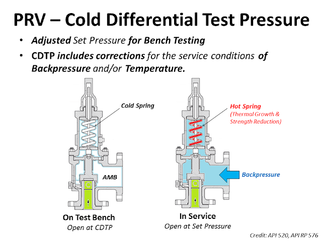
The Cold Differential Test Pressure (CDTP)of thePressure Relief Valve (PRV) is a set pressure that is adjusted to be used for the PRV (Bench Testing). Because in actual use conditions, the PRV may be affected by the Backpressure. And the operating temperature. Therefore, when testing at room temperature and without backpressure, it is necessary to adjust the set pressure to compensate for these factors. In other words, the shop test pressure = CDTP.
An example of aCold Differential Test Pressure (CDTP)with abackpressure (superimposed)effect. In this case, CDTP is equal to Set Pressure minus Backpressure.
An example of aCold Differential Test Pressure (CDTP)with different temperature compensations for use and testing. And an example ofCDTP that has been adjusted to compensate for both Backpressure (Superimposed) and temperatureeffects.
Test Stand or Test Bench is a set of equipment used for Pressure Relief Valve (PRV) in Pop Test (Set Pressure Test), Blowdown and Seat Tightness Test (Leakage Test)
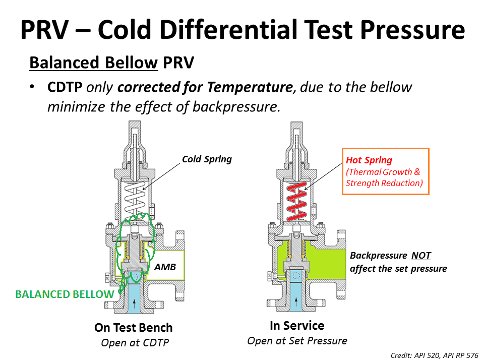
As for theBalanced Bellow Pressure Relief Valve, which has a bellowfor reducing the impact of theBackpressure, the Cold Differential Test Pressure (CDTP) of the Balanced Bellow Type PRV will compensate only for the impact of different temperatures between the Shop Test and In-service.
Built-up back pressure is the backpressure generated due to pressure losses at the outlet of an open relief valve when it is discharging. This pressure depends on the pressure of the vent header downstream to the relief valve and the relieving flowrate which is being discharged. The built-up backpressure is the pressure in the vent header plus pressure drop in the line from relief valve to vent header, when the valve is discharging at full capacity.
For certain relief valve designs, the backpressure on the valve acts as a closing force and can affect the opening pressure for the valve. ‘Conventional’ valves are highly susceptible to this effect and hence not used in applications where high backpressure is expected. ‘Balanced Bellows’ and ‘Pilot Operated’ relief valves relatively shielded from effects of high backpressure.
For some relief valves (especially conventional type relief valves), the opening of the valve is affected by backpressure seen by the valve. If the backpressure seen by such relief valves is higher than atmospheric, then it has to be designed to open at a lower differential pressure value than the relief valve set pressure minus atmospheric pressure. However when the relief valve is tested before installation, it only sees atmospheric pressure as backpressure. Hence to open this relief valve at same differential pressure value, the set point pressure for opening the valve has to be lower than original design set point pressure. This set point value is known as cold differential test pressure (CDTP).
For pilot operated and balanced bellows type relief valves, effect of backpressure on valve opening characteristics is very low and hence CDTP is the same as the original design set point pressure value.

As we had discussed the backpressure that relief valve faces in a closed system would not be present during testing in the shop and this needs to be compensated for conventional relief valves.
However as discussed above the parameter of Temperature correction factor would still be applicable to Bellows and pilot-operated relief valve if the PRV temperature is significantly different from that of ambient temperature.
Project Scenario : A Relief valve of Dresser 1900 Series (Conventional relief valve) valve is required to open at 800 Psig where the service temperature is 400°F and backpressure is 100 Psig.

Did you know, under certain circumstances, you need to verify if the Cold Differential Test Pressure (CDTP) is properly compensated for the superimposed backpressure from the flare header?
Have you come across a conventional pressure relief valve relieving to a flare header? Did you know that, under certain circumstances, you need to verify if the Cold Differential Test Pressure (CDTP) is properly compensated for the superimposed backpressure from the flare header?
API 520 Part I, Ninth Edition, Section 5.3.2.1 says, "Superimposed backpressure at the outlet of a conventional spring-loaded PRV acts to hold the valve disc closed with a force additive to the spring force. The actual spring setting can be reduced by an amount equal to the superimposed backpressure to compensate for this."
It further goes on to say in Sections 5.3.2.2 & 5.3.2.3, "Balanced spring-loaded or pilot-operated PRVs should be considered if the superimposed backpressure is variable. However, if the amount of variable superimposed backpressure is small, a conventional valve could be used provided:
For example, conventional valves are often used when the outlet is piped into a relief header without compensating the set pressures for the superimposed backpressure caused by other relieving devices. This approach can be used provided the allowable accumulation is not exceeded during the release.

Pressure at which a pressure-relief valve is adjusted to open on the test stand. NOTE The cold differential test pressure includes corrections for the service conditions of back pressure or temperature or both.

NATIONAL BOARD tells how to calculate the CDTP for a PRD taking into account a temperature differential and a back pressure, CDTP is not more than the difference of the SET PRESSURE minus the superpositions exerted by the effect of the temperature and the back pressure of a valve of conventional design (without bellows). By the way, the temperature correction is given by a multiplying factor that will depend on the quality of the internals of each valve and this is supplied by the manufacturer"s brand. For example DRESSER has its own tables of multiplying factors

Further for Convetional Valve API-521 paragraph 4.2.3.3 A convetional PRV Operating with a constant superimposed back pressure normally required a correction factor to compensate for the back pressure. In this case the required set pressure minus superimposed back pressure is equal to CDTP. This change account for the addtional closing force exerted on the valve disk by back pressure.
Now, we have to add this pressure for back pressure consideration or valve is tested based on CDTP, But if we tested based on CDTP than this is less that the set pressure as CDTP is Set Pressure - Superimposed back pressure.
Of all the challenges you face keeping your customers’ plants operating at full capacity, safety and relief valves shouldn’t be one of them. NASVI’s job is to give you the confidence that your valve supply chain is rock solid regardless the pressure it’s under.
This article is about Testing, Calibration, Inspection and POP UP test of PRVs Pressure Relief Valves and PSVs Pressure Safety Valves and International Codes and standards used for it. How to make Pressure Relief Valve Calibration Certificate and what are testing requirements for PRV and PSV. Here we explained complete steps for calibration. Question asked many times for Frequency for Pressure Relief valve as per ASME Standard.
The Scope of this procedure details the visual examination of pressure relief valve, adjustment of set pressure (pop up) / seat tightness (if required). This procedure defines steps to perform testing & inspection of Safety & Pressure Relief Valves subject to the requirements.
He shall be responsible for monitoring safely aspects and ensuring that the testing activity is done in accordance with JGC/DEC Safety Standard Procedure. He shall discuss with the workers the characteristics of related materials and status of work area giving reminders as an additional point to work safely.
Bellows valves shall be checked to ensure the bonnet vent is open or piped to a safe location. The vent shall not be plugged since this will cause the valve set pressure to be high if the bellows
Check that inlet and discharge piping are not placing excessive stress on the valve body which can lead to distortion of the valve body and leakage or malfunction.
Check the condition and adequacy of piping supports. Discharge piping should be supported independent of the valve itself. Check for possible hazards to personnel from the valve discharge or discharge pipe.
Check that there are no intervening isolation valves between the pressure source and the valve inlet or between the valve outlet and its point of discharge. (Isolation valves may be permitted in some pressure vessel service. Isolation valves are not permitted for power boilers, heating boilers, or water heaters.)
On the test bench, Seat Leakage Test can be performed by increasing the pressure on the valve to 90% of the CDTP and observing the discharge side of the valve for evidence of leakage.
For a valve with set pressure greater than 50 psi, the leakage rate in bubbles per minute shall be determined with test pressure at the valve inlet held at 90 % of the set pressure.
For a valve with set pressure greater than 50 psi, the leakage rate in bubbles per minute shall be determined with test pressure at the valve inlet held at 90 % of the set pressure.
When the machine is used by someone who is not trained, when improper use is made on the machine. The consequences of improper operation of the machine, in particular the negligence of the safety regulations are:
For Oversize Valves: Both side of the valves is fitted with Blind Flange of relevant rating and required pressure to be applied from main unit and it’s not required any separate manifold or relief valve.
No. of Valves more than one: At the time of 4 or 5 valves to be fitted with required bolt, nut, gasket at one time and both end of the valves is fitted with Blind Flange of relevant rating and required pressure to be applied from main unit and it’s not required any separate manifold or relief valve.
For Control & Shut off valves: The valve is clamped from the inlet on the test port and the outlet of the valves is fitted with Blind flange of relevant rating and it’s not required any separate manifold or relief valve.
For Oversize Valves: Both side of the valves is fitted with Blind Flange of relevant rating and required pressure to be applied from main unit and it’s not required any separate manifold or relief valve.
No. of Valves more than one: At the time of 4 or 5 valves to be fitted with required bolt, nut, gasket at one time and both end of the valves is fitted with Blind Flange of relevant rating and required pressure to be applied from main unit and it’s not required any separate manifold or relief valve.


 8613371530291