
cdtp safety valve free sample
Built-up back pressure is the backpressure generated due to pressure losses at the outlet of an open relief valve when it is discharging. This pressure depends on the pressure of the vent header downstream to the relief valve and the relieving flowrate which is being discharged. The built-up backpressure is the pressure in the vent header plus pressure drop in the line from relief valve to vent header, when the valve is discharging at full capacity.
For certain relief valve designs, the backpressure on the valve acts as a closing force and can affect the opening pressure for the valve. ‘Conventional’ valves are highly susceptible to this effect and hence not used in applications where high backpressure is expected. ‘Balanced Bellows’ and ‘Pilot Operated’ relief valves relatively shielded from effects of high backpressure.
For some relief valves (especially conventional type relief valves), the opening of the valve is affected by backpressure seen by the valve. If the backpressure seen by such relief valves is higher than atmospheric, then it has to be designed to open at a lower differential pressure value than the relief valve set pressure minus atmospheric pressure. However when the relief valve is tested before installation, it only sees atmospheric pressure as backpressure. Hence to open this relief valve at same differential pressure value, the set point pressure for opening the valve has to be lower than original design set point pressure. This set point value is known as cold differential test pressure (CDTP).
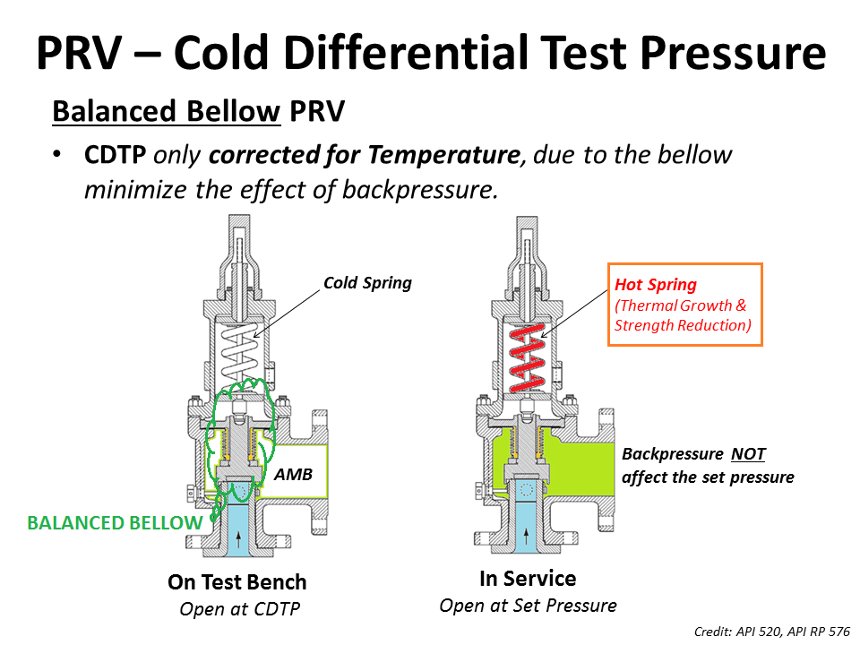
For pilot operated and balanced bellows type relief valves, effect of backpressure on valve opening characteristics is very low and hence CDTP is the same as the original design set point pressure value.
As we had discussed the backpressure that relief valve faces in a closed system would not be present during testing in the shop and this needs to be compensated for conventional relief valves.
However as discussed above the parameter of Temperature correction factor would still be applicable to Bellows and pilot-operated relief valve if the PRV temperature is significantly different from that of ambient temperature.
Project Scenario : A Relief valve of Dresser 1900 Series (Conventional relief valve) valve is required to open at 800 Psig where the service temperature is 400°F and backpressure is 100 Psig.
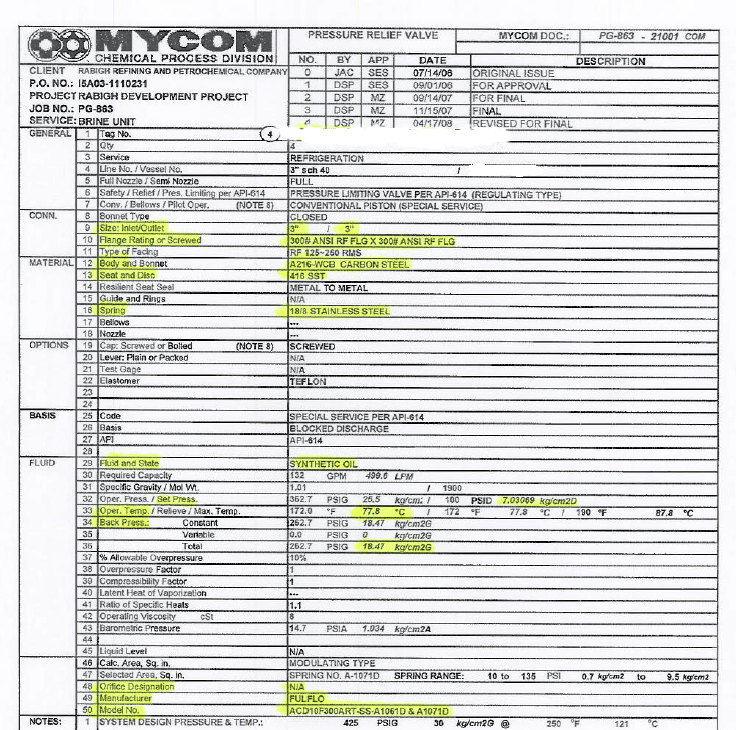
I think that CDTP has been used for set pressure. The data sheet should state both. Set pressure would be 25.5 but this value is stated as the operating pressure.
Note also. The subject Fulflo valves are Hydraulic Bypass Relief Valves and not of the API-520/-526 Pressure Relief Valve variety. A PRV data sheet has been used.
Yes, it is a conventional piston type pressure limiting valve. Set pressure is mentioned as differential pressure. i.e, 7.03 Kg/cm2D. Constant back pressure is 18.47 Kg/cm2g. Presently the valve set in the RV shop test stand is 7.03 kg/cm2g. Our concern is, we would like to know, whether the CDTP value is correct or not? As mentioned by " The Obturator" , I think, set pressure should be mentioned as 25.5 Kg/cm2g instead of 7.03 kg/cm2g. RE: CDTP for Fulflo valve
API 520 part 1 says that the CDTP temperature correction is required when the relieving temperature exceeds 250 F however, my practice with Crosby has showed that when the OPERATING NOT RELIEVING temperature is > 150 F, the correction factor is required, u may find it in Installation manual of the relevant manufacturer i think
3) If the valve is balanced, u have to only consider the temperature correction factors in the case of CROSBY. Not sure about the manufacturer u mentioned
for Anderson greenwood 400 series, piston type modulating valve, i couldn"t find any correction factory in the datasheet also checked with the software by increasing the both relieving and operating temperature to 250 F seems no correction is required , however, api says that u have to consult with the manufacturer RE: CDTP for Fulflo valve
“The Fulflo valves operate on differential pressures but temperature normally doesn’t affect the set pressure at which the valve will open as the valve set pressure and then relieves.”
My concern is how to calculate the CDTP. We have more than 7500 PSVs in our plant. But only these two PSVs having concern, how to calculate the CDTP. In all other PSVs data sheet, set pressure is mentioned in kg/cm2g engineering unit, but in these two pzvs, set pressure is kg/cm2D (Differential pressure).
At present, we have mentioned the CDTP as 7.03 kg/cm2g. As we considered as Set pressure is 25.5 kg/cm2g & constant back pressure is 18.47 kg/cm2g. As mentioned above by " The Obturator" , set pressure should be mentioned as 25.5 Kg/cm2g instead of 7.03 kg/cm2g.
Regarding also your attached manufacturers chart. It is incomplete. For example, for Crosby, that is the chart for J series (JOS-E/JBS-E). For steam and other valve types the compensation chart is different. The chart also fails to advise that the compensation factor applies to operating temperatured (too many users have taken relief temperature - note Tai incorrectly state this - see API-520).
The temperature compensation factor should be outlined in the manufacturers IOM, The Obturator correctly points out that this should be based on operating not relieving temperature as the impact of the thermal effect will not be observed unless the spring is normally exposed to the high temperature. RE: CDTP for Fulflo valve
“4.2.3.3 The temperature used for the correction factor should be based on the temperature at the inlet to the relief valve at its normal service (nonrelieving) conditions
and also used in sizing software programs (ie: PRV2SIZE, etc.) are based on operating temperature at the valve normal service (nonrelieving) conditions.
As per previous Saudi Aramco pzv procedure, for Crosby PZVs, relieving temperature will be considered as operating temperature, while calculating the temperature compensation. May be you have noticed the highlighted portion from the procedure screen shot. Based on API update, it was updated. Now for any manufacturer pzvs, operating temperature will be considered for CDTP.

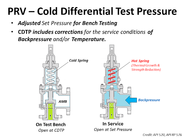
The Cold Differential Test Pressure (CDTP)of thePressure Relief Valve (PRV) is a set pressure that is adjusted to be used for the PRV (Bench Testing). Because in actual use conditions, the PRV may be affected by the Backpressure. And the operating temperature. Therefore, when testing at room temperature and without backpressure, it is necessary to adjust the set pressure to compensate for these factors. In other words, the shop test pressure = CDTP.
An example of aCold Differential Test Pressure (CDTP)with abackpressure (superimposed)effect. In this case, CDTP is equal to Set Pressure minus Backpressure.
An example of aCold Differential Test Pressure (CDTP)with different temperature compensations for use and testing. And an example ofCDTP that has been adjusted to compensate for both Backpressure (Superimposed) and temperatureeffects.
Test Stand or Test Bench is a set of equipment used for Pressure Relief Valve (PRV) in Pop Test (Set Pressure Test), Blowdown and Seat Tightness Test (Leakage Test)
As for theBalanced Bellow Pressure Relief Valve, which has a bellowfor reducing the impact of theBackpressure, the Cold Differential Test Pressure (CDTP) of the Balanced Bellow Type PRV will compensate only for the impact of different temperatures between the Shop Test and In-service.

A question we commonly receive is why a valve appears to open, or actuate, earlier than expected. Often, we find that the valve is not, in fact, opening early. Rather, the perception that it is actuating early is due to a misunderstanding of set pressure.
The set pressure, also called the opening pressure, of a safety or relief valve is the inlet pressure at which the valve begins to open as required by code.
A valve should be set to open at the maximum allowable working pressure (MAWP) of the vessel the valve is intended to protect. There is some tolerance to actual set pressure, which means that a valve set at 100 psig may open slightly above or slightly below this level.
The first step is to determine if your valve really is opening early. Sometimes safety and safety relief valves appear to open before they reach the set pressure — there may be an audible or visible release of fluid between the seat and the disc. This is known as “simmer” or “warn,” and it is not the same as a full open.
Simmer, or warn, occurs when a valve opens slightly, discharging only a small percentage of its rated capacity. For example, direct spring-operated safety valves may simmer or warn at 90% of the nameplate set pressure. A valve that is simmering is not considered open.
The next step is to check your gauge to ensure that it is reporting the set pressure correctly. The gauge should be calibrated properly and located upstream of the valve, close to the valve inlet. Rapid increases in system pressure can make it appear that a valve is opening early because the gauge can’t accurately report the pressure.
If you still believe your valve is opening early, assess the operating factors that might be contributing to the situation. Valves are factory set using standard conditions, and factors like high temperature, vibration, and back pressure can cause them to open early. These conditions can be compensated for using cold set pressure, aka cold differential test pressure (CDTP). Learn more about CDTP from the National Board.

This article is about Testing, Calibration, Inspection and POP UP test of PRVs Pressure Relief Valves and PSVs Pressure Safety Valves and International Codes and standards used for it. How to make Pressure Relief Valve Calibration Certificate and what are testing requirements for PRV and PSV. Here we explained complete steps for calibration. Question asked many times for Frequency for Pressure Relief valve as per ASME Standard.
The Scope of this procedure details the visual examination of pressure relief valve, adjustment of set pressure (pop up) / seat tightness (if required). This procedure defines steps to perform testing & inspection of Safety & Pressure Relief Valves subject to the requirements.
He shall be responsible for monitoring safely aspects and ensuring that the testing activity is done in accordance with JGC/DEC Safety Standard Procedure. He shall discuss with the workers the characteristics of related materials and status of work area giving reminders as an additional point to work safely.
Bellows valves shall be checked to ensure the bonnet vent is open or piped to a safe location. The vent shall not be plugged since this will cause the valve set pressure to be high if the bellows
Check that inlet and discharge piping are not placing excessive stress on the valve body which can lead to distortion of the valve body and leakage or malfunction.
Check the condition and adequacy of piping supports. Discharge piping should be supported independent of the valve itself. Check for possible hazards to personnel from the valve discharge or discharge pipe.
Check that there are no intervening isolation valves between the pressure source and the valve inlet or between the valve outlet and its point of discharge. (Isolation valves may be permitted in some pressure vessel service. Isolation valves are not permitted for power boilers, heating boilers, or water heaters.)
On the test bench, Seat Leakage Test can be performed by increasing the pressure on the valve to 90% of the CDTP and observing the discharge side of the valve for evidence of leakage.
For a valve with set pressure greater than 50 psi, the leakage rate in bubbles per minute shall be determined with test pressure at the valve inlet held at 90 % of the set pressure.
For a valve with set pressure greater than 50 psi, the leakage rate in bubbles per minute shall be determined with test pressure at the valve inlet held at 90 % of the set pressure.
When the machine is used by someone who is not trained, when improper use is made on the machine. The consequences of improper operation of the machine, in particular the negligence of the safety regulations are:
For Oversize Valves: Both side of the valves is fitted with Blind Flange of relevant rating and required pressure to be applied from main unit and it’s not required any separate manifold or relief valve.
No. of Valves more than one: At the time of 4 or 5 valves to be fitted with required bolt, nut, gasket at one time and both end of the valves is fitted with Blind Flange of relevant rating and required pressure to be applied from main unit and it’s not required any separate manifold or relief valve.
For Control & Shut off valves: The valve is clamped from the inlet on the test port and the outlet of the valves is fitted with Blind flange of relevant rating and it’s not required any separate manifold or relief valve.
For Oversize Valves: Both side of the valves is fitted with Blind Flange of relevant rating and required pressure to be applied from main unit and it’s not required any separate manifold or relief valve.
No. of Valves more than one: At the time of 4 or 5 valves to be fitted with required bolt, nut, gasket at one time and both end of the valves is fitted with Blind Flange of relevant rating and required pressure to be applied from main unit and it’s not required any separate manifold or relief valve.


 8613371530291