
cormack propane safety valve factory

Outside the contiguous United States, a 5% discount will be given on orders shipping to Alaska, Hawaii, US Virgin Islands (St. Croix, St. Thomas, St. John, and the Water Island), Puerto Rico, and Guam. All other orders are shipped FOB from a Northern Safety & Industrial warehouse, unless otherwise specified

Forklift Accessories Disclaimer. This device may not comply with your forklift regional/provincial standards. Modifications and additions to the lift truck that affect capacity or safe operation shall not be performed without the written approval of the forklift manufacturer. Where such modifications and additions are performed, capacity, operation and maintenance instruction plates, tags or decals shall be changed accordingly. A pre-use examination shall take place in accordance with CSA safety standard for lift trucks. We will not be held responsible for any loss or damage or misuse that this product has or may have caused.
Changing a LPG cylinder on a forklift can sometimes give a forklift operator a big surprise! The seal in the cylinder valve can fail causing liquid propane gas to spray over the hand or face faster than they can react. Liquid propane vaporizes quickly (-42 degrees C or -44 degrees F) and will cause extreme frostbite if it contacts the skin.
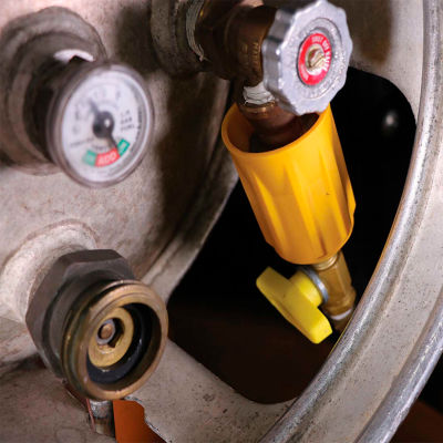
The Solution: Placing a shut-off valve on the hose with the Propane Coupler to prevent the LPG from escaping back on to the forklift operator and escaping in to the surrounding environment.
Once the propane coupler has been installed and the lever is then opened the lever handle will prevent anyone from removing the Propane coupler. The lever must be closed before the propane coupler can be loosened off.

Changing an LPG (Liquid Petroleum Gas, otherwise known as Propane) cylinder can injure a forklift operator if the seal in the cylinder valve has failed, as a defective seal can allow the liquid propane gas to spray over the hand or face of the operator. Since liquid propane vaporizes quickly (-44° F or -42° C), it will cause extreme frostbite when in contact with the skin. The solution is to place this shut-off valve on the hose, preventing the liquid propane from coming back onto the operator. When closed, the valve shuts off LP Gas to the coupler preventing gas from coming back through the hose if the seal fails. This is important, as most LPG forklift cylinders are rented and the operator does not know the condition of the seal or age of the cylinder without rigorous inspection. When the valve is open, the high-visibility shut-off handle covers the coupler so that the valve cannot be disconnected. Quick and easy installation.

Of all the challenges you face keeping your customers’ plants operating at full capacity, safety and relief valves shouldn’t be one of them. NASVI’s job is to give you the confidence that your valve supply chain is rock solid regardless the pressure it’s under.
Changing a LPG (liquid Propane gas) cylinder can sometimes give a forklift operator a big surprise! The seal in the cylinder valve can fail causing liquid propane gas to spray over the hand or face faster than they can react. Liquid propane vaporizes quickly (-42°C or -44°F) and will cause extreme frostbite if it touches skin. Almost every forklift operator has had a negative experience and they do not like getting hit with LP gas!

Eaton’s bidirectional disconnect switches incorporate the latest switching technology to enhance operator safety, extend equipment life, and reduce installation costs in grounded and ungrounded systems. The bidirectional disconnect switches can switch one circuit per pole and remove polarity limitations. The switches are available at 30, 90, and 100 amperes, with either 600 Vdc or 1,000 Vdc configurations. These new switches are available for either grounded or ungrounded PV Systems and are capable of breaking up to six circuits with one switch. Grounded system switches include individual, isolate terminals for landing the grounded conductors.
The Safety Sentry Warning Signal Alarm improves loading dock safety by alerting those nearby a vehicle backing into the dock position. The Safety Sentry utilizes a 105 dB siren and strobe light combination system with industrial motion sensing technology. The patent-pending design is rated NEMA 4 and constructed with UV-resistant polycarbonate using liquid tight strain relief connections.
The Guardian Defender combines safety interlock switches/controls capable of achieving up to PLe, Category 4 level safety with a movable physical barrier restricting access to dangerous machine movement. At the same time, process driven hazards such as weld flash, sparks, flying debris, mist, spray, and smoke are contained. The Guardian Defender’s switches/controls provide clear visual communications with two signals, green for safe and red for unsafe. The machine is designed with a 9-in. foam soft bottom edge and Armorplex curtain material.
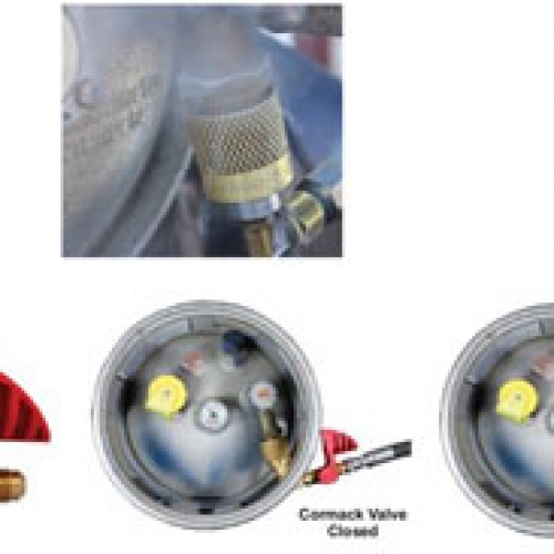
Cormack Propane Safety Valve helps prevent LPG escaping when changing forklift cylinders. When the Cormack valve is closed, it shuts off LP Gas next to the coupler to prevent it from coming through if the seal fails. If the Cormack valve is open, the foolproof handle design covers the coupler so the operator cannot disconnect it in the open position. The Cormack valve fits almost all forklifts and increases LPG cylinder exchange safety. With installation only taking minutes, LPG cylinder changes are quicker.
DETEX Belt Dressing is a metal detectable plastic aerosol component for the food industry, designed to assist food processing plants in meeting strict HACCP requirements. Blue colored caps, actuators, and extension tubes signify the DETEX components, which are metal detectable and can help prevent food from being contaminated. All metal detectable plastic component ingredients are GRAS listed, meeting the FDA requirements as an acceptable material for use in food processing plants. The aerosol can is in compliance with the Food Safety Net Services and contains lithographed labels.
The Miller QuickPick Rescue Kit delivers peace-of-mind during unexpected, peer-rescue situations involving those working at height. The rescuer can attach the system to the suspended worker while remaining securely anchored on the working surface. All rescue components are included in an easy-to-store kit with no required assembly. The kit is available in two configurations: the Premium Miller QuickPick Kit designed for workers whose job is not normally rescue, and the Standard Miller QuickPick Kit designed for those experienced in rescue situations. The kits are a professional solution that enhance worker safety and comply with corporate fall protection plans.
The GateKeeper Mezzanine Safety Gate is a reciprocating barrier that creates a controlled access area where workers can safely load and unload from the edge of a mezzanine, pick module, or other elevated platforms. The barrier designed with the GateKeeper is interconnected and cannot be open at the same time. When the outer gate opens to allow pallets to enter the mezzanine level, the inner gate automatically closes, keeping workers out. The exclusive link bar design ensures that both gates always work in unison, without relying on the chains or cables. Also featured with the GateKeeper is a Saf-T-Latch, preventing workers from raising the outer gate while inside the work zone.
The RHR-4000 Dok-Lok vehicle restraint adds another layer of safety by securing overseas container chassis, which can have a plate of obstruction above the rear impact guard. The RHR-4000 offers a water- and dust-resistant IP66 rated motor and a longer lasting, corrosive-resistant finish that meets the ASTM B117 testing standard. Like previous Dok-Loks, the RHR-4000 helps prevent all types of trailer separation accidents, including early departure and landing gear collapse, as well as trailer creep, pop-up, upending, and tip over. The Dok-Lok rotating hook restraints are designed for impact and to withstand the loading dock environment.
Siemens introduced the SIMATIC STEP 7 Safety Advanced V11 option as a part of its Totally Integrated Automation (TIA) Portal, providing end users with all configuration and programming tools required for generating a fail-safe program. The TIA Portal integrates product and production engineering via one interface, linking all of Siemens automation software packages and platforms. The framework of the TIA Portal enables all Siemens Programmable Controllers, HMI operator panel, and drives to be configured in the same development environment. The new Safety Advanced feature allows for intuitive operation and quick entry into the generation of fail-safe programs.

When you choose propane forklifts, you have choices for refueling — both of which your propane supplier can help you navigate safely. You can choose a cylinder exchange program, where your propane supplier refills the cylinders for you. Or you can choose on-site refueling, where trained members of your team refill cylinders themselves.

Fork lift trucks typically use pressurized tanks filled with propane gas (or natural gas) as a fuel source to operate the internal combustion engine of the vehicle. The use of propane gas or natural gas for such vehicles is desirable in order to reduce or control emissions of combustion products in their useful environment such as warehouses and the like. Typically, a pressurized, propane gas tank is mounted on a lift truck, for example, and attached to a fuel line that, in turn, is connected to the internal combustion engine of the lift truck. The pressurized fuel tank is typically removable and replaceable and includes enough pressurized fuel to operate the truck for a full shift or an eight hour day. However, the operator of the lift truck cannot always predict when and where the fuel in the tank will be consumed and exhausted. Thus, it may be necessary to tow the lift truck back to a refueling center where the empty propane fuel tank is removed and replaced by a full tank. Alternatively, the empty propane fuel tank from the fork lift truck may be removed and carried to a filling station for refilling and return.
In review, on standard fork lift trucks in most warehouses in the United States, the usual fuel utilized by the truck is propane gas and/or natural gas. The gas is provided from a refillable portable tank which is supported or mounted on the truck and which is replaced from time to time as the tank becomes empty. For maximum utilization, a lift truck is operated until its tank becomes empty. At that time, the operator typically removes the empty tank and physically carries it to a storage area where it is exchanged for a full tank and carried back to the lift truck, mounted on the truck, and attached to the proper fuel line. Alternatively, the lift truck can be towed to the fuel tank storage area.
In any event, fuel tank replacement is a time consuming job and may take upwards of thirty minutes in order to complete. Consequently, a system devised to reduce the time for exchanging fillable portable fuel tanks for lift trucks and for other vehicles is desirable. Thus, there has developed a need for an improved fueling system for fork lift trucks and other vehicles such as prime movers, automobiles, trucks and buses, and vehicles of the type which use propane gas or natural gas provided from a pressurized portable or replaceable fuel tank.
Briefly, the present invention comprises an auxiliary fuel tank which is maintained permanently on board a vehicle such as a lift truck. The tank is connected through a fill line to the fuel feed line that normally provides fuel to the engine from a portable, replaceable, main, fuel tank. The connection to the fuel feed line is through a tee connection, or tee. A check valve permits fuel in the fuel feed line from the portable fuel tank to flow unidirectionally into the auxiliary fuel tank when the portable tank is initially attached or mounted on the vehicle. Once the fuel pressure in the auxiliary tank and the portable tank are equalized (indicating that the auxiliary tank has been substantially filled with propane or natural gas) a valve mechanism is operated to isolate the auxiliary fuel tank from the fuel feed system to the engine. The valve mechanism remains in the “off” position until the portable, main fuel tank supply is exhausted. Thereafter, the valve mechanism is opened and a fuel line from the auxiliary tank feeds fuel into the engine directly through a separate line or through the main fuel feed line. This enables the truck operator to continue operation of the lift truck for a short time period and also permits the operator to move the truck to a refueling station where the portable fuel tank may be replaced. The capacity of the auxiliary fuel tank is typically at least 2% of the capacity of the portable fuel tank, but less than 10%. This enables the vehicle or truck to have an auxiliary fuel supply for at least 10-15 minutes of operation thus permitting an operator in a warehouse adequate time to move the vehicle expeditiously to a refueling center.
A further object of the invention is to provide an auxiliary fuel tank which is automatically filled upon placement of a portable fuel tank on the vehicle with the opening of a manual valve interconnecting the portable tank and the auxiliary fuel tank.
Yet, another object of the invention is to provide an auxiliary fuel tank which is isolated by means of a manually operated valve mechanism subsequent to being filled from a portable fuel tank through interconnecting lines that connect to the auxiliary tank as well as the engine of the vehicle.
FIG. 1 is an isometric view of a typical lift truck incorporating a portable, main fuel tank as well as the permanent auxiliary fuel tank and interconnecting lines, valves and other mechanism associated therewith;
FIG. 1 depicts a typical fork lift truck 10 of the type which utilizes propane gas cylinders or tanks as a source of the fuel for the internal combustion engine which drives the truck. Thus, a truck 10 includes a fork lift mechanism 12. The fork lift truck 10 also includes an internal combustion engine, schematically illustrated as engine 14. A fuel line 16 provides propane fuel through a regulator 18 from a portable, removable, main propane tank 20. Typically the tank 20 will include adequate propane fuel or natural gas fuel for operating the engine 14 of the fork lift truck 10 for a full eight hours in a warehouse environment. The tank 20 is removably mounted on a deck 22 of the truck 10 and is thus replaceable whenever fuel is exhausted therefrom. In addition, the fork lift truck 10 includes a bracket or cage 24 on deck 22. The bracket or cage 24 serves multiple functions of providing roll bar protection for the operator of the truck 10, a mount for auxiliary fuel tank as described below, and protection for the main tank 20.
FIG. 2 illustrates a first embodiment of the invention. The cage or bracket 24 includes opposed, spaced uprights 28 and 30 and a top, protective cross brace 32. Tank 20, which is the removable or portable tank, is positioned intermediate the uprights 28 and 30 and beneath the cross bracket or brace 32 on the deck 22. In this fashion, the portable tank 20 is protected in the event of rollover or some other accident which might expose the tank 20. Thus, tank 20 is mounted in a typical manner on the fork lift truck 10 with a connection fitting 34 adapted for connection with a fuel line 36 to the engine 14. Typically the fitting 34 includes a manually operable valve which remains closed until connected to the line 36. The fitting 34 may also have a quick connect feature.
The line 36 is connected to a tee 38. The tee 38 includes an inlet 40, a first outlet 42 and a second outlet 44. The first outlet 42 connects through a unidirectional check valve 46 which provides for fuel flow in the direction indicated by the arrow in FIG. 1. The check valve 46 feeds into main fuel line 48 which, in turn, connects through an inlet 50 of a tee 52. The tee 52 includes an outlet 54 connected to engine fuel line 56 which connects through a regulator 58 that controls fuel pressure to engine 14.
The spare or auxiliary tank 26 is permanently mounted on an upright 28. A draw tube 59 extends into tank 26. The auxiliary tank 26 further includes a high pressure release valve 60 designed to release the pressure from the tank 26 in the event the pressure exceeds a predetermined value. The tank 26 further includes a manual shut off valve 62 connected to the high pressure relief valve 60. A safety collar 61 on the tank 26 protects the valve 60 and valve 62. The manual shut off valve 62 is normally maintained in the open position and is an extra safety feature. An auxiliary fuel line 64 connects from valve 62 to an inlet 66 of a tee 68. The tee 68 further includes an inlet 70 through line 72 from the outlet 44 of tee 38. Intermediate the outlet 44 in fuel line 72 is a check valve 74. Check valve 74 permits unidirectional flow therethrough to the auxiliary tank 26 by way of the tee 68.
The tee 68 further includes an outlet 76 connected to an auxiliary fuel line 78 that is directed through a valve mechanism 80 having an outlet line 82 to inlet 84 of the tee 54. Normally, the valve mechanism 80 is in the closed position so that when the portable tank 20 is attached to the system, propane fuel will flow through the check valve 74 into the tank 26 and pressurize the tank 26. The auxiliary fuel line 78 will also be pressurized, but fuel will not be able to flow to the regulator 58 through line 78. However, propane from the portable tank 20 will also flow through the check valve 46 and through the regulator 58 via the described line 48, tee 52 and line 58.
When the fuel in tank 20 is exhausted, the operator of the fork lift truck or the vehicle merely opens the valve mechanism 80. This permits auxiliary fuel to flow through that valve 80 and through the tee 52 to the regulator 58 and then to the engine 14. The check valve 46 will prevent back flow into the tank 20 as will the check valve 74. The auxiliary fuel tank 26 may thus be utilized to provide fuel to the engine 14 until tank 20 is replaced. When the tank 20 is to be removed, the valve mechanism 80 is closed. The propane tank 20 is removed and replaced. Upon replacement of propane tank 20, valve mechanism 80 is closed and fuel will then flow through check valve 74 into the auxiliary fuel tank 26 permanently mounted on upright 28. In this manner, the fuel in the auxiliary tank 26 is replenished after usage and subsequent to exhaustion of the fuel in the removable, portable tank 20. After tank 26 is filled as described, the system is ready for operation.
FIG. 3 discloses a second embodiment of the auxiliary fuel system of the invention. In FIG. 3, like components are labeled with like numbers. Thus, replaceable, portable tank 20 connects through a connection fitting 34. Auxiliary fuel tank 26 is mounted on an upright (not shown), The emergency shut off valve 62 is combined with a high pressure relief valve 64. The fuel from the tank 20 as well as the tank 26 ultimately feeds into a fuel line 56 that connects with a fuel regulator 58 in the line connected to the engine 14. In the embodiment of FIG. 3, however, the main portable tank 20 connects through a check valve 86 and a tee 88 having an inlet 90 and an outlet 92 to the line 56. The other outlet or branch 94 of the tee 88 is connected to the auxiliary tank 26 through a line 96 manual valve mechanism 98 and line 100. With the design of FIG. 3, the manual valve mechanism 98 is maintained in the open position upon initial attachment of the propane or natural gas tank 20. Gas will then flow through the check valve 86 and through the manual valve 98 to fill the auxiliary or spare tank 26. Valve 98 may then be closed. Fuel will likewise thus flow through the tee 88 to the regulator 58 to provide fuel to the engine 14. When fuel is exhausted in tank 20, valve mechanism 98 is open to permit fuel to flow through the tee 88 to the regulator 28. Check valve 86 prevents back flow into the tank 20. The cylinder or tank 20 may then be replaced. FIG. 4 illustrated yet a further embodiment of the invention wherein like components are labeled with like numbers. Thus, the portable, replaceable tank 20 provides fuel through a connection 34 and a check valve 86 to a tee 88 connected to a line 56 feeding into a regulator 58 in the fuel line to the engine 14. Auxiliary tank 26 connects through an emergency shut off 62 and a high pressure release valve 64 to the tee 88. In this circumstance, the emergency shut off valve 62 is maintained in the open position upon initial attachment of the portable tank 20 to the system. Thereafter, the emergency shut off valve 62 should be turned to the “off” position until auxiliary fuel is required. When auxiliary fuel is required, the valve mechanism or shut off 62 is opened to provide auxiliary fuel through the regulator 58. Again, check valve 86 precludes back flow of fuel into the tank or cylinder 20.
With the present invention, the size of the spare or auxiliary fuel tank 26 is designed and provided to include, at least typically, more than about 2% of the volume of gas stored in the portable tank 20. Preferably, approximately 8% to 10% of the fuel would be maintained in the auxiliary tank 26. The auxiliary tank 26 also may include an indicator which indicates the amount of fuel retained therein and the pressure of the fuel. The spare tank 26 may be mounted on the inside of the upright, to further enhance the installation safety of the auxiliary tank system. The high pressure relief valve 64 need not necessarily be included in the outlet line of the tank 26. It can be attached at some other outlet opening from the tank 26. With the described system, down time previously allotted for portable tank 20 replacement is significantly reduced, resulting in operating cost savings and increased operating efficiency.
It is possible to vary the construction of the fuel tank system without departing from the spirit and scope of the invention. The system can be incorporated in other types of vehicles other than fork lift trucks. However, it is especially appropriate and useful in combination with a fork lift truck of the type using propane or natural gas as a fuel. Thus, while there has been set forth preferred embodiments of the invention, it is to be understood that the invention is limited only by the following claims and equivalents thereof.

Houses or buildings utilizing gas energy require a gas piping system to power heaters, ovens, and other heating appliances. One of the most important elements of a gas piping system is the propane service valve, which controls propane gas flow in and out of a building. While there may be many other valves within gas plumbing, this valve functions as an on/off switch and serves as the main point of control for cutting off or allowing for the flow of gas into a piping system.
Propane valves are simply used to turn gas on or off. Similar to that of a water faucet, propane valves consist of a handwheel that controls propane gas flow when turned. When the wheel is turned, a stem and seat mechanism located within the valve opens or closes to prevent or allow gas flow from the tank.
Using propane gas requires an LP gas regulator, which decreases the amount of pressure released into the gas line, keeping it at an acceptable and safe level while still meeting the needs of the application.
There are multiple different valves in any propane system, each of which has a particular job. At IPS Equipment, we provide some of the most common types of valves for propane systems, including:
A pressure or safety relief valve is a safety mechanism that every propane system needs. It allows excess pressure in the tank to be slowly and safely released. Without this valve, pressure can build up and cause the tank to crack or rupture.
The relief valve has a pressurized spring. If the pressure levels within the tank grow too high, the spring forces the valve open just enough to return the pressure levels to acceptable levels. Once the pressure decreases, the spring relaxes, and the valve automatically closes.
This valve is where gas delivery personnel add new gas to a propane tank. Propane delivery trucks have hoses that can be attached to the filler valve so propane can be pumped into the tank. This valve is also pressure-activated, and it opens automatically in response to the pressure in the hose.
Filler valves have gaskets that operators can push the hose end against to avoid propane leaks. They also only allow for unidirectional fluid movement, meaning that once the tank is full, there is no risk of propane escaping when the hose is withdrawn.
This shut-off valve prevents gas from entering the building and any attached appliances. You can use this central point of control like an on/off switch to completely halt the path of gas in the system.
This valve is also called a vapor return valve or vapor eliminator valve. It ensures that propane is delivered at the proper pressure levels from the propane delivery truck to a personal tank and returns any excess propane back to the delivery truck. This is similar to a safety valve, except the vapor equalizing valve ensures the propane is delivered at proper pressures for optimum use, not safety. This is especially crucial during hot weather or in warm environments, as that can increase the pressure.
This specialized valve is meant for use by propane companies only. It allows operators with the proper tools to drain liquid propane from the tank. Propane tanks must be drained to <5% capacity levels before they can legally be moved.
IPS Equipment specializes in supplying propane marketers with reliable valves, fittings, regulators, and more for propane systems. Contact us today to learn more about our comprehensive products or services, or browse through our catalog to start your order.

The safety relief valve is one of the most important and vital valves on any LP Gas container. All propane tanks and cylinders are required by law to be fitted with pressure relief devices designed to relieve excess pressure. The function of a safety relief valve is to keep a propane tank from rupturing in the unlikely event of excessive pressure buildup. Propane tank relief valves are also known as pop off valves, pressure venting valves or relief valves.
Relief valves are held in the closed position by the force of a powerful spring. As long as the pressure inside the tank is less than that of the spring, the valve will remain closed. If tank pressure rises to that of the spring, the valve will open resulting in a hissing sound outside the tank. If the pressure in the tank rises significantly higher than that of the spring, the valve will fully open. When the valve fully opens, it initially makes a loud pop followed by a blast of released propane gas. Once the pressure is released and the tank pressure falls below that of the spring, the valve closes.
Most propane tanks in residential and commercial service have internal safety relief valves. The reason for an internal valve as opposed to an external pressure relief valve is it presents less of an obstruction when moving the tank. Internal relief valves are generally placed near the end of the propane tank on above ground containers.
Found primarily on older tanks, external relief valves operate in the same manner as an internal relief valve with the spring mechanism being outside the propane tank itself. Relief valves on multvalves are always fitted with external safety relief valves. Older tanks with an external relief valve installed on the container are generally replaced with internal pressure relief valves, provided they are connected to a dedicated tank opening specifically designed for the placement of the relief valve.
Because the safety relief valve performs such a vital role in the protection of the propane tank, it should be maintained and repaired by licensed propane professionals only. Do not ever look into a relief valve or stand over it.
A protective cover should be placed over the relief valve to ensure proper operation. If the valve has debris in the upper mechanism of the relief valve and it opens, the debris may cause the valve to remain open resulting in a potentially dangerous situation and/or excessive loss of propane. A simple protective relief valve cover can be made from a plastic bag fastened around the external portion of the valve with a rubber band.
If a you encounter a relief valve that seems to be "hissing" (opened to relieve pressure) do not tap it or mess with it. If the tank has been recently filled in hot weather and the face gauge reads over 80 or 85%, spray some water from a hose on the tank. This may cool it down and reduce the expansion of the liquid in the tank. Call your propane company immediately and inform them of the situation.
Pictured here is a relief valve that was apparently leaking. Instead of calling the propane company to replace the valve, the customer decided to fix the problem himself. Using a soldering iron, he soldered the leak until it stopped leaking. In the process of "repairing" the leak, the customer completely sealed the relief valve in a closed position placing himself and his family in a very dangerous situation.
In this type of situation, a relief valve that is sealed shut will not allow the tank to vent excess pressure if it is overfilled or the pressure inside the tank exceeds the working pressure of the container. In a case where the tank is unable to vent to the outside, the tank is subject to rupturing causing more harm and damage than money saved by trying to fix it yourself. Let the propane company or LPG professional handle any problems with thesafety relief valve.

One thing you should pay attention to is the propane tank’s safety relief valve. All propane tanks, including the cylinders you use for your BBQ grill, are required by law to have pressure relief devices to allow for the release of excess pressure in the tank.
A spring keeps the safety relief valve closed as long as the pressure inside the tank is at a safe level. If the pressure in the tank reaches the same amount of pressure of the spring, the safety relief valve is opened. If that happens, you’ll hear a hissing sound coming from the tank. In instances where the pressure in the tank is much higher than that of the spring, the valve will fully open. You’ll hear pop if that occurs.
Your propane tank needs to have room for the propane inside it to expand. That is why your propane tank is filled to 80% of its capacity. The 20% of the tank that is empty space allows the propane to safely expand.
That expansion is why propane tanks are white or beige. Light colors reflect heat to minimize expansion. Dark colors retain heat and can cause the propane inside your tank to expand to dangerous levels. So, even if your propane tank doesn’t go with the color of your siding, leave it alone.


 8613371530291