
dead weight safety valve brands
With wide and rich industrial experience, we are able to offer the best in class Dead Weight Safety Valves. These valves are used in industrial boilers for safety purpose and ensure safety by releasing excess pressure. Provided valve is highly recognized for high performance, requires less maintenance and smooth operations. Our offered safety valve is made available in number of specifications for our clients to choose from. Our valued clients can avail these Dead Weight Safety Valves from us at market leading price.

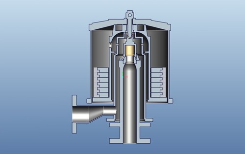
To prevent damage to the tank and help ensure safe operations, the Alfa Laval SB Pressure Relief Valve protects a pressurized tank during an overpressure event. It is designed for hygienic processes in the brewery, dairy, food and beverage industries. The valve can be integrated with a SCANDI BREW® tank top system.
The advantages of an integrated Pressure Relief Valve are lower initial costs, superior hygiene and smaller area required for the valve. The size and setting of the Pressure Relief Valve is based on the tank design data and process requirements.
Level and Flow Control Engineers manufacturing and exporting Dead Weight Safety Valves which is mainly used in the Power Plants, CPP, Sugar Plants for Low Pressure applications. Brand Name : Beekay-Made in INDIa
If you rate our Dead Weight Safety Valve on attributes such as ergonomics and operational efficiency, you will find it right there at the top of the class. We have used only the highest quality materials and components in manufacturing our Valve assembly, which exhibits in the performance. No denying, we are among the leading manufacturers, exporters and suppliers from Chennai, Tamil Nadu.

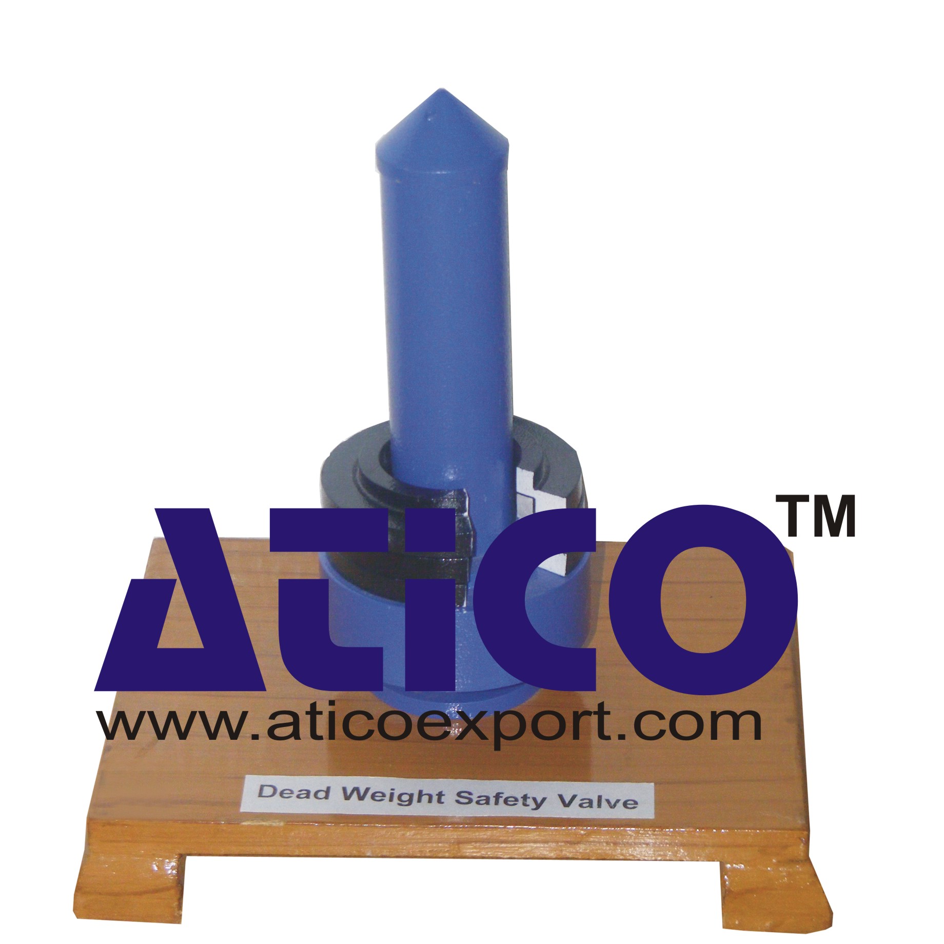
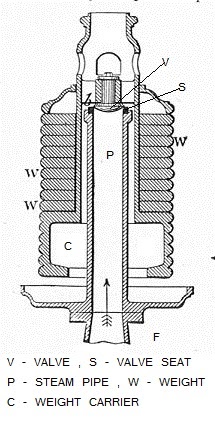
afety valve consists of a valve seat where the pressure in the boiler or pressure vessel when it exceeds the normal working pressure lifts the valve seat with its weight. The excess pressure fluid therefore escapes through the pipe to the atmosphere, until the pressure reaches its normal value. It is the simplest type of safety valve; it is suitable for stationary boilers and pressure vessels only, because it cannot withstand the jerks and vibration of mobile boilers or pressure vessels. Another disadvantage of this valve is the heavy weight required to balance the pressure. Hence, it is not suitable for high pressure boilers.

There is a wide range of safety valves available to meet the many different applications and performance criteria demanded by different industries. Furthermore, national standards define many varying types of safety valve.
The ASME standard I and ASME standard VIII for boiler and pressure vessel applications and the ASME/ANSI PTC 25.3 standard for safety valves and relief valves provide the following definition. These standards set performance characteristics as well as defining the different types of safety valves that are used:
ASME I valve - A safety relief valve conforming to the requirements of Section I of the ASME pressure vessel code for boiler applications which will open within 3% overpressure and close within 4%. It will usually feature two blowdown rings, and is identified by a National Board ‘V’ stamp.
ASME VIII valve- A safety relief valve conforming to the requirements of Section VIII of the ASME pressure vessel code for pressure vessel applications which will open within 10% overpressure and close within 7%. Identified by a National Board ‘UV’ stamp.
Full bore safety valve - A safety valve having no protrusions in the bore, and wherein the valve lifts to an extent sufficient for the minimum area at any section, at or below the seat, to become the controlling orifice.
Conventional safety relief valve -The spring housing is vented to the discharge side, hence operational characteristics are directly affected by changes in the backpressure to the valve.
Balanced safety relief valve -A balanced valve incorporates a means of minimising the effect of backpressure on the operational characteristics of the valve.
Pilot operated pressure relief valve -The major relieving device is combined with, and is controlled by, a self-actuated auxiliary pressure relief device.
Power-actuated safety relief valve - A pressure relief valve in which the major pressure relieving device is combined with, and controlled by, a device requiring an external source of energy.
Standard safety valve - A valve which, following opening, reaches the degree of lift necessary for the mass flowrate to be discharged within a pressure rise of not more than 10%. (The valve is characterised by a pop type action and is sometimes known as high lift).
Full lift (Vollhub) safety valve -A safety valve which, after commencement of lift, opens rapidly within a 5% pressure rise up to the full lift as limited by the design. The amount of lift up to the rapid opening (proportional range) shall not be more than 20%.
Direct loaded safety valve -A safety valve in which the opening force underneath the valve disc is opposed by a closing force such as a spring or a weight.
Proportional safety valve - A safety valve which opens more or less steadily in relation to the increase in pressure. Sudden opening within a 10% lift range will not occur without pressure increase. Following opening within a pressure of not more than 10%, these safety valves achieve the lift necessary for the mass flow to be discharged.
Diaphragm safety valve -A direct loaded safety valve wherein linear moving and rotating elements and springs are protected against the effects of the fluid by a diaphragm
Bellows safety valve - A direct loaded safety valve wherein sliding and (partially or fully) rotating elements and springs are protected against the effects of the fluids by a bellows. The bellows may be of such a design that it compensates for influences of backpressure.
Controlled safety valve - Consists of a main valve and a control device. It also includes direct acting safety valves with supplementary loading in which, until the set pressure is reached, an additional force increases the closing force.
Safety valve - A safety valve which automatically, without the assistance of any energy other than that of the fluid concerned, discharges a quantity of the fluid so as to prevent a predetermined safe pressure being exceeded, and which is designed to re-close and prevent further flow of fluid after normal pressure conditions of service have been restored. Note; the valve can be characterised either by pop action (rapid opening) or by opening in proportion (not necessarily linear) to the increase in pressure over the set pressure.
Direct loaded safety valve -A safety valve in which the loading due to the fluid pressure underneath the valve disc is opposed only by a direct mechanical loading device such as a weight, lever and weight, or a spring.
Assisted safety valve -A safety valve which by means of a powered assistance mechanism, may additionally be lifted at a pressure lower than the set pressure and will, even in the event of a failure of the assistance mechanism, comply with all the requirements for safety valves given in the standard.
Supplementary loaded safety valve - A safety valve that has, until the pressure at the inlet to the safety valve reaches the set pressure, an additional force, which increases the sealing force.
Note; this additional force (supplementary load), which may be provided by means of an extraneous power source, is reliably released when the pressure at the inlet of the safety valve reaches the set pressure. The amount of supplementary loading is so arranged that if such supplementary loading is not released, the safety valve will attain its certified discharge capacity at a pressure not greater than 1.1 times the maximum allowable pressure of the equipment to be protected.
Pilot operated safety valve -A safety valve, the operation of which is initiated and controlled by the fluid discharged from a pilot valve, which is itself, a direct loaded safety valve subject to the requirement of the standard.
The common characteristic shared between the definitions of conventional safety valves in the different standards, is that their operational characteristics are affected by any backpressure in the discharge system. It is important to note that the total backpressure is generated from two components; superimposed backpressure and the built-up backpressure:
Subsequently, in a conventional safety valve, only the superimposed backpressure will affect the opening characteristic and set value, but the combined backpressure will alter the blowdown characteristic and re-seat value.
The ASME/ANSI standard makes the further classification that conventional valves have a spring housing that is vented to the discharge side of the valve. If the spring housing is vented to the atmosphere, any superimposed backpressure will still affect the operational characteristics. Thiscan be seen from Figure 9.2.1, which shows schematic diagrams of valves whose spring housings are vented to the discharge side of the valve and to the atmosphere.
By considering the forces acting on the disc (with area AD), it can be seen that the required opening force (equivalent to the product of inlet pressure (PV) and the nozzle area (AN)) is the sum of the spring force (FS) and the force due to the backpressure (PB) acting on the top and bottom of the disc. In the case of a spring housing vented to the discharge side of the valve (an ASME conventional safety relief valve, see Figure 9.2.1 (a)), the required opening force is:
In both cases, if a significant superimposed backpressure exists, its effects on the set pressure need to be considered when designing a safety valve system.
Once the valve starts to open, the effects of built-up backpressure also have to be taken into account. For a conventional safety valve with the spring housing vented to the discharge side of the valve, see Figure 9.2.1 (a), the effect of built-up backpressure can be determined by considering Equation 9.2.1 and by noting that once the valve starts to open, the inlet pressure is the sum of the set pressure, PS, and the overpressure, PO.
Balanced safety valves are those that incorporate a means of eliminating the effects of backpressure. There are two basic designs that can be used to achieve this:
Although there are several variations of the piston valve, they generally consist of a piston type disc whose movement is constrained by a vented guide. The area of the top face of the piston, AP, and the nozzle seat area, AN, are designed to be equal. This means that the effective area of both the top and bottom surfaces of the disc exposed to the backpressure are equal, and therefore any additional forces are balanced. In addition, the spring bonnet is vented such that the top face of the piston is subjected to atmospheric pressure, as shown in Figure 9.2.2.
The bellows arrangement prevents backpressure acting on the upper side of the disc within the area of the bellows. The disc area extending beyond the bellows and the opposing disc area are equal, and so the forces acting on the disc are balanced, and the backpressure has little effect on the valve opening pressure.
Bellows failure is an important concern when using a bellows balanced safety valve, as this may affect the set pressure and capacity of the valve. It is important, therefore, that there is some mechanism for detecting any uncharacteristic fluid flow through the bellows vents. In addition, some bellows balanced safety valves include an auxiliary piston that is used to overcome the effects of backpressure in the case of bellows failure. This type of safety valve is usually only used on critical applications in the oil and petrochemical industries.
Since balanced pressure relief valves are typically more expensive than their unbalanced counterparts, they are commonly only used where high pressure manifolds are unavoidable, or in critical applications where a very precise set pressure or blowdown is required.
This type of safety valve uses the flowing medium itself, through a pilot valve, to apply the closing force on the safety valve disc. The pilot valve is itself a small safety valve.
The diaphragm type is typically only available for low pressure applications and it produces a proportional type action, characteristic of relief valves used in liquid systems. They are therefore of little use in steam systems, consequently, they will not be considered in this text.
The piston type valve consists of a main valve, which uses a piston shaped closing device (or obturator), and an external pilot valve. Figure 9.2.4 shows a diagram of a typical piston type, pilot operated safety valve.
The piston and seating arrangement incorporated in the main valve is designed so that the bottom area of the piston, exposed to the inlet fluid, is less than the area of the top of the piston. As both ends of the piston are exposed to the fluid at the same pressure, this means that under normal system operating conditions, the closing force, resulting from the larger top area, is greater than the inlet force. The resultant downward force therefore holds the piston firmly on its seat.
If the inlet pressure were to rise, the net closing force on the piston also increases, ensuring that a tight shut-off is continually maintained. However, when the inlet pressure reaches the set pressure, the pilot valve will pop open to release the fluid pressure above the piston. With much less fluid pressure acting on the upper surface of the piston, the inlet pressure generates a net upwards force and the piston will leave its seat. This causes the main valve to pop open, allowing the process fluid to be discharged.
When the inlet pressure has been sufficiently reduced, the pilot valve will reclose, preventing the further release of fluid from the top of the piston, thereby re-establishing the net downward force, and causing the piston to reseat.
Pilot operated safety valves offer good overpressure and blowdown performance (a blowdown of 2% is attainable). For this reason, they are used where a narrow margin is required between the set pressure and the system operating pressure. Pilot operated valves are also available in much larger sizes, making them the preferred type of safety valve for larger capacities.
One of the main concerns with pilot operated safety valves is that the small bore, pilot connecting pipes are susceptible to blockage by foreign matter, or due to the collection of condensate in these pipes. This can lead to the failure of the valve, either in the open or closed position, depending on where the blockage occurs.
The terms full lift, high lift and low lift refer to the amount of travel the disc undergoes as it moves from its closed position to the position required to produce the certified discharge capacity, and how this affects the discharge capacity of the valve.
A full lift safety valve is one in which the disc lifts sufficiently, so that the curtain area no longer influences the discharge area. The discharge area, and therefore the capacity of the valve are subsequently determined by the bore area. This occurs when the disc lifts a distance of at least a quarter of the bore diameter. A full lift conventional safety valve is often the best choice for general steam applications.
The disc of a high lift safety valve lifts a distance of at least 1/12th of the bore diameter. This means that the curtain area, and ultimately the position of the disc, determines the discharge area. The discharge capacities of high lift valves tend to be significantly lower than those of full lift valves, and for a given discharge capacity, it is usually possible to select a full lift valve that has a nominal size several times smaller than a corresponding high lift valve, which usually incurs cost advantages.Furthermore, high lift valves tend to be used on compressible fluids where their action is more proportional.
In low lift valves, the disc only lifts a distance of 1/24th of the bore diameter. The discharge area is determined entirely by the position of the disc, and since the disc only lifts a small amount, the capacities tend to be much lower than those of full or high lift valves.
Except when safety valves are discharging, the only parts that are wetted by the process fluid are the inlet tract (nozzle) and the disc. Since safety valves operate infrequently under normal conditions, all other components can be manufactured from standard materials for most applications. There are however several exceptions, in which case, special materials have to be used, these include:
Cast steel -Commonly used on higher pressure valves (up to 40 bar g). Process type valves are usually made from a cast steel body with an austenitic full nozzle type construction.
For all safety valves, it is important that moving parts, particularly the spindle and guides are made from materials that will not easily degrade or corrode. As seats and discs are constantly in contact with the process fluid, they must be able to resist the effects of erosion and corrosion.
The spring is a critical element of the safety valve and must provide reliable performance within the required parameters. Standard safety valves will typically use carbon steel for moderate temperatures. Tungsten steel is used for higher temperature, non-corrosive applications, and stainless steel is used for corrosive or clean steam duty. For sour gas and high temperature applications, often special materials such as monel, hastelloy and ‘inconel’ are used.
Standard safety valves are generally fitted with an easing lever, which enables the valve to be lifted manually in order to ensure that it is operational at pressures in excess of 75% of set pressure. This is usually done as part of routine safety checks, or during maintenance to prevent seizing. The fitting of a lever is usually a requirement of national standards and insurance companies for steam and hot water applications. For example, the ASME Boiler and Pressure Vessel Code states that pressure relief valves must be fitted with a lever if they are to be used on air, water over 60°C, and steam.
A test gag (Figure 9.2.7) may be used to prevent the valve from opening at the set pressure during hydraulic testing when commissioning a system. Once tested, the gag screw is removed and replaced with a short blanking plug before the valve is placed in service.
The amount of fluid depends on the particular design of safety valve. If emission of this fluid into the atmosphere is acceptable, the spring housing may be vented to the atmosphere – an open bonnet. This is usually advantageous when the safety valve is used on high temperature fluids or for boiler applications as, otherwise, high temperatures can relax the spring, altering the set pressure of the valve. However, using an open bonnet exposes the valve spring and internals to environmental conditions, which can lead to damage and corrosion of the spring.
When the fluid must be completely contained by the safety valve (and the discharge system), it is necessary to use a closed bonnet, which is not vented to the atmosphere. This type of spring enclosure is almost universally used for small screwed valves and, it is becoming increasingly common on many valve ranges since, particularly on steam, discharge of the fluid could be hazardous to personnel.
Some safety valves, most commonly those used for water applications, incorporate a flexible diaphragm or bellows to isolate the safety valve spring and upper chamber from the process fluid, (see Figure 9.2.9).
Sri Venkat Engineers was started in the year 2014, are manufacturing a wide array of Industrial Valves and Strainers. Offered products range consists of Strainer Manufacturer, Industrial Type Valves, and Duplex Type Strainers. In adding to this, these products are applauded by our customers for user-friendly, strong construction, low maintenance, sturdy design, and longer service life. To meet our customers" needs, we bring forth our products with the qualitative configuration in a convenient way.
We have capable professionals who work in close adroitness with clientele to accomplish the demands. Highly experienced employee, they are chosen on the basis of their understanding and work hard to achieve the growth of our organization. Apart from this, industrial valves and strainers offered by us are strictly tested on different parameters in obedience to the set industry norms.
Our mentor Mr. S. Venkatesh maintains friendly relations in the company to undertake bulk orders in a proficient manner. He always guides us to deliver high-quality industrial valves and strainers to the patrons.
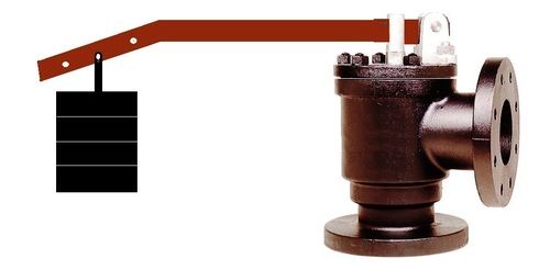
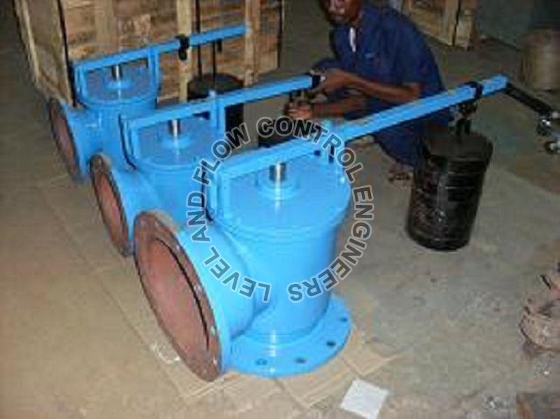
LFCE manufacturing and exporting dead weight safety valve and pressure relief valves to the process industry. It low cost and high efficiency valves which can work for slurry and high viscosity fluids.
Out side weight can be moved forward and downward to adjust the set pressure. Pressure 0 to 10 bar and size 25NB to 500NB bigger sizes available on request
Design Standardas per API,ANSI,ASME,DIN,BSLFCE manufacturing and exporting dead weight safety valve and pressure relief valves to the process industry. It low cost and high efficiency valves which can work for slurry and high viscosity fluids.
Out side weight can be moved forward and downward to adjust the set pressure. Pressure 0 to 10 bar and size 25NB to 500NB bigger sizes available on request
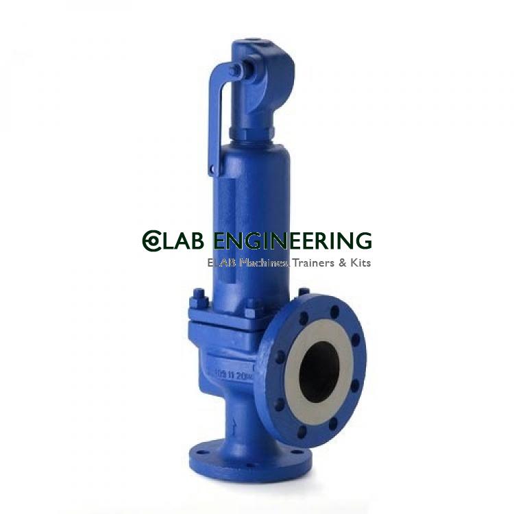
TemperatureUpto 300 Deg CWe are the manufacturer, and exporter of Dead Weight Safety Valves from Chennai-India to Globally are spring loaded right angled which are used in the pressure vessels, pipelines, and reactors to control the excess pressures. If the pressure exceeds the set point then the valves can open and close automatically as per the pre-settled pressure ratios. Hence the capital equipment is in safe.
Asafety valveis a device that prevents a system from overpressurizing. It consists of a valve with a spring-loaded mechanism that increases in force when the pressure exceeds a preset limit. It is generally used in compressed air or fluid systems. In some cases, it can prevent overpressure from resulting in system failures. This design of safety valves helps prevent disasters.
Safety valves come in three basic types. These include heavy hammer lever, spring, and pulse valves. The heavy hammer lever type of valve uses a lever or a heavy hammer to balance the force on the valve flap. The principle behind this type of safety valve is called leverage, which means it can use a small weight to exert a large amount of force. This type of safety valve also allows you to adjust the opening pressure.
What are the different types of safety valves available? Here is a quick breakdown. A safety valve can be a spring-loaded valve; a Lever loaded valve, or a dead-weight safety-weight valve. The main differences between these valves are the mechanism by which they work and how they function. Spring-loaded safety valves can be easily adjusted. A lever-loaded safety-weight valve is generally less expensive.
There are several types of safety valves. One of them is a dead-weight safety valve. A dead weight safety valve is a safety valve that relies on a heavy disc that acts as a weight against a valve seat to prevent overpressure. A dead weight safety valve is a good choice for low-pressure vessels. Unlike other safety valves, dead weight safety valves do not have a spring. The weight of the disc acts to adjust the valve seat. When the pressure on the valve exceeds the normal pressure limit, it discharges the excess steam through a pipe.
The core of any safety valve is the spring. It must be durable and conform to all the specified requirements, including temperature and working medium. The spring material must be corrosion-resistant. For moderate temperature applications, carbon steel is used. For higher temperature and corrosive duty applications, tungsten steel or stainless steel is used. If the temperature is extremely high, special materials are used. Whether the safety valve is used in the air or water, it must be certified.
When purchasing a safety valve, you will find that there are several different options. Some safety valves have manual operation options. Typically, the manual operation will be performed during routine safety checks or maintenance. The actual flowing capacity will be reduced by 10%. The derated coefficient of discharge will also be calculated. As with most safety valves, there are several terms and definitions that are not included in the DIN 3320 standard.
Generally, a boiler will be fitted with high steam and low water safety valve. The low water safety valve is a combination of two valves. It operates when the water level in the boiler drops below a predetermined level. When the level drops too low, the lever safety valve operates, blowing with a loud noise. Fig. 5-4 shows how these safety valves work. They are located on the top or side of the boiler and are attached to the fire box or furnace.

We LFCE are manufacture and Exporter of BeeKay Pressure Relief Valves globally which is used to release the excess pressure in the tanks and vessels to prevent from explosions.
Our Safety valve, Safety Relief Valve, Dead Weight Safety Valves are most accurate in Set pressure Opening and Re-Setting within 5% to 10% of Accumulation and Blow Down.
We are the manufacturer, supplier and exporter of Breather Valves from Chennai-India to Globally are extensively used for automatic venting and for conservation of losses due to evaporation. Breather valves minimizes the risk of fire, explosion and collapsing of tank by relieving automatically the dangerous pressure and vacuum occurring in the tank due to any reason. Products are mainly used in the low pressure tanks and vessels.
We are the manufacturer, supplier and exporter of Pressure Relief Valves from Chennai-India to Globally are spring loaded right angled which are used in the pressure vessels, pipelines and reactors to control the excess pressures. If the pressure is exceed the set point then the valves can open and close automatically as per the pre-settled pressure ratios. Hence the capital equipment are in safe.
We are the manufacturer, supplier and exporter of Safety Valves from Chennai-India to Globally. Used for controlling excess pressures, their precision construction standards make them extensively used in equipment like pressure vessels, pipelines & reactors.
We are the manufacturer, supplier and exporter of Gauge Glass Valves from Chennai-India to Globally and cocks for the sake of market demands. Gauge glass valves are widely used across the industries because it is a convenient tool to visually monitor the liquid level in tanks. Its rigid construction produces corrosion resistance and its compact design permits it to be safely located close to the tank. Our skilled workforce is capable enough to customize as per client"s requirements.
We are the manufacturer, supplier and exporter of SafetyRelief Valvefrom Chennai-India to Globally are spring loaded-right angled which are used in the pressure vessels, pipelines, and reactors to control the excess pressures. If the pressure exceeds the set point then the safety and relief valves can open and close automatically as per the pre-settled pressure ratios. Hence the capital equipment are in safe.
We are the manufacturer, supplier and exporter of Tank Breather Valve. Spring Loaded-right angled safety valves & safety relief valves in Chennai and India. Used for controlling excess pressures, their precision construction standards make them extensively used in equipment like pressure vessels, pipelines & reactors.
We are the manufacturer, supplier and exporter of Vacuum Relief Valve from Chennai-India to Globally. Clients in a wide range of spring loaded-right angled safety valves & safety relief valves. Used for controlling excess pressures, their precision construction standards make them extensively used in equipment like pressure vessels, pipelines & reactors.
We are the manufacturer, supplier and exporter of SafetyRelief Valves from Chennai-India to Globally are spring loaded-right angled which are used in the pressure vessels, pipelines, and reactors to control the excess pressures. If the pressure exceeds the set point then the safety and relief valves can open and close automatically as per the pre-settled pressure ratios. Hence the capital equipment are in safe.
We are manufacturer and exporter of Pressure Relief Valve, Safety Valves, Pressure cum Vaccum Relief Valves, Vaccum Relief Valves. Our range of Products are mainly exported to Europe and South Asian Countries and Gulf Countries. Pressure Relief Valve is mainly used in the Pressure Vessels, Boilers, Pipelines, and Other Big Storage Tanks. If the Pressure is exceed the limit. Valve automatically open and reset for the related pressure.
We are the manufacturer, supplier and exporter of Pressure Relief Valves from Chennai-India to Globally are spring loaded right angled which are used in the pressure vessels, pipelines and reactors to control the excess pressures. If the pressure is exceed the set point then the valves can open and close automatically as per the pre-settled pressure ratios. Hence the capital equipment are in safe.
LEVEL AND FLOW CONTROL ENGINEERS manufacturing and Exporting Safety Relief Valve under the Brand name of BEEKAY - Made in INDIA which is well know in the process industry. Safety Relief Valves are used in the Pipe lines, Pumps, Compressor, Boiler, Tanks, Reactors.
LFCE manufacturing, supplying and exporting Dead Weight Safety Valve and Safety Relief Valves under brand name BEEKAY. Dead weight safety valve is most suitable for Low Pressures and slurry, high viscosity applications. Set Pressures are adjustable very easy by moving weight front and back.
Level and Flow Control Engineers Manufacturing Dead Weight Safety Valve and Safety Relief Valves as per API standards which is meant for Low Pressure applications. Cost effective and easy pressure adjustments without opening of the valve. Weight will be adjusted thro the Lever.
LEVEL AND FLOW manufacturing and exporting Air Valves are designed to withstand vibrations, therefore it is unaffected by any external vibrations. Valve finds application of automatic venting of air in large size water distribution pipes (e.g. distribution manifolds in the central system) and in all cases where it is necessary to eliminate large quantities of air from the system. Valve opening and closing is determined by the float movement (up-down). When there is air in the Pipeline (or) in the Capital Equipments, the force of the float weight acts on the lever which is integral with the plug, thus causing it to move down. In such situation the seat is free and allows the air to be vented outside. Due to this the Pipeline or the capital equipment is safe without any airlocks.
We are the manufacturer, supplier and exporter of Direct mechanical lever operated Ball Float Valves from Chennai-India to Globally, single or double ported in C.I.,C.S., and SS, non metallic constructions operating mechanism is specially designed to be mounted on all types of tank equipment and serves the purpose of a liquid level controlling. Automatic filling and maintaining is done at the said levels.
Clients in a wide range of spring loaded-right angled safety valves & safety relief valves. Used for controlling excess pressures, their precision construction standards make them extensively used in equipment like pressure vessels, pipelines & reactors.
We are the manufacturer, supplier and exporter of Ball Float Valve in Chennai-India to Globally is a cost effective level control device for water or non hazardous liquids. The ball float valves may be mounted inside the tank.
We are the manufacturer, and exporter of Dead Weight Safety Valves from Chennai-India to Globally are spring loaded right angled which are used in the pressure vessels, pipelines and reactors to control the excess pressures. If the pressure is exceed the set point then the valves can open and close automatically as per the pre-settled pressure ratios. Hence the capital equipment are in safe. We are majorly looking inquiries from Dubai, Abu Dhabi, Sharjah, UAE, Kuwait, Oman, Qatar, Egypt, Thailand, Indonesia, Singapore, Malaysia, Myanmar, Vietnam, Brunei, Australia, Europe, Italy, Belgium.

Pressure relief valves (safety relief valves) are designed to open at a preset pressure and discharge fluid until pressure drops to acceptable levels. The development of the safety relief valve has an interesting history.
Denis Papin is credited by many sources as the originator of the first pressure relief valve (circa 1679) to prevent overpressure of his steam powered “digester”. His pressure relief design consisted of a weight suspended on a lever arm. When the force of the steam pressure acting on the valve exceeded the force of the weight acting through the lever arm the valve opened. Designs requiring a higher relief pressure setting required a longer lever arm and/or larger weights. This simple system worked however more space was needed and it coud be easily tampered with leading to a possible overpressure and explosion. Another disadvantage was premature opening of the valve if the device was subjected to bouncing movement.
Direct-acting deadweight pressure relief valves: Later to avoid the disadvantages of the lever arrangement, direct-acting deadweight pressure relief valves were installed on early steam locomotives. In this design, weights were applied directly to the top of the valve mechanism. To keep the size of the weights in a reasonable range, the valve size was often undersized resulting in a smaller vent opening than required. Often an explosion would occur as the steam pressure rose faster than the vent could release excess pressure. Bouncing movements also prematurely released pressure.
Direct acting spring valves: Timothy Hackworth is believed to be the first to use direct acting spring valves (circa 1828) on his locomotive engine called the Royal George. Timothy utilized an accordion arrangement of leaf springs, which would later be replaced with coil springs, to apply force to the valve. The spring force could be fine tuned by adjusting the nuts retaining the leaf springs.
Refinements to the direct acting spring relief valve design continued in subsequent years in response to the widespread use of steam boilers to provide heat and to power locomotives, river boats, and pumps. Steam boilers are less common today but the safety relief valve continues to be a critical component, in systems with pressure vessels, to protect against damage or catastrophic failure.
Each application has its own unique requirements but before we get into the selection process, let’s have a look at the operating principles of a typical direct acting pressure relief valve.
In operation, the pressure relief valve remains normally closed until pressures upstream reaches the desired set pressure. The valve will crack open when the set pressure is reached, and continue to open further, allowing more flow as over pressure increases. When upstream pressure falls a few psi below the set pressure, the valve will close again.
Most commonly, pressure relief valves employ a spring loaded “poppet” valve as a valve element. The poppet includes an elastomeric seal or, in some high pressure designs a thermoplastic seal, which is configured to make a seal on a valve seat. In operation, the spring and upstream pressure apply opposing forces on the valve. When the force of the upstream pressure exerts a greater force than the spring force, then the poppet moves away from the valve seat which allows fluid to pass through the outlet port. As the upstream pressure drops below the set point the valve then closes.
Piston style designs are often used when higher relief pressures are required, when ruggedness is a concern or when the relief pressure does not have to be held to a tight tolerance. Piston designs tend to be more sluggish, compared to diaphragm designs due to friction from the piston seal. In low pressure applications, or when high accuracy is required, the diaphragm style is preferred. Diaphragm relief valves employ a thin disc shaped element which is used to sense pressure changes. They are usually made of an elastomer, however, thin convoluted metal is used in special applications. Diaphragms essentially eliminate the friction inherent with piston style designs. Additionally, for a particular relief valve size, it is often possible to provide a greater sensing area with a diaphragm design than would be feasible with a piston style design.
The reference force element is usually a mechanical spring. This spring exerts a force on the sensing element and acts to close the valve. Many pressure relief valves are designed with an adjustment which allows the user to adjust the relief pressure set-point by changing the force exerted by the reference spring.
The chemical properties of the fluid should be considered before determining the best materials for your application. Each fluid will have its own unique characteristics so care must be taken to select the appropriate body and seal materials that will come in contact with the fluid. The parts of the pressure relief valve in contact with the fluid are known as the “wetted” components. If the fluid is flammable or hazardous in nature the pressure relief valve must be capable of discharging it safely.
In many high technology applications space is limited and weight is a factor. Some manufactures specialize in miniature components and should be consulted. Material selection, particularly the relief valve body components, will impact weight. Also carefully consider the port (thread) sizes, adjustment styles, and mounting options as these will influence size and weight.
In many high technology applications space is limited and weight is a factor. Some manufactures specialize in miniature components and should be consulted. Material selection, particularly the relief valve body components, will impact weight. Also carefully consider the port (thread) sizes, adjustment styles, and mounting options as these will influence size and weight.
A wide range of materials are available to handle various fluids and operating environments. Common pressure relief valve component materials include brass, plastic, and aluminum. Various grades of stainless steel (such as 303, 304, and 316) are available too. Springs used inside the relief valve are typically made of music wire (carbon steel) or stainless steel.
Brass is suited to most common applications and is usually economical. Aluminum is often specified when weight is a consideration. Plastic is considered when low cost is of primarily concern or a throw away item is required. Stainless Steels are often chosen for use with corrosive fluids, when cleanliness of the fluid is a consideration or when the operating temperatures will be high.
The materials selected for the pressure relief valve not only need to be compatible with the fluid but also must be able to function properly at the expected operating temperature. The primary concern is whether or not the elastomer chosen will function properly throughout the expected temperature range. Additionally, the operating temperature may affect flow capacity and/or the spring rate in extreme applications.
Beswick Engineering manufactures four styles of pressure relief valves to best suit your application. The RVD and RVD8 are diaphragm based pressure relief valves which are suited to lower relief pressures. The RV2 and BPR valves are piston based designs.
... -start valve with Series MX2 air treatment units without the need for additional connection interfaces. The soft-start valve is positioned upstream of the safety valves, ...
Two hands safety valve, which allows a safety use of two hands pneumatic controls (for example two push-button 3/2 N.C. to a certain distance) excluding false signals in case of push-button ...
The SI2 safety valve prevents the allowed operating pressure from being exceeded by more than 10%. If, after opening, the adjusted response pressure falls ...
... stainless steel full-lift clean service safety valve designed to AD Merkblatt A2 and TRD 421 standards and suitable for pure steam, vapour and inert gases.
Insert style flow control valves are comprised of a precision orifice in parallel with a check valve, combined into a single component. Each is designed for easy installation into metal housings using ...
Press-in style flow control valves are comprised of a precision flow orifice in parallel with a check valve, combined into a single component. Each part is designed for easy installation into plastic ...
If you have been searching for a safety release valve that you can use to reduce short-term pressure surges successfully and diminish the effects of gas leaks, this is the product for you. With a pe of ...
... have been type tested as well. These pressure regulators have safety valves which will slam shut in the event of emergencies, such as the gas reaching too high a pressure level. The valve ...
This product has hydraulically actuated class A gas safety valves to EN 161 used for automatic shut-off. It shuts off when unstimulated for gas and air, or even biologically produced methane. It has AISi ...
The S 104 Safety Shut Off valve is mainly used to avoid any damage to components as well as to avoid too high or too low pressure in the gas train. This could cause high financial losses and/or injured ...
The S50 Safety Shut Off valve is mainly used to avoid any damage to components as well as to avoid too high or too low pressure in the gas train. This could cause high financial losses and/or injured ...
The S100 Safety Shut Off valve is mainly used to avoid any damage to components as well as to avoid too high or too low pressure in the gas train. This could cause high financial losses and/or injured ...
... Pressure Safety Valve + Rupture Disk is protected and may be utilized autonomously as essential security gadgets or in conjunction. There are 3 possible combinations. The first combinations ...
Excavator pipe-rupture valves prevent uncontrolled cylinder movement in the event that a pipe or hose bursts. The ESV valve fulfills all of the requirements of the ISO 8643 and EN 474-5 standards for ...
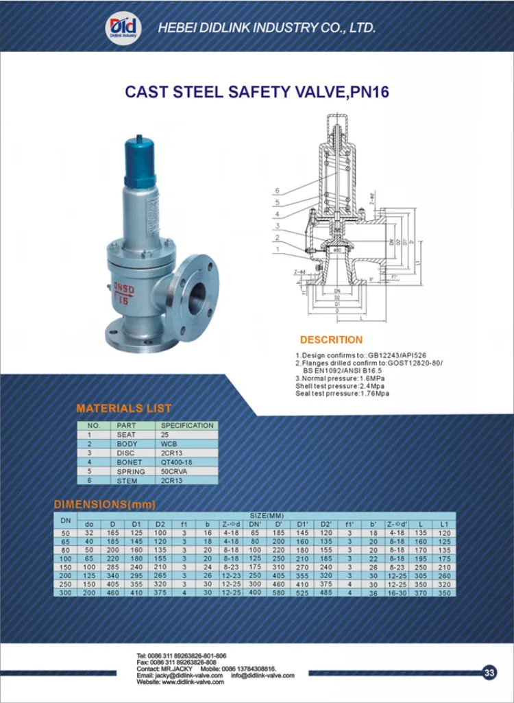
Material: Body- CF8M; Valve Seat- CF8M Métal Seat, PTFE Soft Seat available Orifice Size: fc"(15mm), 3/4M(20mm), l"(25mm), l1/4,’(32mm)I ltë”(40mm), ...
The Safety valves from ATOS are designed to guarantee protection for application on various devices, especially those that monitor spool position. They are also recommended for hydraulic ...
Fluidyne manufactured Safety Valves and Safety Relief Valves, Thermal Relief Valves, Boiler Safety Valves, Dead weight Safety and Relief Valves, Pilot operated Safety Relief Valve conform to API, ASME and IBR codes. Fluidyne carried out an extensive market research to design and manufacture durable and effective Safety Valves and Safety Relief Valves that are highly suitable for most chemical, petrochemical, oil, pharmaceutical, fertilizer, power and engineering industries and more. These industrial safety relief valves, flanged safety relief valves, dead weight relief valves, sanitary safety relief valves are high reliability and are approved by factory inspectors, inspectors under Indian Boiler Regulation (IBR), B.V., Lloyds and Chief Controller of Explosives. FLUIDYNE safety and relief valves are in used in above industries for over 35 years. Fluidyne Safety Valves and Safety Relief Valves are Full Lift, "Pop" action type, Full Nozzle or half nozzle having Screwed Butt/Socket weld or Flanged connections. Various Models are available as per requirements of customers. Sizes Range : ¼”(6 NB) to 12” (300 NB). All API standard Orifice sizes are available. Both Angle and Straight (in-line) Patterns are available. Inverted-Bottom spring mounted types available for mounting inside mobile pressure vessels. Connection offered are Screwed, Sanitary or Socket Weld / Butt Weld ends and Flanged ends to 150#, 300#, 600#, 900#, 1500# and 2500# rating. Flanged connections are offered with FF, R/F and RTJ ends to ANSI B16.5, BS, DIN,. Safety Valves and Safety Relief Valves are manufactured from castings and by fabrication from bar stock and all special trims provided as per customer requirements. Fluidyne manufactured Safety Valves and Safety Relief Valves, Thermal Relief Valves, Boiler Safety Valves, Dead weight Safety and Relief Valves, Pilot operated Safety Relief Valve conform to API 520, API 526, API RP 527, ASME SEC VIII DIV I and IBR codes Set pressure and hydro tests as per specification or standard are carried and provided. FLUIDYNE manufactures following types of Safety Valves and Safety Relief Valves :-
These Safety and Relief Valves are Standard models manufactured to API 520, API 526, API RP 527, ASME SEC VIII DIV I and IBR codes having full lift and high capacity and fitted as original equipments on boilers, reactors, pressure vessels and reactors.
Fluidyne range of small bore safety valves, industrial safety relief valves, flanged safety relief valves, industrial safety valves, flanged safety valves offer superior performance and maximum functionality. They are available in Screwed, Socket weld, Sanitary, Conflat and Flanged Construction type or flanged-inlet, Screwed-outlet connection type. Their simplicity in construction makes them pretty cost effective and easy to use.
Fluidyne Boiler Full Lift Full Flow Safety Relief Valve is a high performance valve designed and developed for steam and water service. It can also be used for most other applications like gases and vapors, saturated steam, superheated steam. Fluidyne Safety Relief Valve is designed for steam service. The valves are designed as per API 520, API 526 and meets the requirements of ASME Sec VIII-Division I. Fluidyne Boiler Safety Valves are offered with IBR Certification in Form III-C. The valves have a full nozzle or half nozzle and guided at the guide of the valve body, increasing the eficiency of the valve assembly. Specially designed disc holder ensures full lift within 5% to 10% overpressure or increase of pressure above the set pressure value. Blow down of a maximum of 5% to 10% is achieved in this design. Lapping of valve seat to optical flatness ensures leak tightness at seat. Full lift of valve disc ensures that the certified flow of the safety valve is discharged. Spring made of chrome vanadium steel is precisely selected and assembled so that the valve operates precisely and a good leak tightness is achieved at high temperatures with great repeatability.
Fluidyne Deadweight Safety valve consists of a valve seat where the pressure in the boiler or pressure vessel when it exceeds the normal working pressure lifts the valve seat with its weight. The excess pressure fluid therefore escapes through the pipe to the atmosphere, until the pressure reaches its normal value. It is the simplest type of safety valve; it is suitable for stationary boilers and pressure vessels only, because it cannot withstand the jerks and vibration of mobile boilers or pressure vessels. Another disadvantage of this valve is the heavy weight required to balance the pressure. Hence, it is not suitable for high pressure boilers.
FLUIDYNE Backpressure Safety Relief or Surplus or Diaphragm Assisted Safety Relief Valve is single seated, diaphragm controlled and spring regulated valve where the pressure of the system being relieved, acting upon the diaphragm provides a sensitive control of the valve opening in accordance with the regulating spring setting. The application or ideal for installations where a direct spring loaded type is too insensitive to pressure or flow changes. The Fluidyne Backpressure Relief Valve Protects systems from overpressure and Monitors pump outputs. Fluidyne Backpressure Relief Valve is most suitable for water, air, gas, steam, oil or chemical services.
Designed for installation on pressurised vessels and storage tanks, FLUIDYNE PIPE AWAY Pressure Relief Valve is designed to protect the vessel or tank from excessive internal pressure.
In the closed position the spring-loaded pallet and diaphragm assembly is held tightly against a seal to prevent the loss of vapour to atmosphere. As the internal pressure in the tank increases, due to product filling and vapour development, the pressure in tank increases and reaching set pressure of the unit, the diaphragm will open and discharge the air, gas or steam to the atmosphere. The opening set-point is selectable from a range between +50 mbar and +1000 mbar (other settings available on request), and the valve will close when the tank returns to a safe pressure.
Several features are inherent in the valve design to ensure a smooth, positive and effective operation. The body is self-draining and drip rings prevent condensate from settling on seating surfaces. A diaphragm and seal manufactured from Teflon reduce the possibility of ice formation and sticky residues hindering the valve from opening, while the pallet assembly moves freely on guideposts. Set pressure can be adjusted by adjusting spring settings.
The integrity of the seal is tested for leakage in accordance with API Standards. The size of the valve shall be calculated in accordance with API Standard, ASME or IBR codes


 8613371530291