
downhole safety valve animation free sample

Our downhole safety valves provide your testing operations with fail-safe sustained control downhole in the event of an emergency or to facilitate test procedures.

GEM-Valve system enables remediation without relinquishing control of subsurface safety shut-in equipment via wireless surface control of the valve, allowing reliable and regulatory compliant production of oil and gas wells.
Installed as a temporary safety valve solution, the system eliminates production deferral while workover intervention planning and sourcing activities take place. Installed as a permanent solution, it eliminates significant workover repair and recompletion costs, which might not be justifiable for old producing wells in mature fields.

This invention relates to surface controlled subsurface safety valves used in the oil and gas industry and particularly including a mechanism for temporarily locking the valves open and for remedial cycling of the valves.
It is common practice to complete oil and gas producing wells with systems including a subsurface safety valve controlled from the well surface to shut off fluid flow in the well tubing string. Generally such a valve is controlled in response to control fluid pressure conducted to the valve from a remote location at the well surface via a small diameter conduit permitting the well to be selectively shut in as well conditions require. However, the present invention is not limited to use with safety valves that respond only to fluid pressure signals. The surface controller is typically equipped to respond to emergency conditions such as fire, broken flow lines, oil spills, etc. Frequently it is necessary to conduct well servicing operations through a subsurface safety valve. When a safety valve malfunctions, it may be necessary to install a second safety valve. In any event, it may be desirable to either permanently or temporarily lock the safety valve open. For example, if the well servicing operation requires extending a wireline tool string through the subsurface safety valve, it is preferable to use a lock open system which is not dependent upon control fluid pressure from the well surface. When operations are being carried out through an open subsurface safety valve such as pressure and temperature testing, it can be extremely expensive and time-consuming for a valve to accidentally close on the supporting wireline causing damage to the wireline and sensing apparatus supported therefrom. Additional well servicing procedures are required to retrieve the damaged equipment. Subsurface safety valves including both a permanent and a temporary lock open mechanism are shown in the following U.S. Pat. Nos. 3,786,865; 3,882,935; 4,344,602; 4,356,867; and 4,449,587. The present invention particularly relates to a subsurface safety valve of the type shown in U.S. Pat. Nos. 3,786,865 and 4,449,587 employing a temporary lockout arrangement for the flapper type of valve closure included in the subsurface safety valves. The previously listed patents are incorporated by reference for all purposes in this application. Copending U.S. patent application Ser. No. 06/658,275 filed on Oct. 5, 1984 now U.S. Pat. No. 4,624,315 is directed towards solving some of the same problems as the present invention.
The present invention relates primarily to tubing retrievable flapper type safety valves having a housing connectable with a well tubing string and a bore therethrough for communicating well fluid flow with the tubing string, a flapper valve mounted in the housing for movement between a first open position and a second closed position, and an operator tube in the housing to shift the flapper valve between its second position and its first position. The operator tube normally moves in response to a control signal from the well surface, but a shifting tool can releasably engage the operator tube for movement independent of the control signal. A lockout sleeve may be mounted in the housing in tandem with the operator tube for movement between a first position engaging and holding the flapper valve open and a second position of disengagement from the flapper valve. A shifting tool is also provided having selective locating keys and latch dogs for releasably coupling with the operator tube and the lockout sleeve, respectively. An alternative embodiment of the present invention can be used with any type of surface controlled subsurface safety valve to cycle the valve closure mechanism if it is stuck or the control signal is inoperative.
It is a principal object of the present invention to provide a subsurface safety valve for use in oil and gas wells including a lockout sleeve for temporarily holding or locking open the safety valve during well servicing operations.
It is another object of the invention to provide a subsurface safety valve having an operator tube and a lockout sleeve with a shifting tool latching the operator tube and sleeve together during movement of the sleeve to a position in which the sleeve holds the valve closure mechanism of the subsurface safety valve open.
It is another object of the invention to provide a subsurface safety valve having a lockout sleeve which has a smooth, uniform inside diameter to minimize the possibility of other well tools accidentially shifting the lockout sleeve.
It is another object of the invention to provide a subsurface safety valve including a temporary lockout sleeve wherein the shifting tool does not engage the inside diameter of the temporary lockout sleeve to move the sleeve.
It is another object of the invention to provide a subsurface safety valve including an operator tube which may be operated by an alternative shifting tool to check the proper functioning and full travel of the operator tube of the safety valve.
Still another object of the invention is to provide a subsurface safety valve including a modified operator tube and an alternative shifting tool which may be used to move the operator tube of the valve to free the operator tube or valve closure means when jammed by sand or other well debris.
FIG. 1 is a schematic view in section and elevation of a typical well completion including a tubing retrievable subsurface safety valve with a flapper type valve closure means.
FIGS. 2A, 2B, 2C, and 2D taken together form a longitudinal view, in section and elevation with portions broken away, of a subsurface safety valve and lockout sleeve incorporating the present invention showing the safety valve in its open position.
FIGS. 5A, 5B, and 5C taken together form a longitudinal view in section and elevation showing the safety valve of FIGS. 2A-D with the valve closure means open, the lockout sleeve of the safety valve in its inoperative position, and the shifting tool of FIG. 3 engaged therewith.
FIGS. 6A, 6B, and 6C taken together form a view similar to FIGS. 5A, 5B, and 5C showing the shifting tool and the safety valve after shifting the lockout sleeve to hold open the valve closure means.
FIGS. 7A, 7B, and 7C taken together form a view similar to FIGS. 6A-C showing the shifting tool released from the operator tube in the safety valve after shifting the lockout sleeve to hold open the valve closure means.
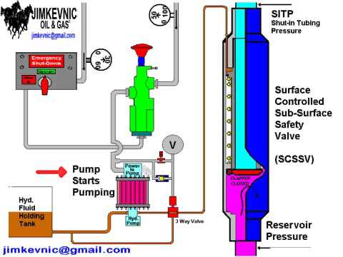
Referring to FIG. 1, well completion 20 includes casing string 28 extending from the well surface to a hydrocarbon producing formation (not shown). Tubing string 21 is concentrically disposed within casing 28 and extends from wellhead 23 through production packer 22 which seals between tubing string 21 and casing 28. Packer 22 directs formation fluids such as oil, gas, water, and the like into tubing string 21 from perforations (not shown) in casing 28 which admit formation fluids into the well bore. Flow control valves 24a and 24b at the well surface control fluid flow from tubing string 21. Wellhead cap 27 is provided on wellhead 23 to permit servicing well 20 via tubing string 21 by wireline techniques which include the installation and removal of various flow control devices such as valves from within tubing string 21. Other well servicing operations which may be carried out through tubing string 21 are bottom hole temperature and pressure surveys.
Surface controlled subsurface safety valve 30 embodying the features of the invention is installed in well 20 as a part of tubing string 21 to control fluid flow to the well surface via tubing string 21 from a downhole location. Safety valve 30 is operated by control fluid conducted from hydraulic manifold 25 at the well surface via control line conduit 26 which directs the control fluid signal to safety valve 30. Hydraulic manifold 25 generally includes pumps, a fluid reservoir, accumulators, and control valves for the purpose of providing control fluid pressure signals for holding valve 30 open or allowing valve 30 to close when desired. Manifold 25 also includes apparatus which functions in response to temperature, surface line leaks, and other emergency conditions under which well 20 should be shut in.
Safety valve 30 includes flapper type valve closure means 31 mounted by hinge 34 for swinging between a closed position schematically represented in FIG. 1 and an open position which permits fluid flow in tubing string 21. When a predetermined pressure signal is applied to safety valve 30 through control line 26 from manifold 25, valve closure means 31 is maintained in its first or open position. When the control pressure signal is released, valve 30 is allowed to move to its second or closed position. In accordance with the invention, lockout sleeve 50 is provided in valve 30 for movement between a first position which holds valve closure means 31 open and a second position in which valve closure means 31 is free to open or close. With flapper 31 restrained open by lockout sleeve 50, various well servicing operations may be conducted without fear of inadvertent closure of valve 30 which can be damaging to the servicing equipment.
Details of the construction of the preferred form of valve 30 and lockout sleeve 50 are shown in FIGS. 2A-D. Shifting tool 70 for operating lockout sleeve 50 illustrated in FIGS. 3A-B will also be described in detail. Subsurface safety valve 30 has housing means 60 formed by a top sub 61a, a bottom sub 61b, and interconnected housing subassemblies 62, 63, 64, 65, and 66 which are suitably interconnected by threaded joints as illustrated. Housing means 60 can be generally described as a long thick walled cylinder with longitudinal bore 67 extending therethrough. The top and bottom subs 61a and 61b may be internally or externally threaded to provide means on opposite ends of housing means 60 for connection with tubing string 21 as represented in FIG. 1. Top sub 61a includes locking grooves 68 machined on its inside diameter. Locking grooves 68 provide means for installing a secondary or retrievable safety valve (not shown) within longitudinal bore 67 if safety valve 30 should become inoperative. The secondary valve may be designed to operate in response to the same control signal as safety valve 30 or may be designed to respond directly to changing well conditions.
Housing subassembly 62 has threaded connection 29 to allow attaching control line 26 to safety valve 30. Control fluid pressure signals are communicated from the well surface via control line 26, threaded connection 29, passageway 81, and opening 82 to longitudinal bore 67. Cylinder 83 is positioned within longitudinal bore 67 adjacent to opening 82. During normal operation of safety valve 30, control fluid pressure signals are directed to operator tube 40 via annular passageway 84 formed between the inside diameter of housing subassembly 62 and the outside diameter of cylinder 83.
Permanent lockout sleeve 80 is slidably disposed within longitudinal bore 67. Permanent lockout sleeve 80 is sized to fit concentrically within cylinder 83. During normal operation of safety valve 30, knockout plug 85 holds permanent lockout sleeve 80 in its inactive position shown in FIG. 2A. If safety valve 30 should become inoperative, profile 86 on the inside diameter of permanent lockout sleeve 80 can be engaged by a suitable shifting tool (not shown) to force sleeve 80 into abutting contact with operator tube 40 and to open safety valve 30. Movement of sleeve 80 causes knockout plug 85 to shear, allowing communication of control fluid pressure signals therethrough. Snap ring 87 is carried by housing subassembly 62 within longitudinal bore 67 to lock sleeve 80 in place after it has moved. Matching teeth 88 are carried on the outside diameter of sleeve 80 and the inside diameter of snap ring 87. The use of locking recesses 68, permanent locking sleeve 80, and associated components to install a secondary safety valve within longitudinal bore 67 is well known in the art.
Operator tube 40 is slidably disposed within longitudinal bore 67 to shift valve closure means 31 from its second, closed position to its first, open position as shown in FIG. 2C. For ease of manufacture and assembly, operator tube 40 is constructed from two generally hollow, cylindrical subassemblies designated 40a and 40b. Subassemblies 40a and 40b are joined together by threaded connection 41. Piston seal means 42 is carried on the exterior of operator tube 40 to form a sliding fluid barrier with the inside diameter of housing subassembly 63 adjacent thereto. Seal means 43 is carried by cylinder 83 to form a fluid barrier with the exterior of operator tube 40. Stationary seal means 43, movable piston seal means 42, and the exterior of operator tube 40 therebetween define in part variable volume control fluid chamber 48. Control fluid pressure from annular passageway 84 is received within chamber 48 to act upon piston seal means 42 and to longitudinally slide operator tube 40 towards valve closure means 31 in response thereto. Biasing means or spring 44 is carried on the exterior of operator tube 40 between shoulder 64a on the inside diameter of housing subassembly 64 and shoulder 45 on the exterior of operator tube 40. Biasing means 44 applies a force to shift operator tube 40 longitudinally opposite from control fluid pressure in chamber 48. When control fluid pressure in chamber 48 is decreased below a preselected value, spring 44 moves operator tube 40 longitudinally upward to allow valve closure means 31 to return to its closed position. Spring 35 coiled around hinge 34 also assists in moving flapper 31 to its closed position.
A second lockout sleeve designated 50 is slidably disposed in housing means 60 in tandem with operator tube 40. In comparison to first lockout sleeve 80, second sleeve 50 can be classified as a temporary lockout device. Lockout sleeve 50 has a first position shown in FIG. 8 which holds valve closure means 31 in its first position and a second position shown in FIG. 2D which does not restrict movement of valve closure means 31 between its first and second positions. As shown in FIGS. 2D and 8, lockout sleeve 50 has a relatively smooth, uniform inside diameter. Therefore, it is difficult for a wireline tool to accidentally engage lockout sleeve 50 and shift it to an undesired position. The smooth, uniform inside diameter of lockout sleeve 50 is an important feature of the present invention.
A plurality of selective keys 76 are disposed within windows 77 extending through housing subsection 72a. Leaf springs 78 are carried on the inside diameter of subsection 72a adjacent to selective keys 76. Springs 78 are designed to project keys 76 radially outward through windows 77. Core means 71 has reduced diameter portion 91 which allows keys 76 to be compressed radially inward by restrictions in either tubing string 21 or safety valve 30. Shear pin 75 is used to hold reduced diameter portion 91 radially adjacent to keys 76 during insertion of tool 70. A plurality of bosses 92 are provided on reduced diameter portion 91 adjacent to each key 76. Bosses 92 and the interior of keys 76 are designed to allow inward compression of keys 76 when shear pin 75 is installed.
Keys 76 have an exterior profile which matches profile 46 of operator tube 40. Engagement of keys 76 with profile 46 prevents further downward movement of shifting tool 70 relative to safety valve 30 due to square shoulders 93 and 94. Force can then be applied to core means 71 to shear pin 75 and slide core means 71 longitudinally relative to housing means 72. This longitudinal movement positions bosses 92 radially adjacent to and contacting a portion of their respective key 76 to lock keys 76 radially projected as shown in FIG. 5A.
Shifting tool 70 has a plurality of latching dogs 100 spaced longitudinally from selective keys 76. Latching dogs 100 are slidably disposed within second windows 101 of housing subsection 72c. A leaf spring 102 is provided to project each dog 100 radially outward. Inner core means section 71c has a reduced diameter portion 103 which allows dogs 100 to be compressed radially inward by restrictions in tubing string 21 including portions of safety valve 30. Dogs 100 are specifically sized to fit within recess 58 below lockout sleeve 50.
For purposes of describing the operation of this invention, it will be assumed that safety valve 30 is installed in a well completed as shown in FIG. 1. Control fluid pressure is communicated from manifold 25 via control line 26 to housing means 60 of safety valve 30. Using standard well servicing techniques and surface wireline equipment (not shown), shifting tool 70 is introduced into tubing string 21 via wellhead cap 27.
In FIGS. 5A, B, and C, safety valve 30 is shown in its first position with control fluid pressure in chamber 48 acting on operator tube 40 to hold flapper 31 open. A wireline tool string (not shown) would be attached to fishing neck 74 to manipulate shifting tool 70 within longitudinal bore 67. Selective keys 76 are engaged with profile 46 in operator tube 40 to prevent further downward movement of shifting tool 70 relative to safety valve 30. This engagement allows force to be applied to fishing neck 74 by the wireline tool string to shear pin 75 into two pieces 75a and b as shown in FIG. 5A. The force applied to fishing neck 74 causes inner core means 71 to slide longitudinally downward until fishing neck 74 rests on the top of housing means 72. This downward movement of core means 71 will position bosses 92 behind their respective keys 76 and enlarged outside diameter portion 104 behind dogs 100. Leaf spring 96 will force shear pin 95 into annular recess 97 which locks keys 76 and latching dogs 100 radially expanded.
With safety valve 30 and shifting tool 70 positioned as shown in FIGS. 5A, B, and C, the next step towards temporarily locking open safety valve 30 is to decrease control fluid pressure in chamber 48 below a preselected value. Since keys 76 are locked into profile 46 and latching dogs 100 locked outward into recess 58, operator tube 40 and lockout sleeve 50 must move in unison. Force can be applied to shifting tool 70 via the wireline attached to fishing neck 74 to assist spring 44 in shifting operator tube 40 to its second position and lockout sleeve 50 to its first position as shown in FIG. 6A, B, and C.
The final result of these operations is shown in FIG. 8. Lockout sleeve 50 is in its first position holding flapper 31 open. Operator tube 40 has been returned to its second position. Shifting tool 70 has been removed from longitudinal bore 67. As previously noted, the smooth uniform inside diameter of lockout sleeve 50 greatly reduces the possibility of wireline service tools accidentally shifting sleeve 50 and returning it to its second position. When the desired well maintenance has been completed, safety valve 30 can be returned to normal operation by simply applying control fluid pressure to chamber 48. This pressure causes operator tube 40 to move to its first position. During this movement, operator tube 40 abuts lockout sleeve 50 and returns sleeve 50 to its second position.
During the initial installation of tubing string 21 within casing 28, lockout sleeve 50 can be used to check the integrity of control line 26 and the proper functioning of safety valve 30. During installation, safety valve 30 is preferably attached to tubing string 21 with valve closure means 31 and lockout sleeve 50 both in their first position. Collet fingers 52, bosses 53 and groove 55 are designed to allow a substantial amount of control fluid pressure to be applied to chamber 48 before operator tube 40 can shift lockout sleeve 50 to its second position. By applying less than this amount of pressure to control line 26 from manifold 25, the integrity of control line 26 can be monitored. A drop in control line pressure or a decrease in control fluid level at manifold 25 indicates a possible leak in control line 26 which should be investigated before completing well 20. After tubing string 21 is properly disposed within casing 28, sufficient pressure can be applied to control line 26 to shift lockout sleeve 50 to its second position. Proper operation of safety valve 30 can be verified by monitoring the control line pressure and volume required for this shifting.
The previous description has been directed towards an operator tube which opens a flapper type valve closure means. U.S. Pat. No. 3,860,066 to Joseph L. Pearce et al demonstrates that operator tube 40 could be modified to open and close ball type and poppet type valve closure means in addition to flapper 31. Therefore, the present invention is not limited to flapper valves. Shifting tool 170 shown in FIGS. 9A and 9B may be used to cycle any type of valve closure means between its open and closed position as long as the valve operator tube has been modified for releasable engagement with tool 170. Generally, shifting tool 170 will be used to open the valve closure means. However, it could be used to move the operator tube to close the valve closure means if required.
Some components and features of shifting tool 170 are identical to those of shifting tool 70 and will be given the same numerical designation. The principal structural differences between shifting tool 170 and previously described shifting tool 70 are the replacement of fishing neck 74 by equalizing valve and packing assembly 180 and removal of core means subsections 71b and c and housing means subsections 72b and c. The principal operating differences are that equalizing valve and packing assembly 180 allows fluid pressure in tubing string 21 to be applied to operator tube 40 and latching dogs 100 are not provided to shift lockout sleeve 50.
Equalizing valve and packing assembly 180 as shown in FIG. 9A includes fishing neck 174 for attachment to a standard wireline tool string. Fishing neck 174 is connected by threads to poppet valve plunger 181 which is slidably disposed in valve housing 182. Ports 183 communicate fluid between the interior and exterior of valve housing 182. Valve seat 184 is disposed within valve housing 182 for engagement with valve plunger 181.
Packing carrier 185 is attached to valve housing 182 by threads 187. Packing or seal means 186 is carried on the exterior of packing carrier 185. The dimensions of seal means 186 are selected to form a fluid barrier with the inside diameter housing subsection 61a when shifting tool 170 is engaged with operator tube 40. A hollow, longitudinal spacer 188 is used to attach packing carrier 185 to core means section 71a by suitable threaded connections. Longitudinal flow passageway 189 extends through valve housing 182, packing carrier 185, and spacer 188. Port 190 communicates between the exterior of spacer 188 and longitudinal flow passageway 189.
During installation of shifting tool 170, plunger 181 is spaced longitudinally above valve seat 184 to allow fluid in tubing string 21 to bypass seal means 186. When keys 76 engage profile 46, plunger 181 is lowered to contact valve seat 184 to block fluid flow via longitudinal passageway 189. The length of spacer 188 is preferably selected so that seal means 186 form a fluid barrier with the inside diameter of housing subsection 61a immediately below locking recesses 68. Hydraulic fluid pressure can then be applied from the well surface via tubing string 21 to act on seal means 186. Since the effective piston area of seal means 186 is much larger than piston seal means 42 carried by operator tube 40, shifting tool 170 can apply considerably more force to operator tube 40 to open valve closure means 31. This feature may be particularly desirable for ball type valve closure means. Also, spacer 188 could be removed if operator tube 40 is modified to allow seal means 186 to form a fluid barrier therewith.
The previous description has also been directed towards a safety valve which is opened and closed in response to a hydraulic fluid control signal from the well surface. The present invention can be used with any type of safety valve control signal including electrically operated valves such as shown in U.S. Pat. No. 3,731,742 to Phillip S. Sizer et al or U.S. Pat. No. 4,002,202 to Louis B. Paulos et al. Another alternative embodiment of the present invention, shifting tool 270 shown in FIGS. 10A and B, allows both opening a safety valve and locking the valve open if desired without regard to the presence of the valve"s normal control signal. This embodiment is particularly important as a backup feature for safety valve control systems which use electrical, electronic, sound, electro-hydraulic, hydraulic pilot or similarly sophisticated control systems. During periods when the sophisticated control systems are being repaired, shifting tool 270 allows a safety valve having an operator tube with profile 46 and lockout sleeve 50 to be temporarily locked open without regard to the presence of the normal control signal. A direct acting safety valve would preferably be installed until repair of the control system had been completed. Therefore, the present invention is not limited to hydraulically controlled safety valves and may in fact provide sufficient reliability to make more complicated control systems commercially acceptable for downhole safety valves.
In the event of a serious control line leak, it may not be desirable to use permanent lockout sleeve 80 to shift valve closure means 31 to its first position because formation fluids can then escape via the control line leak. Shifting tool 270 allows valve closure means 31 to be locked open without the use of control fluid pressure and without disturbing permanent lockout sleeve 80. A direct acting safety valve or STORM CHOKE® safety valve which does not require hydraulic control fluid can then be installed within longitudinal flow passageway 67 to maintain well safety. Prior to the present invention, the only solution to a serious control line leak was to remove tubing string 21 from the well bore--a very expensive procedure.
Shifting tool 270 is identical with shifting tool 70 except that fishing neck 74 has been replaced by equalizing valve and packing assembly 180 of shifting tool 170. Shifting tool 270 can use fluid pressure in tubing string 21 to open valve closure means 31 as previously described for shifting tool 170. Shifting tool 270 can be manipulated by a wireline tool string attached to fishing neck 174 to shift lockout sleeve 50 to its first position as previously described for shifting tool 70.
The previous description is illustrative of only some of the embodiments of the invention. Those skilled in the art will readily see other variations for a shifting tool and subsurface safety valve utilizing the present invention. Changes and modifications may be made without departing from the scope of the invention which is defined by the claims.
The field of this invention is downhole safety valves and more particularly those where the flapper can be locked open by shifting and locking the flow tube when disengaged from the power spring.
SSSVs are normally closed valves that prevent blowouts if the surface safety equipment fails. Conditions can arise where the SSSV fails to function for a variety of reasons. One solution to this situation has been to lock open the SSSV and to gain access into the pressurized control system that is used to move the flow tube to push the flapper into an open position against the force of a closure spring that urges the valve into a closed position. Thereafter, a replacement valve is delivered, normally on wireline, and latched into place such that the newly formed access to the control system of the original valve is now straddled by the replacement valve. This allows the original control system to be used to operate the replacement valve.
There have been several variations of lock open devices in the past. U.S. Pat. No. 4,577,694 assigned to Baker Hughes teaches the use of a flapper lock open tool (FLO) which delivers a band of spring steel to expand when retaining sleeves on the FLO tool are retracted. The tool latches inside the SSSV and with the flow tube in the flapper-closed position the band is released. This design offered the advantages of the lockout device not being integral to the SSSV. Instead it was only introduced when needed through a wireline. Another advantage was that the release of the band did no damage to the SSSV or the FLO tool. The band expanded into a recessed area so as to allow full-bore through-tubing access. The flow tube did not have to be shifted so that no spring forces acting on the flow tube had to be overcome to actuate the FLO tool. Subsequently, when the SSSV was retrieved to the surface, the band was easily removed by hand without special tools. The FLO tool had safety features to prevent premature release or incorrect placement. The FLO tool did not require fluid communication with the control system, as its purpose was solely flapper lock out.
U.S. Pat. No. 4,579,889 assigned to Camco, now Schlumberger, required latching in the SSSV and stroking the flow tube down to the valve open position. The flow tube would then be outwardly indented in the valve open position so that the indentations would engage a downwardly oriented shoulder to prevent the flow tube from moving back to the valve closed position. This design had some of the advantages of the Baker Hughes FLO design and could accomplish the locking open with a single wireline trip. The disadvantages were that the flow tube was permanently damaged and that the flow tube had to be forced against a closure spring force before being dimpled to hold that position. This made disassembly of the SSSV with the flow tube under spring pressure a potentially dangerous proposition when the valve was later brought to the surface.
U.S. Pat. No. 5,564,675 assigned to Camco, now Schlumberger, also involved forcibly pushing the flow tube against the spring to get the flapper into the open position. In fact, the flow tube was over-stroked to push the actuator piston out of its bore in the pressurized control system, at which point the piston would have a portion splay out preventing its re-entry into the bore, thereby holding the flow tube in the flapper open position. This design had the safety issues of disassembly at the surface where the flow tube was under a considerable spring force. Additionally, fluid communication into the control system was not an option when locking open using this tool.
A safety valve has a lock open feature that is actuated by expanding or penetrating the flow tube to disconnect the link between the piston in the hydraulic control system and the flow tube. In normal operation, downward movement of the piston moves the flow tube against a power spring. When the flow tube is expanded, penetrated, or otherwise altered, the piston no longer acts on the flow tube and the flow tube can be simply pushed down and locked in position with the flapper wide open.
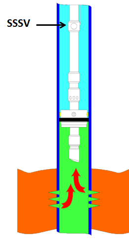
The specific portions of a SSSV are shown that are necessary for those skilled in the art to understand the invention. The other components are known and operate in a known manner and will not be discussed at length. During normal operations a flow tube 10 is secured to a piston 12 SO that pressure from the surface in annular chamber 14 drives the piston 12 and with it the flow tube 10 downwardly to force open a flapper 11 for the valve open position. Downward movement of the piston 12 takes with it ring 16 and, in turn, sleeve 18. Sleeve 18 bears on power spring 20. Power spring 20 goes from a relaxed position when the flow tube is in the up or valve closed position to a compressed position when the Valve is in the open position with the flow tube 10 pushed down. Spring 20 is shown fully compressed in FIG. 2b with the flow tube 10 fully pushed down. Ring 16 has a radial component 22, which bears on release ring 24. During normal operations, release ring 24 is mounted firmly in groove 26 on the outer surface of the flow tube 10. Accordingly, when radial component 22 is driven down it pushes down the release ring 24, which, in turn, pushes down the flow tube 10 because the release ring is secured in groove 26. With the release ring intact, the control system operates the SSSV in a known manner.
This application is a continuation of U.S. application Ser. No. 11/664,645 entitled “Downhole Safety Valve Apparatus and Method,” which claims the benefit of provisional application U.S. Ser. No. 60/522,500 filed Oct. 7, 2004 both of which are incorporated herein in their entireties by reference. BACKGROUND
The present invention generally relates to subsurface safety valves. More particularly, the present invention relates to an apparatus and method to install a replacement safety valve to a location where a previously installed safety valve is desired to be replaced. More particularly still, the present invention relates to communicating with a production zone through a bypass-conduit when a replacement safety valve is closed.
Subsurface safety valves are typically installed in strings of tubing deployed to subterranean wellbores to prevent the escape of fluids from one production zone to another. Absent safety valves, sudden increases in downhole pressure can lead to catastrophic blowouts of production and other fluids into the atmosphere. For this reason, drilling and production regulations throughout the world require safety valves be in place within strings of production tubing before certain operations can be performed.
One popular type of safety valve is known as a flapper valve. Flapper valves typically include a flow interruption device generally in the form of a circular or curved disc that engages a corresponding valve seat to isolate one or more zones in the subsurface well. The flapper disc is preferably constructed such that the flow through the flapper valve seat is as unrestricted as possible. Usually, flapper-type safety valves are located within the production tubing and isolate one or more production zones from the atmosphere or upper portions of the wellbore or production tubing. Optimally, flapper valves function as large clearance check valves, in that they allow substantially unrestricted flow therethrough when opened and completely seal off flow in one direction when closed. Particularly, production tubing safety valves can prevent fluids from production zones from flowing up the production tubing when closed but still allow for the flow of fluids and/or tools into the production zone from above.
Flapper valve disks are often energized with a biasing member (spring, hydraulic cylinder, etc.) such that in a condition with zero flow and with no actuating force applied, the valve remains closed. In this closed position, any build-up of pressure from the production zone below will thrust the flapper disc against the valve seat and act to strengthen any seal therebetween. During use, flapper valves are opened by various methods to allow the free flow and travel of production fluids and tools therethrough. Flapper valves may be kept open through hydraulic, electrical, or mechanical energy during the production process.
Examples of subsurface safety valves can be found in U.S. Provisional Patent Application Ser. No. 60/522,360 filed Sep. 20, 2004 by Jeffrey Bolding entitled “Downhole Safety Apparatus and Method;” U.S. Provisional Patent Application Ser. No. 60/522,498 filed Oct. 7, 2004 by David R. Smith and Jeffrey Bolding entitled “Downhole Safety Valve Apparatus and Method;” U.S. Provisional Patent Application Ser. No. 60/522,499 filed Oct. 7, 2004 by David R. Smith and Jeffrey Bolding entitled “Downhole Safety Valve Interface Apparatus and Method;” all hereby incorporated herein by reference. Furthermore, applicant incorporates by reference U.S. Non-Provisional application Ser. No. 10/708,338 Filed Feb. 25, 2004, titled “Method and Apparatus to Complete a Well Having Tubing Inserted Through a Valve” and U.S. Provisional Application Ser. No. 60/319,972 Filed Feb. 25, 2003 titled “Method and Apparatus to Complete a Well Having Tubing Inserted Through a Valve.”
Over time, a replacement subsurface safety valve may be desired. An existing subsurface safety valve can become stuck or otherwise inoperable either through failure of various safety valve components or because of caked-up hydrocarbon deposits, for example. In these circumstances, sudden increases in production zone pressure can lead to dangerous surface blowouts if the safety valves are not repaired. Because the repair or replacement of a subsurface safety valve formerly required the removal of the string of production tubing from the wellbore, these operations were frequently prohibitively costly for marginal wells. An improved apparatus and method to repair or replace existing subsurface safety valves would be highly desirable to those in the petroleum production industry. SUMMARY
In one embodiment, a replacement safety valve to hydraulically isolate a lower zone below the replacement safety valve and an existing safety valve comprises a main body having a clearance passage through a longitudinal bore and an outer profile, the outer profile removably received within a landing profile of the existing safety valve, a flow interruption device located in the clearance passage pivotably operable between an open position and a closed hydraulically sealed position, and a bypass-conduit extending from a surface location through the replacement safety valve to the lower zone. The bypass-conduit may be wholly contained within a bore of a string of tubing carrying the existing safety valve.
In another embodiment, the bypass-conduit can be in communication with the surface location and the lower zone below the valve when the flow interruption device is in the closed hydraulically sealed position. The bypass-conduit can be in communication with the surface location and the lower zone below the valve when the flow interruption device is in the open position. The lower zone can be a production zone.
In yet another embodiment, the bypass-conduit passes through the existing safety valve en route to the lower zone. The main body can retain a second flow interruption device of the existing safety valve in an open position. The existing safety valve can include a first hydraulic conduit in communication with the replacement safety valve through a second hydraulic conduit therein. The existing safety valve can include a nipple profile.
In yet another embodiment, the replacement safety valve of claim can further comprise hydraulic seals hydraulically isolating the replacement safety valve from the existing safety valve. The bypass-conduit can extend through the main body of the replacement safety valve. The bypass-conduit can be a hydraulic fluid passage, a continuous string of tubing, or a hydraulic capillary tube. The hydraulic capillary tube can be a fluid injection hydraulic capillary tube. The fluid can be a foam or a gas. The fluid can be selected from the group comprising surfactant, acid, miscellar solution, corrosion inhibitor, scale inhibitor, hydrate inhibitor, and paraffin inhibitor.
In another embodiment, the bypass-conduit can be a logging conduit, a gas lift conduit, an electrical conductor, or an optical fiber. The bypass-conduit can further comprise a check valve below the replacement safety valve. The bypass conduit can further comprise a check valve between the replacement safety valve and a wellhead. The bypass-conduit can further comprise a hydrostatic valve between the replacement safety valve and a wellhead. The bypass-conduit can further comprise a hydrostatic valve below the replacement safety valve.
In another embodiment, the replacement safety valve further comprises an operating conduit in communication with-a source of an energy, the energy actuating the flow interruption device between the open position and the closed hydraulically sealed position. The operating conduit can extend from the surface location through the first bore of the existing safety valve to the main body. The operating conduit can extend from the surface location to the replacement safety valve through a wall of the existing safety valve.
In yet another embodiment, a method to hydraulically isolate a zone below an existing safety valve from a string of tubing carrying the existing safety valve in communication with a surface location comprises deploying a replacement safety valve through the string of tubing to a location of the existing safety valve, engaging the replacement safety valve within a landing profile of the existing safety valve, extending a bypass-conduit from the surface location, through the replacement safety valve, to the zone below the existing safety valve, and communicating between the surface location and the zone below the existing safety valve through the bypass-conduit. The replacement safety valve may be movable between an open position and a closed position. The method may further comprising communicating between the surface location and the zone below the existing safety valve when the flow interruption device of the replacement safety valve is in a closed hydraulically sealed position. The zone below the existing safety valve can be a production zone.
In another embodiment, a method can further comprise the step of communicating between the surface location and the zone below the existing safety valve through the bypass-conduit when the flow interruption device of the replacement safety valve is in an open position. A method can further comprise the step of retaining a second flow interruption device of the existing safety valve in an open position with an outer profile of the replacement safety valve. The bypass-conduit can be a hydraulic fluid passage, a continuous tube, or a hydraulic capillary tube. The bypass-conduit can comprise a plurality of a jointed pipe section deployed from the surface location. A method can further comprise the step of including a check valve in the bypass-conduit above the replacement safety valve or below the replacement safety valve.
In another embodiment, a method can further comprise the step of injecting a foam or a fluid to the zone below the existing safety valve through the bypass-conduit. The fluid can be selected from the group consisting of corrosion inhibitor, scale inhibitor, hydrate inhibitor, paraffin inhibitor, surfactant, acid, and miscellar solution. The bypass-conduit can be a logging conduit. The logging conduit can be greater than about one and a half inches in diameter. A method can include a bypass-conduit which can be a gas lift conduit, an electrical conductor, or an optical fiber.
In yet another embodiment, the method can further comprise the step of operating the flow interruption device between the closed hydraulically sealed position and an open position with an operating conduit. The method can further comprise the step of extending the operating conduit from the surface location to the replacement valve through the string of tubing. The method can further comprise the step of communicating hydraulic pressure through the operating conduit, through a first passage in the existing safety valve to a second passage in the replacement safety valve. BRIEF DESCRIPTION OF THE DRAWINGS
FIG. 1 is schematic representation of a replacement safety valve assembly installed in an existing safety valve in accordance with an embodiment of the present invention.
Referring initially to FIG. 1, a schematic representation of a replacement subsurface safety valve assembly 100 is shown engaged within an existing subsurface safety valve 102. Existing safety valve 102 includes a generally tubular valve body 104, a flapper 106, a landing profile 108, and a clearance bore 110. Likewise, replacement valve assembly 100 includes a main body 112, an engagement profile 114, a flapper 116, and a clearance bore 118.
With a replacement safety valve desired to be located within an existing safety valve 102, replacement valve assembly 100 is disposed downhole through the string of tubing or borehole where preexisting safety valve 102 resides. Once replacement valve 100 reaches existing safety valve 102, replacement valve 100 is actuated through clearance bore 110 until engagement profile 114 of replacement valve 100 engages and locks within landing profile 108 of existing safety valve 102. Landing and engagement profiles 108, 114 are shown schematically in FIG. 1 but any scheme for mounting a tubular or a valve downhole known to one of ordinary skill in the art may be used.
For example, to lock into place replacement subsurface safety valve assembly 100 within landing profile 108 of existing safety valve 102, engagement profile 114 can be constructed with a collapsible profile, a latching profile, or as an interferencefit profile. In an interference-fit scheme (as shown schematically in FIG. 1), the outer diameter of engagement profile 114 is slightly larger than the diameter of the clearance bore 110 but slightly smaller than a minimum diameter of landing profile 108 of existing safety valve 102. Using this scheme, replacement valve 100 is engaged within clearance bore 110 until engagement profile 114 abuts valve body 104. Once so engaged, replacement valve 100 can be impact loaded until engagement profile 114 travels through clearance bore 110 and engages within landing profile 108. Alternatively, engagement profile 114 can be constructed to be retractable or extendable via wireline or hydraulic capillary such that the full dimension of engagement profile 114 is not reached until it is in position within landing profile 108.
Once installed, replacement valve body 112 opposes any biasing force remaining to retain flapper 106 of existing safety valve 102 out of the way within recess 120. Hydraulic seals 122, 124, and 126 isolate fluids flowing from production zones below valves 100, 102 through clearance bores 118, 110 from coming into contact with, and eroding components (106, 120) of existing safety valve 102 and the outer profile of replacement valve 100. Otherwise, paraffin and other deposits might clog the space defined between valve bodies 112 and 104 and could prevent subsequent repair or removal operations of either replacement valve 100 or existing safety valve 102.
In operation, fluids will flow from downhole zone 130, through clearance bore 118 of replacement valve 100, and through upper end of clearance bore 110 of existing safety valve 102 to upper zone 132. Typically, downhole zone 130 will be a production zone and upper zone 132 will be in communication with a surface station. Flapper 116 of replacement valve 100 pivots around axis 134 between an open position (shown) and a closed position (shown by dashed lines in FIG. 1). A valve seat 136 acts as a stop and seals a surface of flapper disc 116 to prevent hydraulic communication from lower zone 130 to upper zone 132 when flapper 116 is closed. With flapper 116 closed, increases in pressure in lower zone 130 act upon the bottom of and thrust flapper 116 against seat 136 with increased pressure to enhance any hydraulic seal therebetween. Typically, a torsional spring (not shown) acts about axis 134 to bias flapper disc 116 against seat 136 if not held open by some other means. Various schemes can be and have been employed to retain flapper 116 in an open position when passage from lower zone 130 to upper zone 132 is desired (or vice versa), including using a slidable operating mandrel or a hydraulic actuator housed within valve body 112. Regardless of how activated from open to closed position, flapper 116 acts to prevent communication from lower zone 130 to upper zone 132 when closed.
Additionally, replacement valve 100 can optionally be configured to have flapper 116 or any other component operated from the surface. An operating conduit (not shown) can optionally be deployed from a surface unit, through tubing and existing safety valve 102 to replacement valve 100 to operate flapper 116 from closed position to open position (or vice versa). Furthermore, referring again to FIG. 1, an existing operating conduit 140 emplaced with existing safety valve 102 can be used to operate flapper 116 of replacement valve 100. Specifically, operating conduit 140 extends from a surface location to existing safety valve 102 to operate flapper disc 106. While operating conduit 140 is shown schematically as a hydraulic conduit, it should be understood by one of ordinary skill in the art that any operating scheme including, electrical, mechanical, pneumatic, and fiber optic systems can be employed. A passage 142 connects operating conduit 140 to inner bore 110 of existing safety valve 102 to allow operating conduit 140 to communicate with replacement valve 100 through a corresponding passage 144. A pressure accumulator 146 is housed within main body 112 of replacement valve 100 and acts to store and convert pressure from operating conduit 140 into mechanical energy to displace flapper 116 between open and closed positions. Hydraulic seals 124, 126 ensure that any pressure in operating conduit 140 is maintained through passages 142, 144 and accumulator 146 with little or negligible loss. To prevent operating conduit 140 from communicating with bore 110 of existing safety valve 102 before replacement valve 100 is present, a rupture disc (not shown) can be placed within passage 142. Rupture disc can be configured to rupture at a pressure that is outside the normal operating range of existing safety valve 102. To install replacement valve 100, an operator increases pressure in operating conduit 140 to “blowout” rupture disc in passage 142 and then can install replacement valve 100. Once rupture disc is ruptured, operating conduit 140 can be used as normal to operate flapper 116 of replacement valve 100.
It is often desirable to communicate with lower zone 130 when flapper valve 116 is closed. For instance, there are circumstances where pressures within producing zones are such as to not allow the opening of flapper 116 but the injection of chemical, foam, gas, and other material to lower zone 130 is either beneficial or necessary. To accommodate such situations, a bypass-conduit 150 can be incorporated in replacement valve 100 such that communication between upper zone 132 and lower zone 130 can occur irrespective of the position of flapper 116. The upper zone 132 tan be a surface location. Bypass-conduit 150 includes an upper segment 152, a lower segment 154, and a passage 156 through replacement valve body 112 of replacement valve 100. Bypass-conduit 150 can be of any form known to one of ordinary skill in the art, but can be a single continuous hydraulic tube, a string of threaded tubing sections, an electrical conduit, a fiber-optic conduit, a gas lift conduit, or, depending of the size of replacement valve 100, a logging conduit. Typically, bypass-conduit 150 will most often be constructed as hydraulic capillary tubing allowing the injection of a chemical stimulant, surfactant, inhibitor, solvent, and foam from a surface location to lower zone 130.
Furthermore, if bypass-conduit 150 is constructed to allow the injection of fluid to lower zone 132 from above, a check valve 155 may be included to prevent increases in downhole pressure from blowing out past replacement valve 100 through bypass-conduit 150 to the surface. The term capillary tube is used to describe any small diameter tube and is not limited to a tube that holds liquid by capillary action nor is there any requirement for surface tension to elevate or depress the liquid in the tube. The term hydraulic and hydraulically are used to describe water or any other fluid and are not limited to a liquid or by liquid means, but can be a gas or any mixture thereof.

The PSV (Pressurizer Safety Valve) popping test carried out practically in the early phase of a refueling outage has a little possibility of triggering a test-induced LOCA due to a PSV not fully closed or stuck open. According to a KSNP (Korea Standard Nuclear Power Plant) low power and shutdown PSA (Probabilistic Safety Assessment), the failure of a HPSI (High Pressure Safety Injection) following a PSV stuck open was identified as a dominant accident sequence with a significant contribution to low power and shutdown risks. In this study, we aim to investigate the consequences of the NPP for the various accident sequences following the PSV stuck open as an initiating event through the thermal-hydraulic system code calculations. Also, we search the accident mitigation method for the sequence of HPSI failure, then, the applicability of the method is verified by the simulations using T/H system code.
The paper presents the results of the independent analysis of the operational event which took place on 07.11.2003 at Unit 1 of Rostov NPP. The event started with switching off the electrical generator of the turbine due to a short cut at the local switching substation. The turbine isolating valves closed to prevent damage of the turbine. The condenser dump valves (BRU-K) and the atmospheric dump valves (BRU-A) opened to release the vapour generated in the steam generators. After the pressure decrease in the steam generators BRU-K and BRU-A closed but one valve stuck opened. The emergency core cooling system was activated automatically. The main circulation pump of the loop corresponding to the steam generator with the stuck BRU-A was tripped. The stuck valve was closed by the operational stuff manually. No safety limits were violated. The analysis of the event was carried out using ATHLET code. A reasonable agreement was achieved between the calculated and measured values. (author)
In PWR steam generator tube rupture (SGTR) faults, a direct pathway for the release of radioactive fission products can exist if there is a coincident stuck-open safety relief valve (SORV) or if the safety relief valve is cycled. In addition to the release of fission products from the bulk steam generator water by moisture carryover, there exists the possibility that some primary coolant may be released without having first mixed with the bulk water - a process called primary coolant bypassing. The MB-2 Phase II test program was designed specifically to identify the processes for droplet carryover during SGTR faults and to provide data of sufficient accuracy for use in developing physical models and computer codes to describe activity release. The test program consisted of sixteen separate tests designed to cover a range of steady-state and transient fault conditions. These included a full SGTR/SORV transient simulation, two SGTR overfill tests, ten steady-state SGTR tests at water levels ranging from very low levels in the bundle up to those when the dryer was flooded, and three moisture carryover tests without SGTR. In these tests the influence of break location and the effect of bypassing the dryer were also studied. In a final test the behavior with respect to aerosol particles in a dry steam generator, appropriate to a severe accident fault, was investigated
Highlights: ► We modelled the ASTEC input file for accident scenario (SBO) and focused analyses on the behaviour of core degradation. ► We assumed opening and stuck-open of pressurizer relief valve during performance of SBO scenario. ► ASTEC v1.3.2 has been used as a reference code for the comparison study with the new version of ASTEC code. - Abstract: The objective of this paper is to present the results obtained from performing the calculations with ASTEC computer code for the Source Term evaluation for specific severe accident transient. The calculations have been performed with the new version of ASTEC. The ASTEC V2 code version is released by the French IRSN (Institut de Radioprotection at de surete nucleaire) and Gesellschaft für Anlagen-und Reaktorsicherheit (GRS), Germany. This investigation has been performed in the framework of the SARNET2 project (under the Euratom 7th framework program) by Institute for Nuclear Research and Nuclear Energy – Bulgarian Academy of Science (INRNE-BAS).
A safety injection event happened by opening of the Main Steam Safety Valve at Kori unit 1 on April 16, 2005. The safety valves were opened at the lower system pressure than the valve opening set point due to rapid system pressure drop by opening of the Power Operated Relief Valve installed at the upstream of the Main Steam System. But the opening mechanism of safety valve at the lower set point pressure was not explained exactly. So, it needs to be understood about the safety valve opening mechanism to prevent a recurrence of this kind of event at a similar system of Nuclear Power Plant. This study is aimed to suggest the hydrodynamic mechanism for the safety valve opening at the lower set point pressure and the possibility of the recurrence at similar system conditions through document reviewing for the related previous studies and Kori unit 1 event
Full Text Available BACKGROUND Implantation of prosthetic cardiac valves to treat haemodynamically significant valvular diseases has become common; however, it is associated with complications. Thus, this study was intended to evaluate the indications for implantation of prosthetic valve and complications after its implantation and prognosis after treatment of one of its complication, i.e. stuck valve. MATERIALS AND METHODS This was a single-centered study wherein 50 patients who came to the emergency department with stuck valve were assessed. The 2D echocardiography was performed in all patients. Thrombolysis was done and the gradients were reassessed. Further response to treatment and development of complications before and after treatment were observed. RESULTS Of total patients, 60% were females. Mean age group was 30-40 yrs. Most of them were asymptomatic for 6 years and there was lack of compliance in 90% of patients. Most common indication for valve replacement was mitral stenosis (60% followed by mitral regurgitation (20%, aortic regurgitation and aortic stenosis (10% and combined mitral and tricuspid regurgitation (10%. Commonest valve was St. Jude (90%. Pannus was observed in 10% patients and thrombus was observed in 50% patients. Most patients had gradients 45/20 mmHg across mitral valve. In about 90% patients, gradients decreased after thrombolysis (12/5 mmHg. The complications after thrombolysis were hemiparesis (4%, death before thrombolysis (6% and death after thrombolysis (4%. CONCLUSION Considering these results, it can be concluded that prosthetic valves are seldom associated with some complications. Further, thrombolysis can be effective in patients with prosthetic valve thrombosis.
Purpose: To enable the detection of the closing of a safety valve when the internal pressure in a BWR type reactor is a value which will close the safety valve, by inputting signals from a pressure detecting device mounted directly at a reactor vessel and a safety valve discharge pressure detecting device to an AND logic circuit. Constitution: A safety valve monitor is formed of a pressure switch mounted at a reactor pressure vessel, a pressure switch mounted at the exhaust pipe of the escape safety valve and a logic circuit and the lide. When the input pressure of the safety valve is raised so that the valve and the pressure switch mounted at the exhaust pipe are operated, an alarm is indicated, and the operation of the pressure switch mounted at a pressure vessel is eliminated. If the safety valve is not reclosed when the vessel pressure is decreased lower than the pressure at which it is to be reclosed after the safety valve is operated, an alarm is generated by the logic circuit since both the pressure switches are operated. (Sekiya, K.)
After the TMI event efforts were aimed towards improvements in the operational and administrative procedures related to the power operated relief valves (PORVs) in order to decrease the probability of a small-break loss-of-coolant accident (LOCA) caused by stuck-open power operated relief valve. This paper presents a frequency probabilistic analysis of a small break LOCA due to a stuck open PORV and safety valve to the Angra I nuclear power plant in operating conditions pre-TMI and post-TMI. (Author) [pt
... 46 Shipping 2 2010-10-01 2010-10-01 false Opening between boiler and safety valve (modifies PFT-44). 52.20-17 Section 52.20-17 Shipping COAST GUARD, DEPARTMENT OF HOMELAND SECURITY (CONTINUED) MARINE ENGINEERING POWER BOILERS Requirements for Firetube Boilers § 52.20-17 Opening between boiler and safety valve...
The blowdown of a spring loaded safety valve is defined as the difference between the pressure at which the valve opens and the pressure at which the valve fully closes under certain fluid flow conditions. Generally, the blowdown is expressed in terms of percentage of the opening pressure. An extensive series of tests carried out in the EPRI/PWR Utilities Valve Test Program has shown that the blowdown of safety valves can in general be strongly dependent upon the valve geometry and other parameters such as ring adjustments, spring stiffness, backpressure etc. In the present study, correlations have been developed using the EPRI safety valve test data to predict the expected blowdown as a function of adjustment ring settings for geometrically similar valves under steam discharge conditions. The correlation is validated against two different size Dresser valves
In performing the safety analyses for transients that result in a challenge to the reactor coolant system (RCS) pressure boundary, the general acceptance criterion is that the peak RCS pressure not exceed the American Society of Mechanical Engineers limit of 110% of the design pressure. Without crediting non-safety-grade pressure mitigating systems, protection from this limit is mainly provided by the primary and secondary code safety valves. In theory, the combination of relief capacity and setpoints for these valves is designed to provide this protection. Generally, banks of valves are set at varying setpoints staggered by 15- to 20-psid increments to minimize the number of valves that would open by an overpressure challenge. In practice, however, when these valves are removed and tested (typically during a refueling outage), setpoints are sometimes found to have drifted by >50 psid. This drift should be accounted for during the performance of the safety analysis. This paper describes analyses performed by Yankee Atomic Electric Company (YAEC) to account for setpoint drift in safety valves from testing. The results of these analyses are used to define safety valve operability or acceptance criteria
... gov/ency/article/007408.htm Aortic valve surgery - open To use the sharing features on this page, ... separates the heart and aorta. The aortic valve opens so blood can flow out. It then closes ...
In Korean 3 Loop plants a water loop seal pipe is installed containing condensed water upstream of a pressurizer safety valve to protect the valve disk from the hot steam envir


 8613371530291