
downhole safety valve animation brands

Our downhole safety valves provide your testing operations with fail-safe sustained control downhole in the event of an emergency or to facilitate test procedures.
Baker Hughes’s portfolio of subsurface safety valves deliver reliable performance when it matters the most, providing emergency closure in the event that well control is lost. We offer a full range of valves to suit applications ranging from shallow- to deep-set, and the valves are available in surface- and subsurface-controlled, tubing-retrievable, and wireline-retrievable options. All Baker Hughes valves undergo stringent prototype testing and conform to standards and specifications such as API and ISO, as well as requirements requested for your unique situation.
A downhole safety valve refers to a component on an oil and gas well, which acts as a failsafe to prevent the uncontrolled release of reservoir fluids in the event of a worst-case-scenario surface disaster. It is almost always installed as a vital component on the completion.
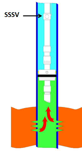
These valves are commonly uni-directional flapper valves which open downwards such that the flow of wellbore fluids tries to push it shut, while pressure from the surface pushes it open. This means that when closed, it will isolate the reservoir fluids from the surface.
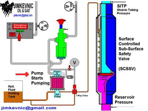
Most downhole safety valves are controlled hydraulically from the surface, meaning they are opened using a hydraulic connection linked directly to a well control panel. When hydraulic pressure is applied down a control line, the hydraulic pressure forces a sleeve within the valve to slide downwards. This movement compresses a large spring and pushes the flapper downwards to open the valve. When hydraulic pressure is removed, the spring pushes the sleeve back up and causes the flapper to shut. In this way, it is failsafe and will isolate the wellbore in the event of a loss of the wellhead. The full designation for a typical valve is "tubing retrievable, surface controlled, subsurface safety valve", abbreviated to TR-SCSSV.
The location of the downhole safety valve within the completion is a precisely determined parameter intended to optimise safety. There are arguments against it either being too high or too low in the well and so the final depth is a compromise of all factors. MMS regulations state that the valve must be placed no less than 30 m (100 ft) below the mudline.
The further down the well the DHSV is located, the greater the potential inventory of hydrocarbons above it when closed. This means that in the event of loss of containment at surface, there is more fluid to be spilled causing environmental damage, or in the worst case, more fuel for a fire. Therefore, placing the valve higher limits this hazard.
Another reason relates to the hydraulic control line. Hydraulic pressure is required to keep the valve open as part of the failsafe design. However, if the valve is too far down the well, then the weight of the hydraulic fluid alone may apply sufficient pressure to keep the valve open, even with the loss of surface pressurisation.
As part of the role of the DHSV to isolate the surface from wellbore fluids, it is necessary for the valve to be positioned away from the well where it could potentially come to harm. This implies that it must be placed subsurface in all circumstances, i.e. in offshore wells, not above the seabed. There is also the risk of cratering in the event of a catastrophic loss of the topside facility. The valve is specifically placed below the maximum depth where cratering is expected to be a risk.
If there is a risk of methane hydrate (clathrate) plugs forming as the pressure changes through the valve due to Joule–Thomson cooling, then this is a reason to keep it low, where the rock is warmer than an appropriately-calculated temperature.
Most downhole safety valves installed as part of the completion design are classed as "tubing retrievable". This means that they are installed as a component of the completion string and run in during completion. Retrieving the valve, should it malfunction, requires a workover. The full name for this most common type of downhole safety valve is a Tubing Retrievable Surface Controlled Sub-Surface Valve, shortened in completion diagrams to TRSCSSV.
If a tubing retrievable valve fails, rather than go to the expense of a workover, a "wireline retrievable" valve may be used instead. This type of valve can fit inside the production tubing and is deployed on wireline after the old valve has been straddled open.
The importance of DHSVs is undisputed. Graphic images of oil wells in Kuwait on fire after the First Gulf War after their wellheads were removed, demonstrate the perils of not using the components (at the time, they were deemed unnecessary because they were onshore wells). It is, however, not a direct legal requirement in many places. In the United Kingdom, no law mandates the use of DHSVs. However, the 1974 Health & Safety at Work Act requires that measures are taken to ensure that the uncontrolled release of wellbore fluids is prevented even in the worst case. The brilliance of the act is that it does not issue prescriptive guideline for how to achieve the goal of health and safety, but merely sets out the requirement that the goal be achieved. It is up to the oil companies to decide how to achieve it and DHSVs are an important component of that decision. As such, although not a legal requirement, it is company policy for many operators in the UKCS.
While the DHSV isolates the production tubing, a loss of integrity could allow wellbore fluid to bypass the valve and escape to surface through the annulus. For wells using gas lift, it may be a requirement to install a safety valve in the "A" annulus of the well to ensure that the surface is protected from a loss of annulus containment. However, these valves are not as common and they are not necessarily installed at the same position in the well, meaning it is possible that fluids could snake their way around the valves to surface.
Field-proven Weatherford safety valve technology guards against catastrophic loss of well control. The Optimax Ultra Deep-Set Safety Valve shuts in a well in the event of uncontrolled flow. This rod-piston, flapper-type valve has heavy-duty springs and metal-to-metal seals to enhance reliability for a fail-safe closure at pressures up to 10,000 psi (68 MPa). The Optimax ultra deep-set safety valve delivers V1-rated reliability to your operation. This valve can be set as deep as 12,000 ft (3,658 m) to provide fail-safe closure at pressures up to 10,000 psi (68 MPa).
Weatherford engineers every Optimax safety valve for durability and reliability. We combined the quality you expect with the functionality you need to shut in a well. Our Optimax portfolio of safety valves lead the industry in design simplicity and reliability.
The ultra deep-set safety valve overcomes the challenges of nitrogen-charged safety valves with a design that uses highly reliable, field-proven technology. With two rod pistons acting in opposite directions, the Optimax valve is tubing-pressure insensitive and does not rely on nitrogen-charged chambers, which can bleed off over time. Optimax valves require only low operating pressures, which reduce costs on subsea trees and umbilicals. Its simple design eliminates sleeves or plugs that can be inadvertently actuated.
Each valve is validated through a testing program that exceeds API 14A requirements. The result is high performance and reliability in deepwater applications in temperatures between 35°F and 350°F (2°C and 177°C).
The safety valve can be run with one or two control lines, for greater operational flexibility. The valve can be remotely exercised using pressure applied through the second control line to help shift the valve. For deep-set applications, the Optimax model WUDP-10 valve provides the option of using a wireline-retrievable insert safety valve that operates on the tubing-pressure insensitive system principle.
A safety valve is a valve that acts as the protector of your equipment. Safety valves can prevent damage to your pressure vessels and even prevent explosions at your facility when installed in pressure vessels.
A safety valve is a type of valve that automatically actuates when the pressure of the inlet side of the valve increases to a predetermined pressure, to open the valve disc and discharge the fluid. The safety valve system is designed to be a fail-safe so that a wellbore can be isolated in the event of any system failure or damage to the surface production-control facilities.
In most cases, it is mandatory to have a means of closure for all wells capable of natural flow to the surface. The installation of a subsurface safety valve (SSSV) will provide this emergency closure capability. Safety systems may be operated on a fail-safe principle from a control panel located on the surface that was custom-built by PHC.
The SCSSV is controlled by a ¼” stainless steel control line that is attached to the outside of the well tubing string and installed when the production tubing is installed. Depending on the wellhead pressure, it may be necessary to keep as much as 10,000 psi on the control line to keep the valve open. PHC control panels feature the proven Haskel pump line that generates the required hydraulic pressure for optimal valve control.

Baker Hughes has commercialized its Reconnect technology, the company announced at a news conference on 20 September at the SPE Annual Technical Conference and Exhibition in Florence, Italy. The system was developed by BJ Servicesas a technology to restore surface control to subsurface safety valves.
The system provides an alternative for re-establishing surface hydraulic control to surface-controlled subsurface safety valves (SCSSVs) that are inoperable due to compromised control lines or if the installation of a storm choke is undesirable, Mark Embrey, senior sales rep for Baker Hughes capillary services, explained at the news conference.
This technology is also a viable option for wells that were not completed with SCSSVs. It includes a wireline-retrievable safety valve, a through-tubing replacement control line that strings into the new valve assembly and a wellhead adapter. Installation requires a minimal crew and equipment suitable for almost any platform or wellsite, according to Baker Hughes.
SCSSVs are designed to stop flow in the event of a catastrophic failure. They are installed in the production tubing and are mandatory in most offshore wells and some land wells. Primary SCSSVs are held open by hydraulic pressure from a control line that runs through the annulus to the surface. If pressure in the control line is lost, such as during an emergency shutdown or if the line is cut, the valve will close and revert to its fail-safe closed position, stopping flow from the well.
Traditionally, a storm choke would be installed or a workover intervention would be performed to regain surface control. But the Reconnect system does not require a workover rig. Mr Embrey adds that the new system can be customized “to fit almost any wellhead and safety valve out there.”
In one GOM installation, a mature well developed a leak in the control line of its subsurface safety valve. Injecting sealants did not repair the leak. The operator considered installing a velocity valve, but the well was scheduled for a plug-and-abandonment operation for one zone and the perforation of a new zone. Adjusting and re-adjusting a velocity valve for the new zone was expected to be time-consuming and expensive because of the well’s remote location.
The operator installed the Reconnect system, which provided flexibility to vary the well’s production rate without the intervention required to pull the velocity valve and adjust the differential pressure settings. In addition, the operator could perform mandatory testing of the downhole safety valve without the added cost of a lift boat previously required due to the small platform’s limited crane capacity and deck space.

SSSV: Subsurface Safety Valve: a valve installed in the tubing down the well to prevent uncontrolled flow in case of an emergency through the tubing when actuated. These valves can be installed by wireline or as an integral part of the tubing. Subsurface Valves are usually divided into the following categories.
SCSSV: Surface-Controlled Subsurface Safety Valves: SSSV which is controlled from the surface and installed by wireline or as an integral part of the tubing.
SSCSV (storm choke): Subsurface-Controlled Subsurface Safety Valve: SSSV which is actuated by the flow characteristics of the well, and is wireline retrievable.
ASV: Annulus Safety Valve: a valve installed in the well to prevent uncontrolled flow in the casing-tubing annulus when actuated. It consists of an annular safety valve packer with a by-pass. The opening in the by-pass is controlled by a safety valve, which can be an integral part of the packer on a wireline retrievable valve.
The tubing safety valve is installed to provide a flow barrier in the production tubing string, between the tail pipe and the surface or mudline. Such a valve consists of 3 main items:
Safety valve should not be considered as an extra barrier in the tubing when the well is closed-in for a long period of time. Sealing is not optimal because of design space limitations. They should not be used to regularly shut-in the well.
The annulus safety valve (ASV) provides a flow barrier in the casing-tubing annulus. It consists of an annular safety valve packer with a by-pass. The opening of the by-pass is controlled by a safety valve, which can be an integral part of the packer or a wireline retrievable valve. It is a surface controlled, fail-safe closed device for annular flow.
In general, the ASV is installed in gas lifted wells where the annulus is filled with compressed gas and serves as a barrier. Because of gas lift valves, the tubing cannot be considered as a barrier between the reservoir and the surface. Although the gas lift valves are commonly equipped with check valves, they are not a valid barrier. The ASV is normally located at a shallow depth to reduce the volume of the gas stored in the annulus between the ASV and the wellhead.
The valve body and connections should be at least as strong as the tubing. It should provide leak resistance to internal and external pressures and be compatible with the fluids.
During the installation of the tubing string, it is necessary to keep the valve open. This can be done by inserting a retrievable lock-open tool in the valve, without or in combination with the control signal from surface.
Multiple zone completions, where wireline jobs are frequent on equipment installed beneath the safety valve. The larger bore of a TR-SSSV facilitates the operations, where a WR-SSSV normally has to be retrieved.
The wireline retrievable safety valve (WR SCSSV) is run on wireline. A lock mandrel is screwed on top of the WR SCSSV that enables using a landing nipple. This nipple must hold the valve/mandrel assembly against pressure differentials loads. The nipple has a polished bores to seal the path between WR SCSSV and landing nipple by seals fitted to the outside of the valve/mandrel assembly.
With hydraulically operated WR SCSSVs, the external seals have also the function of containing the control fluid that is to be transmitted to the valve actuator.
The landing nipple for an electrically operated valve has a connection for an electric control line and an inductive coupler to transmit the signal to the WR SCSSV.
Trough Flowline retrievable safety valves use specially constructed mandrels and landing nipples. They must have a stronger hold-open force than SCSSVs, because the Trough Flowline tools are circulated upwards in the tubing string, which tends to drag the valve"s flow tube up, causing the valve to close. To overcome this problem the actuator hold-open force should be higher than the sum of the normal hold open force and the drag forces that can be experienced. Trough Flowline retrievable SSSVs can be used for subsea completions where wireline operations are difficult.
Another application is to install a SSSV in tubing without a landing nipple. Such a system consists of a production packer with an integral safety valve. The assembly is positioned by the coiled tubing and the packer is set by pressure from the coiled tubing.
Subsurface controlled valves are normally open and are designed to close with an abnormal change in well condition. They detect the flow or well pressure and close when the set limit is reached. Basically there are three different concepts:
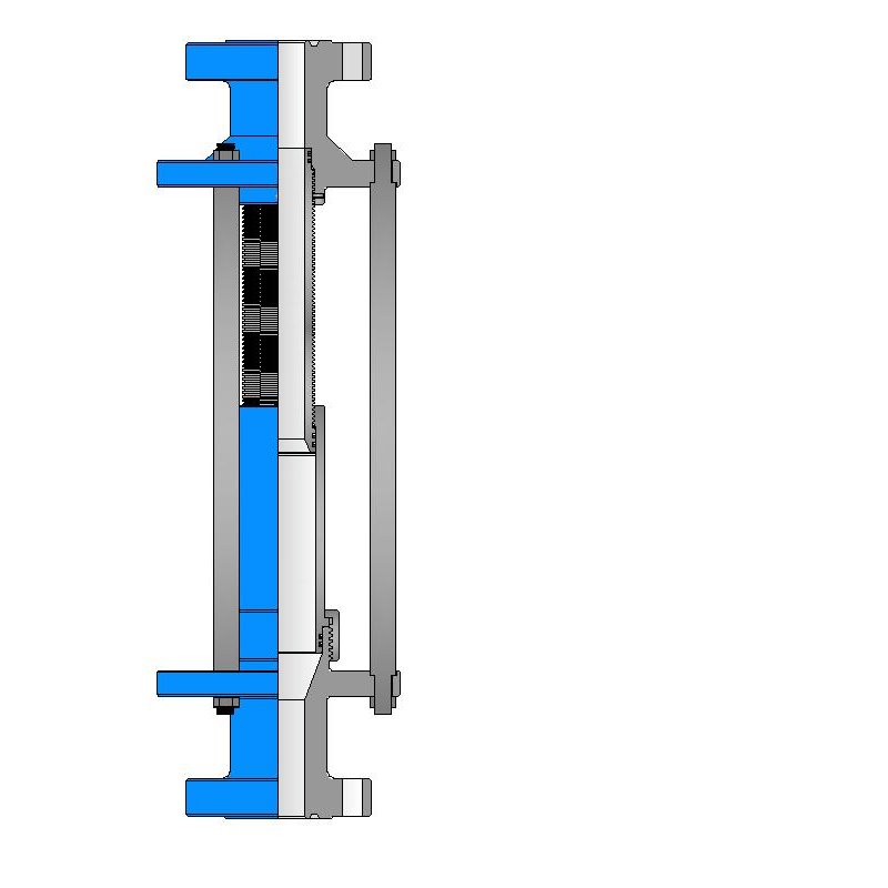
Surface controlled valves utilise valve elements that are normally closed. This fail-safe mode requires that the valve is to be opened by a hydraulic control-line pressure. Loss of this pressure will result in the closing of the valve by a spring. The hydraulic pressure is supplied from a surface control panel to the valve and acts on the actuator. Typical for hydraulic operated SCSSVs is the hydrostatic head pressure, generated by the vertical column of control fluid, which additionally acts on the valve actuator.
the surface control line pressure and the time for valve operation will give an indication whether the valve opening and closing performance is satisfactory;
TR-SCSSVs of which the hydraulic actuator is damaged can be put back into function by inserting a back-up valve (insert valve), which can be operated with the existing hydraulic control system;
Electrically operated SCSSVs have in common with hydraulic SCSSVs that the differential pressure over the closed valve must be equalised before the valve can be opened and a means to keep the valve open must be permanently available from surface for fail safe operation.
With electric valves that means is an electrical signal, either dc or ac. Loss of this signal will result in closing of the valve. The force to close is always provided by expanding steel springs, which are precompressed by either electric power or by the well pressure.
One type of mechanically operated SSSV is the Go-Devil valve from Otis. This safety valve is a normally open valve. It is designed to close by an impact force on the head of the valve, provided by a heavy ball that is dropped from a ball-dropper assembly at surface. The impact force will activate the spring based mechanical linkage, that moves the valve to the closed position.
The ball-dropper assembly is flange mounted on top of the Christmas tree. The pocket of the ball dropper retains the ball, sized to activate the Go-Devil SSSV by falling against flow and impacting the head of the valve. The ball dropper assembly retains the ball until the loss of the control signal activates the release mechanism.
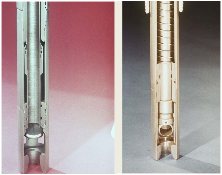
Three types of valve closure elements are commonly used for SSSV: the ball, the flapper and the poppet type. The flapper valve can further be divided in flat, contoured and curved flappers, while the poppet valve can be divided into closed body and sleeve type poppet valves. All types of closure elements pinch off the fluid stream by a pair of opposing surfaces rather than sliding surfaces. This principal method has the advantage that it can provide a good tight shut-off when the sealing surfaces are sound.
As noted the flapper valves may be flat, curved or contoured. The latter two were introduced to obtain a better OD/ID ratio, as they are shaped to fit when in the open position, more efficiently in the annular space of the valve housing.
The seat angle is the shape of the flapper sealing surfaces, which is an important parameter of the valve sealing performance. Traditional flapper valves have a seat angle of 45°, as the angled seat has the advantage that:
Due to the characteristics of the curved flapper design the seat angle may vary from 0° to 60° along the flapper circumference, thus requiring stringent alignment of the sealing faces. The contoured flapper design has an angled sealing surface over the full circumference of the flapper and thus has potential to provide good sealing. Field experience indicate that the flapper valve type is more reliable than the ball valve type.
When a SSSV is closed, a high differential pressure may be present across the valve closure element. Opening the valve under this condition will be difficult, if not impossible, because of the incapability of the relatively small valve mechanism to cope with the load working on the large diameter closure element. Insufficient equalising will introduce high loads that could deform critical valve parts. Also, erosive wash-out on the closure element by the sudden rush of well fluid through the partly opened valve can occur. Therefore, prior to opening a SSSV it is necessary to equalise the differential pressure.
The depth at which to set the subsurface safety valve depends upon a number of variables, such as hydrate and wax formation tendencies, deviation kick-off depth, scale precipitation, earthquake probabilities, etc. The OD of the safety valve may influence the casing/tubing string configuration and should be addressed at the conceptual design stage.
For tubing safety valves it is obvious that the deeper the valve is set (closer to the hydrocarbon source) the more protection it will give to the completion. However, the application of a deep-set tubing SSSV generates some unfavourable conditions, namely:
the higher temperature further downhole effects the reliability and the longevity of non-metal valve parts, for instance polymeric seals in hydraulic valves and electric/electronic parts in electric valves;
the hydrostatic head pressure generated by the hydraulic control-line column will generate excessive forces on the valve operating mechanism. Hence, designing and manufacturing of these valves becomes more complicated.
Furthermore, the required control pressure to operate a single control line valve (the majority of SSSVs) could become too high and more than the pressure rating of standard well completion equipment.
The approach for determining the required hydraulic control pressure at surface to hold a valve open depends on the type of valve, viz. the single control line valve, the dual control line valve and the valve with a pressure chamber.
Due to friction in the valve mechanism and the spring characteristic, there is a certain spread between the valve opening pressure (Pvo) and closing pressure (Pvc).
To ensure that the valve is completely open, a safety factor or pressure margin (Pm) is added to the surface control pressure. Hence, the available control pressure at surface to open the valve must be at least:
The dual control line valve or the pressure balanced valve uses a second control line from surface to balance the generated hydrostatic head pressure in the control line. The forces acting to operate this type of valve are as follows:
Due to friction in the valve mechanism and the spring characteristic, there is a certain spread between the valve opening pressure (Pvo) and closing pressure (Pvc).
When the valve is in the fully open position and the control and the balance line are both filled with fluid of the same fluid gradient, the following force equilibrium exists:
To insure that the valve is completely open, a safety factor or pressure margin (Pm) is added to the surface control pressure. Hence, the available control pressure at surface to open the valve must be at least:
The dome charged valve uses a pressure in an integral dome to (partly) balance the generated hydrostatic head pressure in the control line. The forces acting to operate this type of valve are as follows:
Due to friction in the valve mechanism and the spring characteristic, there is a certain spread between the valve opening pressure (Pvo) and closing pressure (Pvc).
To ensure that the valve is completely open, a safety factor or pressure margin (Pm) is added to the surface control pressure. Hence, the available control pressure at surface to open the valve must be at least:
The theoretical maximum setting depth of a single control line SSSV depends on the capacity of the valve closing spring to overcome the generated hydrostatic head pressure in the control line. For fail safety it is essential that the tubing pressure is not taken into account for the assistance of valve closing, even though single control line valves are assisted by this pressure. Hence, the governing factors for the maximum valve setting depth are:
* For fail safety, the worst case must be assumed, one in which the control line ruptures near the valve and annulus fluid will enter the control line. Therefore, for any completion the heaviest fluid gradient, either from the control fluid or from the annulus fluid, is used as the minimum control line fluid gradient.
Because the hydrostatic head pressure in the control line is counteracted, the setting depths of the dual control-line and the dome-charged valves are theoretically not limited.
Once a well commissioned to plant/ production facility then is set for a prolonged producing phase and in course of production well may face multiple completion string failures from any completion jewelry which can lead to suspend production or force to produce compromising well safety which is always unacceptable or operational risk.
The scale may cause serious well intervention problems during wireline jobs to run and seat plugs, downhole chokes, shifting SSD, running to latch GLV or opening Downhole safety valves etc etc. Scale deposits usually treated/ dissolved with scale dissolvers (a blend of converters and chelating agents) mixed with fresh water (if water base) or selecting appropriate fluid (Toluene & Xylene mixed with HSD and water in certain ratio) after lab tests usually. This operation is conducted via Coiled tubing in two to three stages with 42 to 72 hours of soaking times etc.
SCSSV (Surface Controlled Subsurface safety Valves) are downhole safety valves which give positive shut-off during any disaster at wellhead or well fittings. The safety valve will either be Tubing mounted called TRSCSSV or Wireline retrievable called WRSCSSV. Down hole safety valve is operated by applying hydraulic pressure from surface through a ¼” Control line passing thru tubing hanger via annulus to Safety valve. There are several issues can happen malfunctions to Safety valves such us flapper or flow tube stuck or valve sealing elements/ v-packings, static and dynamic seal wear outs etc.
WRSCSSV may be pulled out via slick line and any problem may be rectified whether its flow tube stuck issue or seals & packing etc. If such problems occur in any TRSCSSV then you may not go for any W/O operation to pull couple of stands and replace TRSCSSV however you still have some cost effect options to restore well safety.
The Oilenco version offers a simple ball and lock mechanism which precisely locates and grips the safety valve flow tube and in same way Baker one offered Permanent Lock Open Tool is compatible to PLOT baker all FVL, FVLE, FVLS, FVH, FVHE and deep set FVHD & FVLD model TRSCSSVs
After PLOT job a wireline retrievable safety valve assembled with appropriate lock mandrel + a spacer tube is run and straddled / seated into TRSCSSV upper locking groove using same existing control line and this is one of excellent solution to eliminate safety issue. Such type of safety valves are called Insert –Type WRSCSSV.
Very similar, when WRSCSSV (Wireline Retrievable Surface Controlled Subsurface Safety Valves) dislodge/ pop out again and again due to damage/ wear out or design fault of landing nipple locking key grooves upper, then upper slip assy may be a good choice/ application to to assemble Downhole Safety Valve with S&LM( Slip& LockMandrel) and secure WRSCSSV to avoid well to costly Workovers to restore well safety barrier.
PBR (Polished Bore Receptacles) are hooked above production packers in completion string where extreme movement is anticipated in high pressure and temperature wells. In course of production PBR leakages are also reported and in such caused to cure safety barrier retrievable Anchored Production Straddle (APS) assembly are best options.
In dual, straddled and multi zone completion wells SSD gate shifting is normal in well intervention jobs. Repeated SSD shifting up and down cause leakages from SSD gates due to O-ring worn outs or gate finger damages due to excessive jarring. SSD leakages caused pressurized annulus which is considered to be a safety barrier.
Designed to provide protection from well-control events, Superior surface-controlled subsurface safety valves are built and tested to the highest API standards. Our field-proven line will allow you to quickly close a well when needed, protecting assets and people. Available in sizes from 2-3/8” to 7”, our retrievable safety valves are designed for setting depths of up to 3,000 feet and pressures of up to 10,000 psi.

Abstract Surface Controlled Subsurface Safety Valves (SCSSV) is a critical completion accessory to maintain the Safe Operation Envelope (SOE) of the well and ensuring the production sustainability. In PCSB, it is a requirement that SCSSVs are tested on specific periods to ensure this safety device meet the acceptance requirement as per company guideline.
Short term solution such as reviewing the recommended hydraulic line opening pressure, downhole visual inspection, pressure activated sealant and caliper survey to confirm BP-6 Landing Nipple seal bore damage, Swellable Packer/O-ring (External) and re-dress using non-upgraded Elastomers (Internal) had been planned. Contingency for subsurface controlled SSV and replacement using new WRSCSSV had been put in place as long-term solution. This paper describes operator experience in managing the challenges in maintaining SCSSV operability, diagnostic and solution recommended to avoid production deferment due to this issue.


 8613371530291