
downhole safety valve animation pricelist
Our downhole safety valves provide your testing operations with fail-safe sustained control downhole in the event of an emergency or to facilitate test procedures.
Surface-controlled subsurface safety valves (SCSSVs) are critical components of well completions, preventing uncontrolled flow in the case of catastrophic damage to wellhead equipment. Fail-safe closure must be certain to ensure proper security of the well. However, this is not the only function in which it must be reliable—the valve must remain open to produce the well. Schlumberger surface controlled subsurface safety valves exceed all ISO 10432 and API Spec 14A requirements for pressure integrity, leakage acceptance criteria, and slam closure.
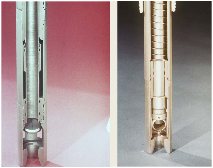
Through decades of innovation and experience, Schlumberger safety valve flapper systems are proven robust and reliable. The multizone dynamic seal technology for hydraulic actuation of subsurface safety valves is a further improvement in reliability performance when compared with traditional seal systems in the industry.
The multizone seal technology is currently available in the GeoGuard high-performance deepwater safety valves, which is validated to API Spec 14A V1 and V1-H.

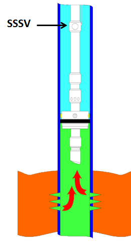
A downhole safety valve refers to a component on an oil and gas well, which acts as a failsafe to prevent the uncontrolled release of reservoir fluids in the event of a worst-case-scenario surface disaster. It is almost always installed as a vital component on the completion.
These valves are commonly uni-directional flapper valves which open downwards such that the flow of wellbore fluids tries to push it shut, while pressure from the surface pushes it open. This means that when closed, it will isolate the reservoir fluids from the surface.
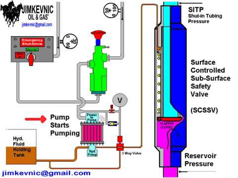
Most downhole safety valves are controlled hydraulically from the surface, meaning they are opened using a hydraulic connection linked directly to a well control panel. When hydraulic pressure is applied down a control line, the hydraulic pressure forces a sleeve within the valve to slide downwards. This movement compresses a large spring and pushes the flapper downwards to open the valve. When hydraulic pressure is removed, the spring pushes the sleeve back up and causes the flapper to shut. In this way, it is failsafe and will isolate the wellbore in the event of a loss of the wellhead. The full designation for a typical valve is "tubing retrievable, surface controlled, subsurface safety valve", abbreviated to TR-SCSSV.
The location of the downhole safety valve within the completion is a precisely determined parameter intended to optimise safety. There are arguments against it either being too high or too low in the well and so the final depth is a compromise of all factors. MMS regulations state that the valve must be placed no less than 30 m (100 ft) below the mudline.
The further down the well the DHSV is located, the greater the potential inventory of hydrocarbons above it when closed. This means that in the event of loss of containment at surface, there is more fluid to be spilled causing environmental damage, or in the worst case, more fuel for a fire. Therefore, placing the valve higher limits this hazard.
Another reason relates to the hydraulic control line. Hydraulic pressure is required to keep the valve open as part of the failsafe design. However, if the valve is too far down the well, then the weight of the hydraulic fluid alone may apply sufficient pressure to keep the valve open, even with the loss of surface pressurisation.
As part of the role of the DHSV to isolate the surface from wellbore fluids, it is necessary for the valve to be positioned away from the well where it could potentially come to harm. This implies that it must be placed subsurface in all circumstances, i.e. in offshore wells, not above the seabed. There is also the risk of cratering in the event of a catastrophic loss of the topside facility. The valve is specifically placed below the maximum depth where cratering is expected to be a risk.
If there is a risk of methane hydrate (clathrate) plugs forming as the pressure changes through the valve due to Joule–Thomson cooling, then this is a reason to keep it low, where the rock is warmer than an appropriately-calculated temperature.
Most downhole safety valves installed as part of the completion design are classed as "tubing retrievable". This means that they are installed as a component of the completion string and run in during completion. Retrieving the valve, should it malfunction, requires a workover. The full name for this most common type of downhole safety valve is a Tubing Retrievable Surface Controlled Sub-Surface Valve, shortened in completion diagrams to TRSCSSV.
If a tubing retrievable valve fails, rather than go to the expense of a workover, a "wireline retrievable" valve may be used instead. This type of valve can fit inside the production tubing and is deployed on wireline after the old valve has been straddled open.
The importance of DHSVs is undisputed. Graphic images of oil wells in Kuwait on fire after the First Gulf War after their wellheads were removed, demonstrate the perils of not using the components (at the time, they were deemed unnecessary because they were onshore wells). It is, however, not a direct legal requirement in many places. In the United Kingdom, no law mandates the use of DHSVs. However, the 1974 Health & Safety at Work Act requires that measures are taken to ensure that the uncontrolled release of wellbore fluids is prevented even in the worst case. The brilliance of the act is that it does not issue prescriptive guideline for how to achieve the goal of health and safety, but merely sets out the requirement that the goal be achieved. It is up to the oil companies to decide how to achieve it and DHSVs are an important component of that decision. As such, although not a legal requirement, it is company policy for many operators in the UKCS.
While the DHSV isolates the production tubing, a loss of integrity could allow wellbore fluid to bypass the valve and escape to surface through the annulus. For wells using gas lift, it may be a requirement to install a safety valve in the "A" annulus of the well to ensure that the surface is protected from a loss of annulus containment. However, these valves are not as common and they are not necessarily installed at the same position in the well, meaning it is possible that fluids could snake their way around the valves to surface.

Safety valves are designed to automatically shut in the flow of a well in the event surface controls fail or surface equipment becomes damaged. They are classified according to the location from which they are controlled – surface or subsurface. In this article, subsurface safety valve types, operating systems, working principle, setting depth, and selection process are presented.
It is advisable, and in most cases mandatory, to have a secondary means of closure for all wells capable of natural flow to the surface. The installation on of a sub-surface safety valve (SSSV) will provide this emergency closure capability.
Operating systems may be either remotely operated on a fail-safe principle from surface (SCSSV) actuated from a control panel located on surface, or will be a subsurface controlled (SSCSV), designed to close automatically when a predetermined flow condition occurs in the well (actuated by the pressure differential/flow velocity across the valve).
In case of SCSSV, a 1/4″ inch stainless steel control line is attached to the outside of the tubing string and installed when the tubing is installed. Depending on the wellhead pressure, it may be necessary to keep as much as 4000 to 5000 psi on the control line to keep the valve open.
The differential type subsurface controlled subsurface safety valve senses pressure drop across a flow bean. There are several variations of the differential type SSCSV. Although they employ different sealing devices, such as a flapper or ball, they all are controlled with a flow bean and spring tension.
As shown in the following video, when hydraulic pressure is applied down a control line, the hydraulic pressure forces a sleeve within the valve to slide downwards. This movement compresses a large spring and pushes the flapper (in case of flapper type SCSSV) or the ball (in case of ball type SCSSV) downwards to open the valve. When hydraulic pressure is removed, the spring pushes the sleeve back up and causes the flapper (or the ball) to shut. In this way, it is failsafe and will isolate the wellbore in the event of a loss of the wellhead.
The location of the downhole safety valve within the completion is a precisely determined parameter intended to optimise safety. There are arguments against it either being too high or too low in the well and so the final depth is a compromise of all factors. MMS regulations state that the valve must be placed no less than 100′ below the mudline.
AVK double orifice, triple acting air valves are designed for automatic rapid pipe filling and pipe draining as well as for automatic discharge of accumulated air during normal working conditions. The unique ‘Aerokinetic’ design, where air rushing out of the system cannot force the float upwards and close it prematurely, makes sure that the valve closes only after all air has left the system and water has entered the chamber. All ductile iron components are coated with GSK approved fusion bonded epoxy to ensure high durability. All other components are made by either a WRAS approved polymer material or stainless steel to minimize corrosion risk. All seals are made of WRAS approved EPDM rubber featuring an excellent compression set and ability to regain its original shape.


 8613371530291