
downhole safety valve animation quotation
A surface-controlled subsurface safety valve (SCSSSV) system without external wires or hydraulic lines needed for the valve"s operation is now available to the petroleum industry. Any of the current down-hole safety valves, such as Hydril, Otis, Camco or Baker, can be fitted to the valve operator. This is a totally fail-safe valve system, which can be overridden manually at the operator"s choice to accomplish a number of different modes. The valve"s operator is acoustically controlled by the operator"s predetermined settings at the surface. The predetermined settings at the surface. The receiver, translator, and valve actuator are packaged and placed in a special mandrel that is packaged and placed in a special mandrel that is run as a part of the tubing string. The hydraulic valve operator is mounted on a length of production tubing between the mandrel and valve. The full-flow valve is at the bottom of the down-hole string. Any length of production tubing may be run below the valve. Hookwall hangers can be run in as may be needed.
With the movement of the oil industry into the more or less hostile environment of offshore operations, it was apparent immediately to the oil operators that an automatic "fail-safe" valve was needed for the producing oil or gas "flow string".
A valve was produced that would respond to changes in flow rate either above or below levels preset into the valve. The first valve to be so adapted and so employed was the differential pressure, spring-loaded valve. Abnormal increases in the flow rate across the valve caused it to close. This valve was very simple in construction, could be set in the production string and removed by means of a production string and removed by means of a wireline. The differential pressure valve and its "sister" valve, the ambient pressure valve, which closed automatically if the rate of flow or resultant pressure across the valve dropped below a preset valve. These safety valves became known to the oil industry as "storm chokes", but actually the term "storm choke" is a registered patent term; therefore, such valves should only be referred to as down-hole production string safety valves. production string safety valves.
A safety valve is a valve that acts as the protector of your equipment. Safety valves can prevent damage to your pressure vessels and even prevent explosions at your facility when installed in pressure vessels.
A safety valve is a type of valve that automatically actuates when the pressure of the inlet side of the valve increases to a predetermined pressure, to open the valve disc and discharge the fluid. The safety valve system is designed to be a fail-safe so that a wellbore can be isolated in the event of any system failure or damage to the surface production-control facilities.
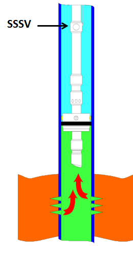
In most cases, it is mandatory to have a means of closure for all wells capable of natural flow to the surface. The installation of a subsurface safety valve (SSSV) will provide this emergency closure capability. Safety systems may be operated on a fail-safe principle from a control panel located on the surface that was custom-built by PHC.
The SCSSV is controlled by a ¼” stainless steel control line that is attached to the outside of the well tubing string and installed when the production tubing is installed. Depending on the wellhead pressure, it may be necessary to keep as much as 10,000 psi on the control line to keep the valve open. PHC control panels feature the proven Haskel pump line that generates the required hydraulic pressure for optimal valve control.
PLUSCO 621-622 Safety Valve Sealant will improve the overall performance of the safety valve by insuring a continuous seal for extended operation. It eliminates line leaks, improves the hydraulic pump performance, maintains tighter seals and valve seating and reduces fluid friction in the system. The benefits of sealing, lubricity and operations efficiency are provided by PLUSCO 621-622 Safety Valve Sealant. Safety Valve Sealant will insure a continuous flow of the gas well without interruption or unnecessary shutdown.PLUSCO 621-622 Safety Valve Sealant is available in two grades depending on the severity of the leak in the system.
PLUSCO 621-622 Safety Valve Sealant is a high tech safety valve additive specifically designed for sealing hydraulic controlled surface or subsurface safety valves.PLUSCO 621 is designed for slow weeping leaks while PLUSCO 622 is for heavy pinhole type leaks.

The WellStar® tubing-retrievable safety valve is a general production, hydraulically operated, downhole TRSV. The rugged hydraulic actuator of the WellStar safety valve provides durability and isolates the internal workings from well fluids through its unique construction. The metal-to-metal (MTM) sealing integrity in the body joints and closure mechanism places it in a premium valve category while featuring an economical price. Proven through years of installations, the simple, compact design enhances the valve’s overall reliability and provides for trouble-free operation.

Intermediate spool inserted below the Chrtistmas tree; spool provides a profile for landing the control line hanger and hydraulic penetration to allow control on WCS Safety Valve
Weatherford’s Brian Marr, Scott Carline and Scott Deyoung discuss how the Renaissance WDCL system enabled the retrofitting of a new control line inside existing tubing to reestablish connection with a surface-controlled subsurface safety valve (SCSSV). The installation, which was performed without a workover rig, improved production at a significant cost savings.
The well, an offshore oil producer in the Middle East, was required by law to include a SCSSV. Like all downhole safety valves, SCSSVs act as a failsafe to prevent the uncontrolled release of reservoir fluids in the event that surface wellhead integrity is lost. These valves are popular well control options in the industry due to their ease of operation, which consists of hydraulic control from the surface. Hydraulic pressure is applied down a control line connecting the valve to surface. During normal well operation, the continuous application of this hydraulic pressure keeps the valve open. When hydraulic pressure is removed during a wellhead integrity event, the valve is forced shut, thus acting as a failsafe to isolate the wellbore.
However, SCSSVs are prone to malfunction, which is commonly caused by piston failures, leaks within the valve body or some type of control line failure such as crushing, leaking or blocking by an obstruction. Such a control line failure occurred in the offshore Middle East well, which forced the valve closed and shut in production.
The conventional remediation method calls for bringing in a workover rig to pull the tubing, replace the blocked control line and then redeploy downhole. While this option is relatively cost-effective and easy to implement in an onshore well, the logistics, cost and complexity of performing a workover offshore make this a time-consuming and expensive operation. Even a relatively simple workover of an offshore well in the Middle East might cost upwards of US$6 million, according to estimates from the operator. Weatherford collaborated with the operator to develop an alternative process— an intervention that would restore functionality to the SCSSV by retrofitting a new control line and inserting a new valve within the existing well architecture. The operator required the intervention to be performed without killing the well, pulling the tubing or incurring the time delays and costs that commonly come with a major workover.
Upon review of the well parameters and intervention requirements, the operator decided to deploy Weatherford’s Renaissance WDCL system, a wirelineretreivable subsurface safety valve that allows both the control line and the safety valve to be replaced in a straightforward retrofit procedure. The system has a modified packing mandrel and wet connection, and a valve-and-lock assembly that can be installed in an existing tubing-mounted safety valve or safety-valve landing nipple. A capillary line is then run from the surface inside the tubing and connected to the valve to provide control. The retrofit process for this offshore well was performed from a jackup rig, and began by modifying the wellhead to provide the correct profile for the capillary hanger and gain access for the new capillary control line. A wireline crew set plugs in the well to keep the well isolated, after which the tree was pulled and a spool piece containing a hanger profile was installed. The tree was then reinstalled and after the wellhead was pressure tested, the wireline crew went back in and pulled the plugs.
Another trip downhole was conducted to lock open the existing tubing-retrievable safety valve, after which a new subsurface safety valve was deployed and landed inside the previous valve. Once the new valve was set, the capillary control line was run down the center of the tubing to a pod on the valve.
A weighted and centralized stinger placed at the end of the capillary string was used to join the capillary to a mating connection on the valve. This was a wet-connect assembly, which was hydraulically locked in place by applying pressure to the capillary string. The wet connect contains unique design features, including the ability to be mated and unmated should the capillary need to be removed, and dual-back check valves that prevent backflow through the capillary line as an additional safety feature.
The top end of the capillary was then landed into the new spool piece below the tree through a specially designed, 4-in. control-line hanger. A Type-H profile was provided above the hanger to allow for the installation of a backpressure valve, which would be required to secure the well during future wellhead maintenance.
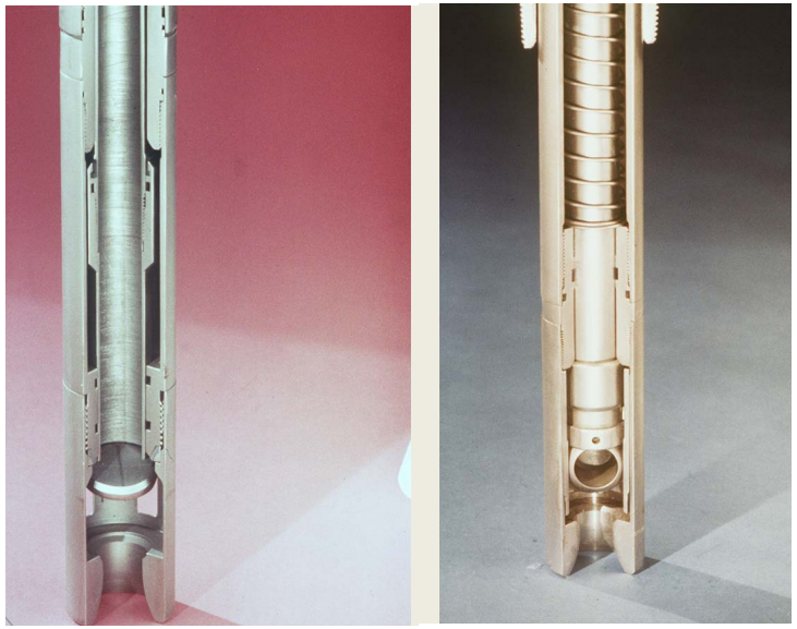
Picture of the WDCL Subsurface Safety Valve in the closed position (flapper shown in gold), the blue highlights the flow path of hydraulic fluid to function the valve.
The Renaissance WDCL was installed without incident, allowing the operator to bring the well back to full production quickly, while adhering to offshore safety regulations in the region.
A new spool piece was placed below the lower master valve on the wellhead. The spool piece was custom-built with a profile to lock the control line hanger in place, and polished bores for the seals.
United States Patent 11 1 A Young AMBIENT PRESSURE RESPONSlVE SAFETY VALVE l PM i /3a on 3,814,181 1451 June 4, 1974 Primary Examiner-James A, Leppink Attorney, Agent, or Firm-David L. Moseley; Stewart F. Moore; William R. Sherman [57] ABSTRACT A safety valve apparatus for wells producing well fluid by formation pressure and including a valve mechanism that is normally maintained in the open or flowing position by an urging means and is closed responsive to a predetermined differential pressure developed between flowing pressure, within the valve apparatus and ambient pressure, externally of the valve apparatus. A predetermined differential pressure develops a force overcoming the bias of the urging means and moves the valve mechanism to the closed position thereof. The valve apparatus is provided with means for modifying the effective size of the inlet orifice of the valve mechanism responsive to a predetermined decrease in ambient pressure from a normal operating range, thereby developing the predetermined pressure differential for achieving automatic closure of the safety valve apparatus.
AMBIENT PRESSURE RESPONSIVE SAFETY VALVE FIELD OF THE INVENTION This invention relates generally to safety valve apparatus for downhole environment in wells having a formation pressure for producing well fluid, and more specifically concerns the provision of a safety valve apparatus adapted for positive closure of a safety valve mechanism in the event ambient pressure at the level of the safety valve should decrease below a predetermined minimum.
BACKGROUND OF THE INVENTION In the early stages of development of the petroleum industry it was typically the practice to tap a pressurized source or reservoir of petroleum products by drilling and to allow any gas pressure that might be contained therein to dissipate to a controllable level or to a level at which the petroleum products might be recovered by pumping. The gas during this particular period was substantially unusable and wasgenerally wasted. Where oil was blown fromthe well along with the escaping gas, it was the practice to collect the oil in surface ditches constructed about the well site. As the petroleum industry rapidly developed, it was discovered that the pressurized gas within production formations could be efficiently utilized to produce other petroleum products contained therein and the gas itself could be efficiently marketed in its natural state or in other physical states, such as the liquid state, for example. Various developments have been made to ensure against the loss of gas pressure within petroleum reservoirs, but most of the early developments were related to surface control valves and the like that might be manipulated manually or mechanically for flow control purposes.
It is obviously necessary to provide subsurface production flow control mechanisms that may be controllable automatically or selectively as desired to prevent well blow-outs even though surface flow control equipment may be damaged or rendered inoperative. Subsurface production flow control apparatus of this nature may be capable of preventing explosion and fires that otherwise might occur in the event of damage or malfunction that surface flow control systems. Moreover, subsurface flow control safety equipment may effectively prevent the pollution of the surface environment tha might otherwise occur if an offshore well is allowed to blow wild. Since subsurface safety valve mechanisms may effectively present a great majority of well blow-outs and since pollution control is so extremely important from the standpoint of conservation, it is obvious that subsurface safety mechanisms are necessary to efficient functioning of the petroleum industry.
THE PRIOR ART Various well safety systems have been developed, involving both surface and subsurface safety equipment, that may be actuated to a safe position in response to the development of an adverse well condition, to stop the flow of production fluid, until the production equipment may be made safe for further operation. Actuation of safety valves may be automatically controlled by pilot mechanisms, responsive to remote sensing, or in the alternative, safety valves may be actuated to the safe position by a force developed responsive to an adverse well condition. Offshore wells may include production equipment provided with a safe-mode that may allow production of the well or may cause the well to shut in the event of storms or other hazardous conditions that might otherwise adversely affect production operations.
Surface and subsurface safety valve equipment may be developed that effectively achieves shut-in of surface or subsurface production flow control equipment to terminate the flow of production fluid in the event excessive well pressures should develop and in the event the flow control equipment may be subjected to excessive flow of production fluid. For the most part, presently available downhole safety valve equipment is solely velocity sensitive and remains open to allow the flow of production fluid during periods of normal or low velocity flow. Such valves are typically actuated by forces developed during high velocity flow to move the valve structure to the closed position and stop the flow of production fluid.
Where a well is being produced and a failure occurs in the production system of the well, it is desirable that the well shut in automatically. One typical device for serving this purpose is a so-called velocity sensitive valve that includes a spring operator piston which is sealingly slidable within a housing and carries a flow restriction, typically referred to as a flow bean, through which the flowing well fl-uid passes. The pressure drop across the restriction of the flow bean acts on an area defined generally by the piston seal diameter and the bore diameter of the flow restriction to produce an upward resultant force that is related to the flow rate or velocity. When the flow rate increases to a value sufficient to compress the spring by a predetermined amount, the valve closes to shut off the flow.
One of the more commonly employed valve elements is a poppet valve device that includes an enlarged head around which the flowing fluid passes immediately before it flows through lateral ports in the valve actuator sleeve. ln"the closed position, the head engages an annular valve seat with a metalto-metal seal. This type of closure presents a number of difficulties, however. It is likely to leak where there are small manufacturing imperfections in the respective seal surfaces. Abrasives such as sand grains in the well fluids, scale and the like, tends to erode away the metal seat and cause a tiny leak which, in very short order, may be enlarged by cavitation and result in the failure of the valve. Moreover, if the valve element does not movedirectly into a tight sealing position and is allowed to oscillate or to develop a throttling function for any period of time before closing, the throttling condition will likely result in cavitation of the sealing parts, thereby rendering the valve inoperative.
Another commonly employed valve system utilizes a vall valve element, where closure is effected by metalto-metal contact between the ball and a companion seat or by a bonded seal ring that seats against the metal surface of the ball. A condition of throttling can occur if the valve ball is not moved directly and firmly to its fully closed position upon immediate sensing of If a leak should occur in the surface flow equipment of the well, and" if the leak is initially small and increases due to erosion or cavitation of the flow control equipment, the differential pressure condition that causes automatic closure in a velocity sensitive well safety system may cause a throttling condition to occur and, therefore, may cause cavitation of the safety valve mechanism, rendering the safety valve inoperable. It is, therefore, a primary object of the present invention to provide a novel safety valve mechanism that is capable of closure responsive to a predetermined pressure differential but is not subject to erosion by well fluid due to the development of a throttling condition.
It is an even further object of the present invention to provide a novel safety valve mechanism capable of moving directly and efficiently into closed position responsive to the sensing of an adverse well condition that might otherwise develop excessive flow in a well production system.
Among the several objects of the present invention is noted the contemplation of a novel downhole safety valve mechanism for a well that is responsive to a predetermined decrease in ambient pressure in a well bore externally of a safety valve mechanism for developing a pressure drop that causes closure of the safety valve.
it is an even further object of the present invention to provide a novel safety valve mechanism for a downhole well environment including means, separate from the valve mechanism, that functions to develop a pres- Another important object of the present invention contemplates the provision of a novel safety valve mechanism that"may be reopened simply by injection of sufficient pressure into the tubing string to balance the forces maintaining the closed valve assembly in its closed condition.
This invention also contemplatesthe provision of a novel downhole safety valve mechanism that is of inexpensive nature, is reliable in use and low in cost.
BRIEF SUMMARY OF THE INVENTION A downhole safety valve mechanism, according to the present invention, may include a housing structure adapted for connection to a production tubing within a well system within which housing may be disposed a safety valve assembly capable of terminating the flow of production fluid responsive to the development of an adverse pressure condition within the well. A valve seat may be provided within the housing against which may be seated a valve element that is movable between open and closed positions relative to the seat. The valve element may be connected to an actuating sleeve movably disposed within the housing and urged to the open position thereof by a spring element to allow flow of fluid through the valve mechanism. The movable sleeve may constitute a piston against which a force is developed by differential pressure to cause closure of the valve element, the pressuredifferential being defined.
by the difference in flowing pressure within a flow passage defined in the sleeve and ambient pressure within the well bore externally of the safety valve mechanism.
Sufiicient pressure differential may be developed to cause automatic closure of the safety valve mechanism responsive to a predetermined decrease in ambient pressure that causes a movable element to modify the effective size of the inlet opening of the valve mechanism in direct proportion to the amount of decrease in ambient pressure. A plunger, carried by a pressure dome portion of the valve housing, and movable responsive to pressure differential developed between ambient pressure and pressure within a variable volume gas charged chamber, functions to restrict the effective size of the inlet opening of the valve if excessive flow of production fluid through the valve structure, which might be caused by failure of surface equipment, decreases ambient pressure within the well bore below a predetermined minimum operating level. The plunger causes a pressure differential to occur at the inlet opening of the valve assembly to which pressure differential, the actuating sleeve is responsive to move the valve element to the closed condition thereof. An urging means such as a compression spring may be utilized to assist movement of the plunger element towarda position restricting the effective size of the inlet opening.
" FIG. I is a pictorial representation, illustrated partially in section, of a subsurface earth formation having a well bore extended therethrough and being lined with a well casing enclosing a production tubing, to which production tubing is attached a downhole safety valve mechanism constructed in accordance with the present invention.
FIGS. 2A, 2B and 2C are longitudinal sectional views forming the upper intermediate and lower portions, respectively, of a safety valve mechanism constructed in accordance with the present invention.
FIG. 3B is an enlarged cross-sectional view of an ambient pressure responsive valve inlet opening controller constructed in accordance with the present invention.
" At a suitable downhole location in the tubing string, usually above the packer 18, a safety valve 22, constructed in accordance with the present invention, is shown to be attached to the lower extremity of a conventional wire line setting a retrieving mandrel 24 that is seated in a landing nipple 26. The retrieving mandrel 24 is provided with locking dogs 28 and locator keys 30, disposed on either side of seal packing rings 32, and the upper extremity of the mandrel 24 is provided with a running and retrieving neck 34. The details of construction of the setting mandrel assembly, as well as the procedures for running and retrieving the assembly on wire line, are well known to those skilled in the art and form no part of the present invention.
22, a valve housing, generally illustrated at 36, may comprise an upper sub 38 having an internally threaded upper extremity 40 for establishing threaded connection with the lower extremity of the setting mandrel 24.
The housing 36 of the safety valve may also be provided with a valve section 56, provided with internal threads 58 at the upper extremity thereof for threaded connection to a lower externally threaded portion 60 of the lower housing section 44. The valve section may also be provided with internal threads 62 at the lower extremity thereof for connection to the upper externally threaded portion 64 ofa support coupling 66. The lower extremity of the lower housing section 44 may define an annular abutment 68 providing support for a seat element 70 that is retained in engagement with the abutment surface 68 by an annular seat support flange 72 defined within the valve section 56 of the housing. The seat element 70 may be provided with a sealing element 74, such as an O-ring or the like, retained within a circumferential groove for establishment for a sealed relationship between the seat element 70 and the internal wall 76 of the seal pocket defined between the abutment shoulder 68 and the internal fiange 72. The seat ring 70 presents an inclined stop surface 78 located just above an inwardly facing sea] surface 80.
A valve element, illustrated generally at 82, may be disposed for reciprocation within the valve section 56 of the housing and may include a tubular portion 84 provided with an upper threaded extremity 86 for threaded connection to a lower internally threaded portion 88 of a valve actuating sleeve element 90, also disposed for reciprocation within the housing 36. The tubular portion 84 of the valve element may be provided with a closed lower extremity 92 which may be stepped down to define an annular abutment portion 94 providing support for an annular seal retainer ring 96. A sea] support end cap 98 may be provided with internal threads 100 for threaded connection with external threads 102 of the valve element, and together with the retainer ring 96 may serve to retain an annular sealing element 104 that may be compressed to some degree by the retainer ring or compression ring 96 to increase the degree of sealing engagement between the sealing element 104 and the seal surface 80, when the valve element is in its closed position.
As the valve element 82 is moved upwardly to its closed position, the outer periphery of the sealing element 104 will slide into sealing engagement with the generally cylindrical sealing surface 80 of the seal element 70 and a tapered surface 106 of the compression ring 96 ,will move into abutment with the tapered sur face 78 of the seat element. As the valve element 82 is urged by pressure differential in an upwardly direction, the compression ring 96 will be forced away from the abutment portion 94 and will deform the sealing element 104, thereby causing the sealing element to increase the pressure of its sealing contact with the annular sealing surface 80. The sealing ability of the valve is therefore increased directly proportional to increase in pressure differential across the closed valve.
In the open position of the valve element 82, as shown in FIG. 2B, fluid being produced through the safety valve mechanism will flow around the lower extremity of the valve element and will enter the tubular portion 84 through at least one and preferably a plurality of apertures 108. The production fluid will then continue upwardly through a flow passage 110 defined by cooperating tubular portions of the valve element and valve actuating sleeve and into the tubing string to which the safety valve mechanism is connected by the upper sub 38.
It will be desirable to provide a mechanism for retaining the valve element 82 in the open or H6. 28 position thereof as long as ambient pressure within the well casing and externally of the safety valve mechanism is within a proper operating range and to achieve closure of the valve element to stop the flow of production fluid in the event ambient pressure should fall below a pre determined minimum level for any reason whatever. Means for achieving pressure responsive control on the valve element 82 may conveniently take the form illustrated in FIG. 2A where an urging means, such as a compression spring 112 may be interposed between abutment shoulders 114 and 116 defined respectively by the lower extremities of the coupling 46 and by a thickened wall portion 120 of the valve actuating sleeve element 90. The compression spring 112, under normal conditions, will urge the valve actuating sleeve element 90 downwardly until an annular tapered shoulder 122, defined thereon, moves into abutment with a tapered support shoulder 124, defined internally of the lower housing section 44 where further downward movement of the valve element 82 will be restrained by the stop surface 124.
It will be necessary to develop a force, acting upwardly on the valve actuating sleeve 90, that is capable of overcoming the bias of the compression spring 112 in order to cause upward movement of the actuating sleeve to a position moving the valve element to its closed position. In accordance with the present invention, an annular sealing element 126 may be retained within an annular groove defined within an inwardly projecting portion 128 of the coupling element 46, which sealing element may establish sealing contact with a generally cylindrical sealing surface 130 defined on the valve actuating sleeve 90. A second annular sealing element 32 may be retained within an annular groove defined in a piston element 134 having a lower internally threaded extremity 136. receiving external threads 138 defined at the upper extremity of the sleeve element 90. The sealing element 132 may be disposed in sealing engagement with an internal sealing surface 140 defined within the upper housing section 42. The piston element 134,-together with the sleeve and sealing element 132, cooperate with the upper housing section 42, the coupling element 46 and sealing element 126 to define a valve actuating chamber 142 that is communicated with ambient pressure by at least one and preferably a plurality of orifices 144 formed in the upper housing section 42. Above the piston element 134 may be provided a thin walled sleeve cooperating with a sleeve 137 depending from the upper sub 38 to define a barrier for sand and other abrasive matter produced along with the well fluid. The sleeves 135 and 137 define a dead space therebetween that prevents sand from accumulating above the O-ring seal 132, thereby protecting the seal from abrasive wear.
. Ambient pressure, communicated through orifices 144 into the annular valve actuating chamber 142, will act upon"a surface area of the valve actuating sleeve element 90 defined by the piston element 134, and referred to as area Al, while fluid pressure within the valve housing downstream of the valve element, also referred to as flowing pressure, acts upon a surface area of the valve actuating sleeve referred to as A2. Under normal operating conditions ambient pressure acting upwardly upon the sleeve 90 will be slightly overbalanced by flowing pressure acting downwardly upon the sleeve and the net downward pressure responsive force will be added to the downward force developed by the compression spring 112, thereby maintaining the sleeve, and the valve element connected thereto, in the lowermost or open position thereof. If, for some reason, the pressure of the flowing fluid within the valve mechanism should decrease substantially relative to ambient pressure externally of the safety valve, the differential pressure acting upon the sleeve 90 will be such that a resultant force of substantial magnitude will be developed acting upwardly upon the sleeve 90 through the piston element 134 that overcomes the compression of spring 112 and urges the valve actuating sleeve 90 to the upper position thereof, thereby causing the valve element 82 to seat against the seat element 70 and stop the flow of fluid through the apertures 108.
If the flow control equipment of a well should be come damaged, such as by rupture of a flow line, failure of a well control valve, etc. and uncontrolled flow of well fluid is allowed to occur, the pressure of flowing means for achieving valve closure, where the valve is v actuated to the closed position thereof by a condition of predetermined pressure differential, may conveniently take the form illustrated particularly in FIG. 2C where a combination inlet adapter and support sleeve 146 is shown to be provided with upper and lower internally threaded extremities 148 and 150, respectively, for connection to externally threaded portions 152 of coupling element 66 and 154 of a coupling element 156. The coupling element 156, in turn, may be provided with an externally threaded lower portion 158 adapted to receive internal threads 160 defined within the upper extremity of a pressure dome housing 162. The housing 162 may be closed at its lower extremity by a closure plug 164 having an externally threaded portion 166 disposed in threadedconnection with the lower internally threaded portion 168 of the housing 162. The closure plug 164 cooperates with the housing 162 and coupling element 156 to define an internal pressure chamber or dome, within which may be introduced a gaseous medium at any suitable pressure, depending upon the desired operational characteristics of the safety valve mechanism.
It may be desirable to add, to the force created by the compressed gaseous medium acting upon the plunger, a mechanical force such as might be developed by a compression spring 208 or any other suitable urging means to develop a resultant force tending to urge an enlarged head portion 210 of the plunger into restricting relation with an inlet aperture 212 in the coupling element 66 to restrict the flow of production fluid through the coupling passage 114 and into the safety valve mechanism. The combined forces of gas pressure and the spring force acting upon the plunger, during normal operation of the safety valve mechanism, are overcome by a resultant downward force, acting upon the plunger, that is developed by ambient pressure and maintains the plunger in its FIG. 2C position thereof until ambient pressure decreases below a predetermined minimum level. The pressurized medium within the pressure chamber or dome 170 is always maintained at a lower pressure than the ambient pressure expected during normal operation of the flow system of the well and the combined forces developed by the gas eous medium within the pressure chamber and the force developed by the compression spring will be less than the downward force developed by ambient pressure during normal valve operation.
As an illustration of the foregoing, the pressure of the compressible medium in the pressure dome may be designated P while the pressure of production fluid flowing through the safety valve mechanism may be P;, the force exerted by the compression spring in the pressure dome may be P and ambient pressure may be designated P During normal operation of the flow system of the well P P is less than P and, therefore, the plunger will be retained in its lowermost position by the resultant force acting on the plunger and the inlet aperture 212 will be unrestricted. Also during normal operation of the flow system, P, will be less than P and the valve actuating mechanism will be maintained in the open position thereof by the resultant force created by pressure differential between P; and P,,.
When an adverse well condition is developed, due to failure of the flow system that would otherwise cause excessive flow to occur in the well flow system, P, will suddenly decrease and this pressure decrease will be reflected by a decrease in the ambient pressure P,, of the well. When this occurs P P, will exert a force on the plunger that is greater than the opposing force caused by ambient pressure P,, acting on the plunger and the resultant force between these two opposing forces will cause the plunger to be moved upwardly causing the head portion of the plunger to restrict the inlet opening 212. This will cause a pressure differential to be created across the inlet aperture between am-" bient pressure P,, and flowing pressure P, which pressure differential will develop a resultant force acting on the piston 134 of the valve actuating sleeve element which urges the sleeve and the valve element 82 to the closed position thereof.
OPERATION Assuming the safety valve mechanism of this invention to be connected to a tubing string in conventional manner and also assuming it to be disposed in the flowing condition thereof as shown in FIGS. 2A, 2B, 2C, 3A and 33, production fluid will be entering the safety valve mechanism through the inlet slots 113 and will be flowing through the inlet aperture 212 and inlet passage 114 into the tubular valve housing and will flow through inlet apertures 108 into the flow passage 110 defined by the valve actuating sleeve element 90. The compression spring 112 will develop a force acting downwardly upon the annular shoulder 116 of the valve actuating sleeve and will overbalance a force developed by ambient pressure within the valve actuating chamber 142 acting upwardly upon the piston portion 134 of the sleeve element, thereby resulting in a net downward force which maintains the sleeve in its lowermost position against the tapered stop shoulder 124. Under this condition the valve element will be open and production fluid will be produced in unrestricted manner through the safety"valve mechanism and the tubing string. The flow of production fluid will be controlled elsewhere in the flow system, such as by a choke disposed in the surface flow control equipment.
If a failure occurs in the production system of the well and a substantial decrease in flowing pressure occurs, this decrease will be reflected through the safety valve mechanism thereby resulting in a decrease in ambient pressure within the well casing. As ambient pressure decreases, the net downward force acting upon the plunger 194 will be reduced and perhaps will be dissipated, thereby resulting in a net upward force acting upon the plunger due to the combined effects of the spring force and gas pressure force exerted upon the plunger from within the pressure chamber 170. When this occurs, the plunger will begin to move upwardly causing the head portion of the plunger to move into restricting relation with the inlet aperture 212, thereby causing a pressure drop to be developed across the inlet aperture. The pressure drop is of course reflected downstream from the aperture into the flow passage 110 and also causes the development of a greater pressure differential acting across the piston portion 134 of the valve actuating sleeve 90 which reduces the net downward force acting upon the sleeve.
1f ambient pressure should decrease below a predetermined minimum operating level the head portion 210 of the plunger will be caused to move into juxtaposed relation with the inlet aperture 212, thereby developing a severe pressure drop across the inlet aperture 212. This condition causes a severe pressure differential to exist across the piston element 134, due to ambient pressure within the valve actuating chamber 142 acting upwardly on the piston which develops a force of sufficient magnitude to overcome the compression force of spring 112, and thereby urges the valve actuating sleeve 90 upwardly and moves the valve element 82 to its closed position as shown in FIGS. 4A and 4B.
As soon as the valve element 82 moves to its closed position and the sealing element 104 achieves sealing engagement with the sealing surface of the valve seat element 70, flow of production fluidthrough the valve will be stopped and the valve element will remain closed due to the pressure differential acting upon the piston portion-134 of the valve actuating sleeve 90. When the flow of production fluid through the valve is stopped, pressure within the inlet passage 114 upstream of the valve element will quickly become balanced with ambient pressure. Moreover, because the valve element 82 has sealed the low pressure condition from the inlet passage, the reduced pressure condition will no longer be reflected below the safety valve. Ambient pressure within the well, therefore, will suddenly increase to the maximum well pressure and the increased ambient pressure, acting upon the plunger 194, will again develop a net downward force that will urge the plunger to the lowermost position thereof.
When it is desired to reopen the safety valve mechanism, after the production system of the well has been restored to proper operating condition, a pressurized medium may be injected into the tubing string above or downstream of the valve and, acting upon surface area A2 will develop a force which, when added to the force developed by compression spring 112, will overcome the force developed by ambient pressure acting on area A1 of the piston. A downward resultant force is thereby produced that will move the actuating sleeve and the valve element to the open position thereof, as shown in FIG. 2A. At this time, ambient pressure will be at its highest level and production flow may be initiated simply by bleeding off the injected pressure, such as by opening ofa surface flow control valve of the well production system.
The safety valve mechanism of this invention provides a valve mechanism that will remain open, allowing normal unrestricted flow of production fluid as long as ambient pressure within the well remains within a predetermined operating range. A mechanism is provided for closure of the safety valve assembly responsive to development of a predetermined decrease in ambient pressure and means is also provided for developing a pressure differential capable of actuating the valve assembly to-its closed position responsive to decrease in ambient pressure below a predetermined minimum pressure level. During normal operating conditions, the valve actuating sleeve and valve assembly of the present invention will be maintained in a static position and will not be allowed to reciprocate as is typically the case where a safety valve mechanism is maintained in its open position by force developed solely by pressure differential across a restriction provided in the flow path through the valve mechanism.
After becoming automatically closed responsive to predetermined decrease in ambient pressure, the valve assembly may be reopened and placed back in production by simple injection of pressure into the tubing string above the valve.
.Since the valve closes automatically, responsive to decrease in ambient pressure below a predetermined operating level, the valve may be effectively tested simply by opening a surface control valve sufficiently to increase production flow and thereby reflect a predetermined decrease in pressure into the well casing. The valve will shut in as soon as ambient pressure decreases to a level allowing the plunger 194 to be urged, by the combined forces of the compression spring 208 and the fluid pressure within the pressure chamber 170, into restricting relation with the inlet aperture 112. If, during inspection or testing, the valve mechanism is found to be in need of servicing, the valve mechanism may be removed from the flow control system of the well without necessitating removal of the tubing string. A conventional wire line tool may be utilized to retrieve and replace the safety valve mechanism.
valve means being supported by a well tubing and including co-engageable means being movable between open and closed positions responsive to a pressure differential of a predetermined magnitude; and
flow restriction means being disposed upstream of said valve means and being responsive to a decrease in ambient pressure in the well bore for developing said pressure differential.
valve housing means adapted for connection to the production tubing of said well, said housing means having inlet and outlet aperture means communieating said valve housing respectively with said casing and said production tubing;
valve actuator piston means being disposed in movable relation to said housing means and being movable relative to said valve housing responsive to predetermined pressure differential between ambient pressure and pressure within said valve housing means, said valve actuator means, upon being moved, inducing opening and closing movement to said valve means; and
flow restricting means being supported within said well casing upstream of said valve means and being responsive to ambient pressure for controlling the flow of production fluid toward said valve means, said flow restricting means developing said predetermined pressure differential responsive to predetermined decrease in ambient pressure.
piston means movable supported by said valve housing means and being movable between a position allowing unrestricted flow of fluid through said inlet aperture means and positions restricting the flow of fluid through said inlet aperture means; means urging said piston means toward said positions restricting the flow of fluid through said inlet aperture means; and ambient pressure acting upon said piston means and developing a force opposing said urging means and maintaining said piston means in the said position allowing unrestricted flow of fluid.
valve means movably disposed within said housing and being movable between open and closed positions relative to said seat means for controlling the flow of fluid through said flow passage means;
piston means being carried by said valve means and being movable within said housing responsive to predetermined pressure differential between ambient pressure and pressure downstream of said valve means for moving said valve means to the closed position thereof against the bias of said urging means; and
flow restricting means being supported within said casing upstream of said valve means and being responsive to ambient pressure for controlling the flow of production fluid toward said valve means, said flow restricting means developing said pressure differential responsive to a predetermined decrease in ambient pressure.

[ 0001] The field of this invention is lock open devices for sub-surface safety valves (SSSN) and related techniques for gaining access to the pressurized control system for subsequent operation of an inserted replacement.
Conditions can arise where the SSSV fails to function for a variety of reasons. One solution to this situation has been to lock open the SSSV and to gain access into the pressurized control system that is used to move the flow tube to push the flapper into an open position against the force of a closure spring that urges the valve into a closed position. Thereafter, a replacement valve is delivered, normally on wireline, and latched into place such that the newly formed access to the control system of the original valve is now straddled by the replacement valve. This allows the original control system to be used to operate the replacement valve.
no damage to the SSSN or the FLO tool. The band expanded into a recessed area so as to allow full- bore through-tubing access. The flow tube did not have to be shifted so that no spring forces acting on the flow tube had to be overcome to actuate the FLO tool. Subsequently, when the SSSN was retrieved to the surface, the band was easily removed by hand without special tools. The FLO tool had safety features to prevent premature release or incorrect placement. The FLO tool did not require fluid communication with the control system, as its purpose was solely flapper lock out. [ 0004] The FLO tool did have some disadvantages. One was that the band could become dislodged
under high gas flow rates. The tool was complicated and expensive to manufacture. The expanding ring presented design challenges and required stocking a large variety to accommodate different conditions. The running method required two wireline trips with jar-down/ jar-up activation. [ 0005] U.S. Patent 4,574,889 assigned to Cameo, now Schlumberger, required latching in the SSSN and stroking the flow tube down to the valve open position. The flow tube would then be outwardly indented in the valve open position so that the indentations would engage a downwardly oriented shoulder to prevent the flow tube from moving back to the valve closed position. This design had some of the advantages of the Baker Hughes FLO design and could accomplish the locking open with a single wireline trip. The disadvantages were that the flow tube was permanently damaged and that the flow tube had to be forced against a closure spring force before being dimpled to hold that position. This made disassembly of the SSSN with the flow tube under spring pressure a potentially dangerous proposition when the valve was later brought to the surface.
point the piston would have a portion splay out preventing its re-entry into the bore, thereby holding the flow tube in the flapper open position. This design had the safety issues of disassembly at the surface where the flow tube was under a considerable spring force. Additionally, fluid communication into the control system was not an option when locking open using this tool. [ 0007] U.S. Patent 6,059,041 assigned to Halliburton uses a tool that forces the flow tube down to get the flapper in the open position. It then releases a band above the flow tube that lodges on a downwardly oriented shoulder to hold the flapper open. This system has the risk of a flow tube under a spring force causing injury when later disassembled at the surface. This tool is fluid activated and must overcome the spring force to get the flow tube to the flapper open position. Finally, the tool is fluid pressure actuated, which will require a long fluid column to eventually communicate with the formation, a particular disadvantage in gas wells.
[ 0009] The present invention addresses these shortcomings by providing a technique to use a tool to get the flapper open without shifting the flow tube. In the preferred embodiment the flapper base is shifted with the flapper in the open position to trap the flapper in the open position. The closure spring that normally biases the flow tube into the flapper closed position is employed after the flapper base is liberated to bias the held-open flapper into its retaining grove. The lock open feature can be combined with stroking an oriented penetrating tool into the control system conduit for access to operate a subsequently installed valve to replace the locked open SSSN. The penetration step is not required to obtain the lock open state. Optionally the flapper base can be retained in its normal
valve (SSSV) body and rotates the flapper to the open position, without shifting the flow tube. The flapper base is preferably held by a shearable thread and has a groove for engagement by the tool.
reviewed in detail. The tool T is lowered into the valve 10 until projections 79 and 81 spring into grooves 38 and 40 for latching contact. This position is shown in Figures 2a-2b. The collets 82 still have their lower ends 71 held by collet retainer 64, but the insertion itself has resulted in partial rotation of flapper 12 towards its fully open position. Actuating the mandrel 42 downwardly with

This invention relates to surface controlled subsurface safety valves used in the oil and gas industry and particularly including a mechanism for temporarily locking the valves open and for remedial cycling of the valves.
It is common practice to complete oil and gas producing wells with systems including a subsurface safety valve controlled from the well surface to shut off fluid flow in the well tubing string. Generally such a valve is controlled in response to control fluid pressure conducted to the valve from a remote location at the well surface via a small diameter conduit permitting the well to be selectively shut in as well conditions require. However, the present invention is not limited to use with safety valves that respond only to fluid pressure signals. The surface controller is typically equipped to respond to emergency conditions such as fire, broken flow lines, oil spills, etc. Frequently it is necessary to conduct well servicing operations through a subsurface safety valve. When a safety valve malfunctions, it may be necessary to install a second safety valve. In any event, it may be desirable to either permanently or temporarily lock the safety valve open. For example, if the well servicing operation requires extending a wireline tool string through the subsurface safety valve, it is preferable to use a lock open system which is not dependent upon control fluid pressure from the well surface. When operations are being carried out through an open subsurface safety valve such as pressure and temperature testing, it can be extremely expensive and time-consuming for a valve to accidentally close on the supporting wireline causing damage to the wireline and sensing apparatus supported therefrom. Additional well servicing procedures are required to retrieve the damaged equipment. Subsurface safety valves including both a permanent and a temporary lock open mechanism are shown in the following U.S. Pat. Nos. 3,786,865; 3,882,935; 4,344,602; 4,356,867; and 4,449,587. The present invention particularly relates to a subsurface safety valve of the type shown in U.S. Pat. Nos. 3,786,865 and 4,449,587 employing a temporary lockout arrangement for the flapper type of valve closure included in the subsurface safety valves. The previously listed patents are incorporated by reference for all purposes in this application. Copending U.S. patent application Ser. No. 06/658,275 filed on Oct. 5, 1984 now U.S. Pat. No. 4,624,315 is directed towards solving some of the same problems as the present invention.
The present invention relates primarily to tubing retrievable flapper type safety valves having a housing connectable with a well tubing string and a bore therethrough for communicating well fluid flow with the tubing string, a flapper valve mounted in the housing for movement between a first open position and a second closed position, and an operator tube in the housing to shift the flapper valve between its second position and its first position. The operator tube normally moves in response to a control signal from the well surface, but a shifting tool can releasably engage the operator tube for movement independent of the control signal. A lockout sleeve may be mounted in the housing in tandem with the operator tube for movement between a first position engaging and holding the flapper valve open and a second position of disengagement from the flapper valve. A shifting tool is also provided having selective locating keys and latch dogs for releasably coupling with the operator tube and the lockout sleeve, respectively. An alternative embodiment of the present invention can be used with any type of surface controlled subsurface safety valve to cycle the valve closure mechanism if it is stuck or the control signal is inoperative.
It is a principal object of the present invention to provide a subsurface safety valve for use in oil and gas wells including a lockout sleeve for temporarily holding or locking open the safety valve during well servicing operations.
It is another object of the invention to provide a subsurface safety valve having an operator tube and a lockout sleeve with a shifting tool latching the operator tube and sleeve together during movement of the sleeve to a position in which the sleeve holds the valve closure mechanism of the subsurface safety valve open.
It is another object of the invention to provide a subsurface safety valve having a lockout sleeve which has a smooth, uniform inside diameter to minimize the possibility of other well tools accidentially shifting the lockout sleeve.
It is another object of the invention to provide a subsurface safety valve including a temporary lockout sleeve wherein the shifting tool does not engage the inside diameter of the temporary lockout sleeve to move the sleeve.
It is another object of the invention to provide a subsurface safety valve including an operator tube which may be operated by an alternative shifting tool to check the proper functioning and full travel of the operator tube of the safety valve.
Still another object of the invention is to provide a subsurface safety valve including a modified operator tube and an alternative shifting tool which may be used to move the operator tube of the valve to free the operator tube or valve closure means when jammed by sand or other well debris.
FIG. 1 is a schematic view in section and elevation of a typical well completion including a tubing retrievable subsurface safety valve with a flapper type valve closure means.
FIGS. 2A, 2B, 2C, and 2D taken together form a longitudinal view, in section and elevation with portions broken away, of a subsurface safety valve and lockout sleeve incorporating the present invention showing the safety valve in its open position.
FIGS. 5A, 5B, and 5C taken together form a longitudinal view in section and elevation showing the safety valve of FIGS. 2A-D with the valve closure means open, the lockout sleeve of the safety valve in its inoperative position, and the shifting tool of FIG. 3 engaged therewith.
FIGS. 6A, 6B, and 6C taken together form a view similar to FIGS. 5A, 5B, and 5C showing the shifting tool and the safety valve after shifting the lockout sleeve to hold open the valve closure means.
FIGS. 7A, 7B, and 7C taken together form a view similar to FIGS. 6A-C showing the shifting tool released from the operator tube in the safety valve after shifting the lockout sleeve to hold open the valve closure means.
Referring to FIG. 1, well completion 20 includes casing string 28 extending from the well surface to a hydrocarbon producing formation (not shown). Tubing string 21 is concentrically disposed within casing 28 and extends from wellhead 23 through production packer 22 which seals between tubing string 21 and casing 28. Packer 22 directs formation fluids such as oil, gas, water, and the like into tubing string 21 from perforations (not shown) in casing 28 which admit formation fluids into the well bore. Flow control valves 24a and 24b at the well surface control fluid flow from tubing string 21. Wellhead cap 27 is provided on wellhead 23 to permit servicing well 20 via tubing string 21 by wireline techniques which include the installation and removal of various flow control devices such as valves from within tubing string 21. Other well servicing operations which may be carried out through tubing string 21 are bottom hole temperature and pressure surveys.
Surface controlled subsurface safety valve 30 embodying the features of the invention is installed in well 20 as a part of tubing string 21 to control fluid flow to the well surface via tubing string 21 from a downhole location. Safety valve 30 is operated by control fluid conducted from hydraulic manifold 25 at the well surface via control line conduit 26 which directs the control fluid signal to safety valve 30. Hydraulic manifold 25 generally includes pumps, a fluid reservoir, accumulators, and control valves for the purpose of providing control fluid pressure signals for holding valve 30 open or allowing valve 30 to close when desired. Manifold 25 also includes apparatus which functions in response to temperature, surface line leaks, and other emergency conditions under which well 20 should be shut in.
Safety valve 30 includes flapper type valve closure means 31 mounted by hinge 34 for swinging between a closed position schematically represented in FIG. 1 and an open position which permits fluid flow in tubing string 21. When a predetermined pressure signal is applied to safety valve 30 through control line 26 from manifold 25, valve closure means 31 is maintained in its first or open position. When the control pressure signal is released, valve 30 is allowed to move to its second or closed position. In accordance with the invention, lockout sleeve 50 is provided in valve 30 for movement between a first position which holds valve closure means 31 open and a second position in which valve closure means 31 is free to open or close. With flapper 31 restrained open by lockout sleeve 50, various well servicing operations may be conducted without fear of inadvertent closure of valve 30 which can be damaging to the servicing equipment.
Details of the construction of the preferred form of valve 30 and lockout sleeve 50 are shown in FIGS. 2A-D. Shifting tool 70 for operating lockout sleeve 50 illustrated in FIGS. 3A-B will also be described in detail. Subsurface safety valve 30 has housing means 60 formed by a top sub 61a, a bottom sub 61b, and interconnected housing subassemblies 62, 63, 64, 65, and 66 which are suitably interconnected by threaded joints as illustrated. Housing means 60 can be generally described as a long thick walled cylinder with longitudinal bore 67 extending therethrough. The top and bottom subs 61a and 61b may be internally or externally threaded to provide means on opposite ends of housing means 60 for connection with tubing string 21 as represented in FIG. 1. Top sub 61a includes locking grooves 68 machined on its inside diameter. Locking grooves 68 provide means for installing a secondary or retrievable safety valve (not shown) within longitudinal bore 67 if safety valve 30 should become inoperative. The secondary valve may be designed to operate in response to the same control signal as safety valve 30 or may be designed to respond directly to changing well conditions.
Housing subassembly 62 has threaded connection 29 to allow attaching control line 26 to safety valve 30. Control fluid pressure signals are communicated from the well surface via control line 26, threaded connection 29, passageway 81, and opening 82 to longitudinal bore 67. Cylinder 83 is positioned within longitudinal bore 67 adjacent to opening 82. During normal operation of safety valve 30, control fluid pressure signals are directed to operator tube 40 via annular passageway 84 formed between the inside diameter of housing subassembly 62 and the outside diameter of cylinder 83.
Permanent lockout sleeve 80 is slidably disposed within longitudinal bore 67. Permanent lockout sleeve 80 is sized to fit concentrically within cylinder 83. During normal operation of safety valve 30, knockout plug 85 holds permanent lockout sleeve 80 in its inactive position shown in FIG. 2A. If safety valve 30 should become inoperative, profile 86 on the inside diameter of permanent lockout sleeve 80 can be engaged by a suitable shifting tool (not shown) to force sleeve 80 into abutting contact with operator tube 40 and to open safety valve 30. Movement of sleeve 80 causes knockout plug 85 to shear, allowing communication of control fluid pressure signals therethrough. Snap ring 87 is carried by housing subassembly 62 within longitudinal bore 67 to lock sleeve 80 in place after it has moved. Matching teeth 88 are carried on the outside diameter of sleeve 80 and the inside diameter of snap ring 87. The use of locking recesses 68, permanent locking sleeve 80, and associated components to install a secondary safety valve within longitudinal bore 67 is well known in the art.
Operator tube 40 is slidably disposed within longitudinal bore 67 to shift valve closure means 31 from its second, closed position to its first, open position as shown in FIG. 2C. For ease of manufacture and assembly, operator tube 40 is constructed from two generally hollow, cylindrical subassemblies designated 40a and 40b. Subassemblies 40a and 40


 8613371530291