
floor jack safety valve adjustment factory
An overload valve of a floor jack primarily exists so that the jack does not exceed the weight limit of the hydraulic press, which might cause it to break down. Overload valves stop the press from lifting further up if the weight limit is crossed.
The floor jack overload valve adjustment process is very straightforward and only requires you to follow a set of simple steps. However, if you’re trying to adjust the overload valve, chances are that your floor jack is having some trouble holding pressure. In that case, we have some solutions for that as well.
An overload valve is a safety measure to protect the hydraulic press from unwanted damage due to excessive pressure. It works by loosening the connection between the jack handle and the hydraulic press.
When we’re talking about adjusting the overload valve, we’re mainly changing the max weight capacity of the floor jack. To do that, you just need the right screwdriver. It varies from model to model, some use Philips heads while others use binding heads.
Once you’ve got the right screwdriver, find the location of the safety valve. There will be a shield on top of it that you’ll have to remove with the screwdriver. Spot the screws and turn them counterclockwise to release the shield.
After you’ve done that, the valve should be exposed to you. There are mainly two types of valves used on floor jacks. The handle valve and the screw valve. Handle valves have a handle, while screw valves have a hole for the screw to go through.
For a handle valve, you just have to hold on to the handle and rotate it to adjust the weight overload on the floor jack. Rotate it clockwise to increase the maximum weight capacity and counterclockwise to decrease it.
These valves are typically very sensitive so a small turn could drastically change the output. So, try it in small amounts and figure out the correct amount for you.
For a screw valve, you will need a corresponding screwdriver. Typically it is the same as the shield’s screws, but according to your model, it could be different.
Safety Note: Before attempting to put pressure after adjustments, check the instruction manual of the floor jack for the maximum supported weight capacity. Normally, the valve will be set to 90% of that max capacity. So, you can at best increase it to 100%. Going beyond that will be very risky as it can damage both the floor jack and your vehicle.
This is a very common issue for which people consider adjusting the overload valve. A loose valve can indeed cause your floor jack to suffer such problems. However, that’s not the only cause.
The hydraulic press will fail to operate if the oil levels are above or below the given margins. Also, if the oil is of low quality, it might cause friction which can also prevent it from working properly. To maintain the proper hydraulic level, you should fill your jack with oil correctly and safely.
To know exactly what types of fluid are used in a floor jack, check out this article where we have explained and recommended the hydraulic fluid to use in your jack.
Hydraulics work by using highly pressurized compressed air. After long-term use, some of that air can leak into other parts of the machine causing havoc. The air mostly gets trapped in the oil chamber. To remove air from the floor jack, you just need to bleed it.
The final most obvious consideration would be that the floor jack is damaged. In most cases, it’s the hydraulic press. Repairing a broken floor jack is not worth the effort and the money. You’re better off getting a new floor jack.
Keep in mind that the overload valve is a safety measurement. So, a floor jack overload valve adjustment should only be done under your own circumstances. To be on the safe side, never exceed the given weight limit of your floor jack.

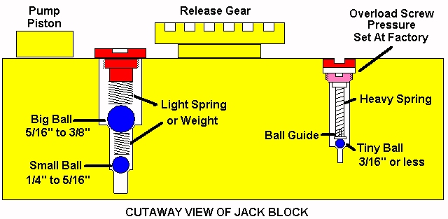
Sorry sir but not this one, please check out the Omega 26030 3 ton aluminum jack owners manual. This is exactly the same as mine. I know my pic is lousy, The only slight difference is mine has a screw instead of a clip per pic. And that"s the only difference, the rest is exactly the same including, YES 2 balls on the overload.
I should of mentioned the one I found first. Then just pure luck would have it I remember reading you recommending Hein Werner and Omega would be good jacks to purchase. So I was looking at the Omega aluminum jacks because I must have Speedy or Magic lift along with a light unit. And the plugger release knob for the handle is a must. I could not believe it when I saw the parts break down that showed 2 balls on the overload, and the same exact diagram that my Craftsman 50239 uses. I saw this all the time as a ASE mechanic, mid production changes that drove us bonkers. Now retired I dabble. But mark my words, 2 balls on this unit. Proof is how every lifting test passes.

A hydraulic jack serves one fundamental goal: the lifting of heavy loads. Jacks are designed to provide force multiplication to enable a worker to amplify their strength through the jack"s hydraulics or mechanics to accomplish this goal.
There are two main types of jacks commonly in use; one type uses hydraulic pressure for lifting (hydraulic jacks), while the other uses a screw thread to achieve lift (mechanical jacks). Of the two, hydraulic jacks usually provide higher lift capacity and are more reliable.
Hydraulic jacks are available in two varieties: floor jacks and bottle jacks. Floor jacks have a horizontal shaft that pushes on a crank. The crank connects to a lifting pad that rises vertically. These jacks are capable of lifting several tons.
Bottle jacks have been around longer, and their name derives from their resemblance to an old-fashioned milk bottle. Bottle jacks have a vertical shaft that raises a platform called a bearing pad. They can lift up to several hundred tons, depending on the specific capabilities of the model being used. However, these jacks typically cannot lift the load to the same height as with a floor jack.
Both types of jacks operate under the same basic principle: In a closed container, the pressure is the same in all directions. In the case of a hydraulic jack, this container is a cylinder, and it holds incompressible hydraulic fluid. Hydraulic fluid is forced into the cylinder through a check valve that prevents the fluid"s backflow. The check valve keeps the cylinder pressurized so the load does not drop. As pressure builds in the cylinder, the force pushes upward on the plate of the jack and lifts the load resting on it. The weight of the load lowers the plate when the check valve is released, allowing the hydraulic fluid a path to exit.
There are some issues that are common to all types of hydraulic jacks which can impact their operation and safety. At some point, users will likely encounter leaks, rams that won’t lift, safety valves that get tripped, damage to the frames, and jack handles that kick back. While many hydraulic jack repairs are easy to accomplish, others might require the assistance of a professional.
Leaks, in particular, are extremely common, and result from a failed or dislodged seal or O-ring. Repair involves draining the hydraulic fluid, disassembling the jack, and inspecting the seals. Be sure to look carefully for cuts, tears, seals that are out of place, degradation, scratches, and so on. These issues are an indication that the seals or O-rings need to be replaced.
Repairing leaking seals can be a significant undertaking, especially for those not experienced in jack repair. Novices might want to leave this type of issue to a professional with the requisite experience. Also, if the leaked fluid is cloudy or foamy, that indicates the presence of water or air in the hydraulic system and could mean that the hydraulic fluid needs to be replaced and the potential source of the intrusion investigated.
Jacks may also be overloaded, causing the safety valve to trip. The purpose of this safety feature is to prevent the jack from being loaded beyond its rated operating pressure, typically measured in pounds- force per square inch (psi). A jack will not behave the same way after the safety valve has been tripped. The ideal way to address this issue will vary by manufacturer, so always consult the service manual when this occurs. Professional service is recommended in these instances to restore safe operation of the jack.
In other cases, rams may stop lifting, which is usually the result of insufficient hydraulic fluid in the reservoir. Luckily, this is a repair that even beginners can handle. When there isn’t enough hydraulic fluid present, air may become trapped inside of the system. The solution here is to add the appropriate amount of hydraulic fluid, then turn the jack to its release position. Next, pump a few times to purge out the trapped air. Then, refill the reservoir and place the seal cap back on. Be careful to avoid introducing contamination (such as dirt and dust) to the hydraulic system while adding fluid, and never mix two different types of fluid.
Hydraulic jacks are powerful devices for lifting, but like any other mechanical or hydraulic system, they will inevitably require maintenance and occasional repairs. While someone with fundamental mechanical skills may accomplish some repairs, others are best handled by a hydraulic professional. Be sure to consider the options carefully before deciding on a course of action.

Maxton recommends that if you aren’t successful in troubleshooting or adjusting a valve setting in 20 minutes, stop and call Maxton tech support 1-775-782-1700.
Proper valve adjustment optimizes the energy efficiency, ride, performance of the pump, motor and overall hydraulic elevator system. Add life to your elevators…make sure the elevator control valves are adjusted within optimal ranges using files below or download the Maxton Mobile Mechanic app.
The present invention relates to an improved safety valve structure for a hydraulic jack, particularly to an improved structure of the safety valve inside a pump base of the jack so that high pressure hydraulic fluid can smoothly and accurately flow through the valve and return to a reservoir.
A one-way valve is usually provided between the reservoir and the pump base of a hydraulic jack. The one-way valve is used to control hydraulic fluid flowing from the reservoir into a pump. The valve also cooperates with the up-and-down movement of a lever on the jack so that the hydraulic fluid can be forced into a pressure tank for pushing a piston upward. When the jack is overloaded and the hydraulic pressure inside the jack has reached a predetermined limit, a safety device is needed to discharge the hydraulic fluid back into the reservoir. A conventional safety device uses a steel ball and a safety spring secured by an adjustment screw. The adjustment screw is used to adjust the pressure of the safety spring which presses against the steel ball. When the pressure inside the pressure tank is higher than the pressure of the safety spring set by the adjustment screw, the steel ball will automatically be pushed rearwardly against the force of the safety spring so that the safety spring is compressed, thus enabling the steel ball to disengage from a valve seat. Thus, the path previously closed by the steel ball is opened and the hydraulic fluid can return to the reservoir, thereby lowering the pressure within the pressure tank and preventing the pressure tank from cracking or exploding. However, the operation of the above arrangement is not reliable, since it is easy for the steel ball to deviate from an opening path of movement. Therefore, discharge of the hydraulic fluid is unstable and results in rough operation.
The main object according to the present invention is to provide an improved safety valve structure for hydraulic jacks. The structure is provided with a push pin, a safety spring and an adjustment screw. The end of the push pin is placed inside the axial hole of the adjustment screw. The adjustment screw is used to adjust the compression of the safety spring so as to control the pushing force of the push pin. By such configuration, the push pin can be used to seal the opening as well as to guide the hydraulic flow when the push pin is retracted. Thus, it provides for smooth operation when the hydraulic oil is discharging.
As shown in FIGS. 2 and 3, a safety valve according to the present invention is provided inside a valve body of a one-way valve 1 of a hydraulic jack. The one-way valve 1 is provided inside a pump base 6 of the hydraulic jack and a pump 7 is provided on the pump base 6. The one-way valve 1 includes a cylindrical valve body. The cylindrical valve body has an annular recess or slot 11 formed in an exterior wall thereof.
An L-shaped oil inlet channel 12 defines an oil inlet port 121 at slot 11 and a port opening at the top surface of the one-way valve 1. A filtering screen is provided in the inlet channel 12 at oil inlet port 121. The L-shaped oil inlet channel 12 is a two-step channel having a larger diameter portion at the top and a smaller diameter portion at the bottom. A steel ball 123 and a compressed spring 124 are provided in the larger portion of the channel. The compressed spring 124 engages a projection defining the upper opening so as to be secured without disengaging. Also, the steel ball 123 seals the upper neck opening of the smaller diameter portion of the channel. In addition, the top surface of the one-way valve 1 is provided with an oil discharge port or hole 13, which is a two-step passage or hole having a larger diameter bottom portion and a smaller diameter top portion. The larger diameter portion of the channel is provided with a steel ball 131 and a compressed spring 132. The compressed spring 132 is secured in place by engaging an inwardly extending projection defining a bottom opening. Also, steel ball 131 seals the bottom opening of the smaller diameter portion. In addition, the wall of the annular slot 11 of the one-way valve 1 is provided with a safety oil discharge port or hole 14, which communicates with the smaller channel portion of the oil discharge port or hole 13.
As shown in FIGS. 2 and 3, the safety oil discharge hole 14 is a two-step passage or hole having a smaller diameter portion 141 which communicates with the smaller portion of the oil discharge hole 13. A rearward section of a larger diameter portion 142 is provided with inner screw threads. A push pin 2, as well as a safety spring 3, are placed in the larger portion 142 and an adjustment screw 4 is used to secure the pin 2 and spring 3 in place. A forward portion of push pin 2 is a cone-shaped body 21 and a rearward portion is a two-step rod or post 22, in which a large-diameter portion is inserted into the safety spring 3 in the axial direction, the small-diameter portion is inserted into an axial hole 41 of the adjustment screw 4. In this configuration, the resilient force of the safety spring 3 is applied so that the cone-shaped body 21 of the push pin 2 seals an end of the smaller portion 141 of the safety oil discharge passage 14. An end of safety spring 3 is engaged by adjustment screw 4, which is screwed and secured inside the larger portion 142 of the safety oil discharge hole 14. Also, the force of the safety spring 3 and thus the sealing force of push pin 2, can be adjusted by adjusting the adjustment screw 4 in the larger portion 142 of the safety oil discharge hole 14. In addition, the axial hole 41, provided on top of the adjustment screw 4, is used for discharge of the hydraulic fluid.
By use of the push pin 2, provided in the safety oil discharge hole 14 to cooperate with the safety spring 3 and the adjustment screw 4, the pump 7 can be removed and the one-way valve 1 can be taken out. By turning the adjustment screw 4, the compression ratio of the safety spring 3 can be set and the force of the push pin 2 acting against the smaller portion 141 of the safety oil discharge hole 14 can also be adjusted. Thus, the force from the safety spring 3 pushing against the push pin 2 can be set as the critical value of the hydraulic safety load coefficient. In other words, safety spring 3 and push pin 2 limit the pressure of the hydraulic jack. During operation, when the safety load value of the hydraulic fluid within the jack reaches the limit (i.e., when the load exceeds the setting of the push pin 2), the push pin 2 inside the safety oil discharge hole 14 is displaced backwardly by the hydraulic pressure and compresses the safety spring 3. At this time, the push pin 2 disengages from the smaller portion 141 of the safety oil discharge hole 14 and therefore, the hydraulic circuit is a closed circuit. This means that the hydraulic oil can circulate through the safety oil discharge hole 14, the axial hole 41 of the adjustment screw 4, the annular slot 11 of one-way valve 1 and return into the oil storage tank, allowing the pressure inside the jack to be depressurized. When the pressure inside the hydraulic jack decreases to within the safety load limit, the force from the safety spring becomes higher than the internal hydraulic pressure of the hydraulic jack, and therefore, the safety spring 3 automatically biases the push pin 2 forward so as to seal off the small portion 141 of the safety oil discharge hole 14. By this setup, the safety of the hydraulic jack can be assured and an explosion can be prevented. In addition, the push pin 2 is a linear fluid guide inside the safety oil discharge hole 14. When the latter is discharging, turbulence is prevented and a smooth operation can be assured. It is indeed a compact, practical and modern design.
By use of the above configuration, the flow of the hydraulic oil is described as follows: when the lever 5 is pulled up, the hydraulic oil inside the reservoir is sucked through an inlet 61 inside of the pump base 6. The oil follows the L-shaped oil inlet channel 12 and flows into pump 7. When lever 5 is pressed downwardly, hydraulic oil inside pump 7 is forced out through oil discharge hole 13 of the one-way valve. The oil follows an outlet path 62 of pump base 6 back into the pressure tank of the hydraulic jack so as to drive a piston up for lifting (now shown in Figure). However, if the lifting load of the jack exceeds the maximum design load and a user continues to operate lever 5 to force hydraulic oil into the pressure tank; the pressure could cause the pressure tank to crack or explode. Therefore, when the hydraulic pressure exceeds the safety limit, the improved safety valve structure, according to the present invention, allows the hydraulic pressure to push the push pin 2 inside the safety oil discharge hole 14 backwardly so that the hydraulic oil can follow the path through the annular slot 11 and through the inlet path 61 of the pump base and then return into the oil reservoir. Thus, the pressure inside the pressure tank can be controlled. In addition, the structure of push pin 2 provides a linear fluid guide so that the oil flow is smooth and accurate.

Thanks for the information. I don"t mind the long reply, and don"t consider any of it useless. I always use jackstands, because as you mentioned, jacks can fail. You know, I have to take that back. If I"m doing something where no part of me will be under the vehicle, I often forego the jackstands, though I know I shouldn"t, even then.
I always find the physics side of things interesting. That was always my favorite subject in school. Probably why I like mechanical "things". And yeah, a cylinder is a cylinder. A jack just has an integral pump. Taking it apart shouldn"t be unmanagable. I find that a solid vice and a pipe wrench (and maybe a cheater) are enough to take bottle jacks apart.
(Remember my attempt to invert one? That, BTW, didn"t quite work. I needed to relocate the reservoir above the pump. Also, the pump leaks like crazy now, though I don"t know why, and I didn"t take it back apart to find out. The problem I really ran into is that when inverted, using a pickup tube with no check valve at the bottom of the tube, the hyd fluid runs back out of the tube and it fills with air. So, something somewhere isn"t quite sealing. Chalk $10 up to fun. Anyway, back to this jack...)
I don"t seem to have any trouble with not getting a full stroke of pumping out of it. The ram seems to come back normally, but does not leak down. The fluid is new, or at least it was at one time not too long ago. It did not seem to affect how the jack works. However, it does seem to make more sense than a seat that is worn since it works sometimes. I don"t know if I have ever tried it without the plug in. I can remove it and see if it makes a difference. I suppose if one of the check [email protected] is the problem that could make it intermittent, depending on how the [email protected] rotates. Maybe I"ll pull the two plugs on the left and just have a look/see.


 8613371530291