
floor jack safety valve adjustment free sample
An overload valve of a floor jack primarily exists so that the jack does not exceed the weight limit of the hydraulic press, which might cause it to break down. Overload valves stop the press from lifting further up if the weight limit is crossed.
The floor jack overload valve adjustment process is very straightforward and only requires you to follow a set of simple steps. However, if you’re trying to adjust the overload valve, chances are that your floor jack is having some trouble holding pressure. In that case, we have some solutions for that as well.
An overload valve is a safety measure to protect the hydraulic press from unwanted damage due to excessive pressure. It works by loosening the connection between the jack handle and the hydraulic press.
When we’re talking about adjusting the overload valve, we’re mainly changing the max weight capacity of the floor jack. To do that, you just need the right screwdriver. It varies from model to model, some use Philips heads while others use binding heads.
Once you’ve got the right screwdriver, find the location of the safety valve. There will be a shield on top of it that you’ll have to remove with the screwdriver. Spot the screws and turn them counterclockwise to release the shield.
After you’ve done that, the valve should be exposed to you. There are mainly two types of valves used on floor jacks. The handle valve and the screw valve. Handle valves have a handle, while screw valves have a hole for the screw to go through.
For a handle valve, you just have to hold on to the handle and rotate it to adjust the weight overload on the floor jack. Rotate it clockwise to increase the maximum weight capacity and counterclockwise to decrease it.
These valves are typically very sensitive so a small turn could drastically change the output. So, try it in small amounts and figure out the correct amount for you.
For a screw valve, you will need a corresponding screwdriver. Typically it is the same as the shield’s screws, but according to your model, it could be different.
Safety Note: Before attempting to put pressure after adjustments, check the instruction manual of the floor jack for the maximum supported weight capacity. Normally, the valve will be set to 90% of that max capacity. So, you can at best increase it to 100%. Going beyond that will be very risky as it can damage both the floor jack and your vehicle.
This is a very common issue for which people consider adjusting the overload valve. A loose valve can indeed cause your floor jack to suffer such problems. However, that’s not the only cause.
The hydraulic press will fail to operate if the oil levels are above or below the given margins. Also, if the oil is of low quality, it might cause friction which can also prevent it from working properly. To maintain the proper hydraulic level, you should fill your jack with oil correctly and safely.
To know exactly what types of fluid are used in a floor jack, check out this article where we have explained and recommended the hydraulic fluid to use in your jack.
Hydraulics work by using highly pressurized compressed air. After long-term use, some of that air can leak into other parts of the machine causing havoc. The air mostly gets trapped in the oil chamber. To remove air from the floor jack, you just need to bleed it.
The final most obvious consideration would be that the floor jack is damaged. In most cases, it’s the hydraulic press. Repairing a broken floor jack is not worth the effort and the money. You’re better off getting a new floor jack.
Keep in mind that the overload valve is a safety measurement. So, a floor jack overload valve adjustment should only be done under your own circumstances. To be on the safe side, never exceed the given weight limit of your floor jack.

The YA700 has a 2 1/2 ton capacity. I"m going to present a lot of photos with a few comments. I hope the photos are detailed enough to give you an idea of what tools and techniques I used to tear the jack down. The steps I give are the exact order that I used to disassemble the jack. This same procedure can be used on the 2 ton YA642C and also the Lincoln/Walker 93642 series C service jacks. The only difference being the heel plate and u-cup on the end of the ram.
Using snap ring pliers, remove the clips and washers from both wheels and then slide the wheels off the axle. This step isn"t really necessary, but as I have pressure washed the entire jack I want to make sure to clean and lubricate the axles before I reassemble.
First step in getting the hydraulic unit out of the jack is to remove the 2 nuts and lock washers on either side of the main fulcrum pin and also the 4 bolts securing the hydraulic unit to the frame. The side plates on this model are welded to the front axle but it is not necessary to do anything further at this point.
I can"t stress enough how important it is to secure the jack in such a way that it has no movement. You will see why when you go to remove the tank nut. Do NOT hold the hydraulic in any way that involves the oil reservoir, that"s the round tank you see with the air vent in the top. This is relatively thin metal and can be crushed in the process of putting it in a vice.
Nothing special here, just unscrew it from the base of the hydraulic unit. It"s rare to see any thread damage on these or even the o-ring damaged. This model has what"s called a plastic spring in the end of it (that little white dot in the center of the threaded end.) The spring is worn on this one to the point that it no longer functions and I know from experience that it is going to be difficult to get out, but more on that later on as I will show you what I do to remove it. By the way, it"s purpose is to keep a little spongy feeling when you close the release valve and it prevents the two metal surfaces from sticking together. When they are worn out, the release can sometimes be hard and "pop" loose as opposed to smooth and easy. Such quality engineering in jacks has all but disappeared in import jacks.
The first view is off the overload valve. You can see an adjustable screw toward the bottom. The other side with the screw near the top is a pressure plug. It is not adjustable.
Like I said, it can be very messy in these old jacks that have never been serviced before. Somewhere in this mess will be a filter screen. A few of the internal parts may have fallen out at this point, so gather them up.
At this point in the repair, I wipe off some of the gunk and oil so that I can get a grip on the ram cylinder. After I grab the cylinder, I turn the hydraulic upside done on my vise table and give it a good rap on the table to get all the internal parts to fall out. It is generally the overload assembly that comes out last. The parts on the valve side should fall out pretty easy (if they are not already out.) Make sure on the overload side that you continue until you retrieve a small ball that is the last piece to come out of the hole. If it doesn"t come out after rapping it on the table, you can use a small magnet. Occasionally, the ball can be stuck on the seat at the bottom of the chamber. If this is the case, you will have to break it loose with the tip of a screwdriver before it will drop out.
Here I secure the unit by the cylinder in my pipe vise. Once secure, I slip a small strong steel rod through the hole in the tip of the ram. Next I pull (or yank) until the ram comes out of the jack.
In the first photo it is not real obvious, but as the second photo reveals there is a split in the u-cup. I see this all the time in older jacks where the u-cup is brittle and it has either cracked or broken up into several very small pieces. Behind the u-cup is the heel plate and behind that is a steel backup washer. If you look carefully at the heel plate before you remove it, you will notice that there is a top and bottom to it. The rounded edge should be facing up (away from the u-cup.)
At this point in the repair I do some general cleaning of the parts so that I can get a better look at the ram cylinder walls, valve seats, etc. I just use 100% mineral spirits and air pressure to do the general cleaning. For more intense cleaning, I use a wire brush, wire wheel, flex hone, and emery paper.
I can see from this inspection that the ram cylinder is going to need some very light honing. Although you can"t see it in the photos, I get a much better look at the valve seats by using an otoscope (such as an ear doctor would use.) What I am looking for are nice clean and round surface areas where the valve ball sits in the impression on the hole it covers. Sort of hard to explain what a bad one looks like as it can be anything from rust, pock marks, or the hole wobbled out over time. All of these things can be dealt with by making a clean new seat which involves drilling the old seat out. These seats look good so I am going forward.
The ram sides have nothing to do with the performance of the jack since all the pressure is on the end. It is important to keep the sides clean and smooth so that the seal in the tank nut stays in good shape. The tank nut seal keeps the oil contained inside the reservoir. The only time there is pressure inside the oil tank is when the jack is being released and it is refilling with oil coming out of the ram cylinder. This pressure should be quickly dissipated by the air filter/vent.
This cylinder needed a little more than just cleaning with a rag, it wasn"t pitted or corroded yet and I caught it just in time. Generally what happens is, that the jack goes bad while sitting in a corner for months or years without use. I personally think it might be a good idea to pump a jack up and down every so often (good or bad), so that the oil doesn"t have a chance to sit in one place and cause damage. I"m pretty sure this would help, as most of the damage I see to the inside and outside of the ram cylinder appears to be from oil that may have pooled up and set too long. I have seen corrosion on the outside of a cylinder so severe that it ate a hole thru to the inside of the ram cylinder.
Nothing special here. The u-joint that is attached to the release stem on this jack is in good shape, but they are not always that way. The u-joint must be inspected for freedom of movement. If it catches in any direction it may give the operator the feeling that the release is closed off. If the pins are in danger of falling out, they can sometimes be re-peened. If the pin cannot be re-peened, I have seen some come in with a small nail through the body and then bent over. I usually put a small metal screw through the body and then peen it near flat. The head of the screw can be slightly ground off to remove the slot. It makes a nicer looking job than a nail.
I made a special step of this because it doesn"t always go as easy as it may seem. First of all, if it is long enough to grab, I just pull it out using my finger nails. Yeah! If that doesn"t work, I try blowing a small stream of air right directly at it. About 25 percent of the time that actually works and it goes flying across the room (safety googles!)
all old seals etc. have been removed, and all valves and orifices have been cleaned. With the cause of the malfunction identified (a cracked and brittle u-cup,) I can now proceed with confidence installing the new repair parts.
The 1st picture is from Step 23. It shows the proper order to replace the new and used items. The 2nd picture shows the hydraulic after the parts have been installed. The pressure plug on the right is tightened with the same impact screwdriver I used to break it loose (see step 19.) The overload adjustment screw I tightened down all the way to bottom and then backed it off 1 and 1/2 turns. This gives me a general starting point for the overload valve to pop off at.
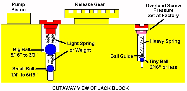
The 1st photo is a general representation of how most service jacks work. The 2nd photo shows a comparison of good and bad ball seats. It"s important at this time to feel confident about the valve seats. If you experience the following symptoms after the repair, these illustrations may help.
1. If the jack handle drops down of it"s own accord - there is an issue with the suction valve. This is the valve on the bottom with the smaller ball.
I had done general cleaning of this earlier, but now it"s time to get "picky." Everything must be cleaned and rechecked. A tiny piece of debris in the valve chamber can cause a failure to lift and/or hold.
As mentioned earlier, both ends of the tank are metal to metal mating. Thanks to the fine engineering and quality control that went into these old American made jacks, I can"t remember any of them leaking in this area. In lieu of varnish, I put a very thin coat of sealant on just one surface of both ends. You can barely see the sealant on the tank nut.
It"s a simple job that would be much harder had I not a way to secure it tightly. I use an old jack handle on the end of a 3/4" breaker bar to tighten the nut. Notice how the vent hole is now aligned on top center. I did not just stop at that point once I saw that it was lined up. It is a trial and error process that ends when I can not tighten it any further.
First be sure to drop the cone shaped release valve into the release valve hole. Double check to make sure it did not turn sideways or flip completely over before inserting the release stem into the hole. I put some oil on the o-ring and the plastic spring prior to insertion.
So for many years I have mixed up a 50/50 blend of 120W oil and STP oil treatment to use as a lubricant for every moving part of the jack (except for the ram and u-cup.) There are upper and lower caster balls, wheel holes and axles, pump roller, handle end and socket, handle retention bolt, and any moving part or friction area I can find. Yes, the oil is still pretty fluid and will drip off, but what stays behind last for a long while. It silences the caster bearing noise and makes the rolling around feel very smooth.
This model holds about 10 ounces of hydraulic fluid (or about 1 squeezable plastic ketchup bottle.) Start with the lifting arm in the down position and with the release valve open. If you look through the vent hole you can see the ram cylinder. Add just enough fluid to cover the ram cylinder and then stop. Too little oil and the jack will quit lifting after the oil runs out. The jack will still hold a load but the pumping action will feel spongy due to the fact that it will be pumping air into the cylinder instead of oil. Too much oil and the oil will try and squirt out the vent hole when the air in cylinder is displaced by the returning oil. This leads to the next step, which is the job of the vent plug.
I have a means to test service jacks such as this, and make sure the the overload is set properly. If anyone is following along with this, I have a word of caution. If you reset the overload to where you found it, you are more than likely okay. On this particular model (it is just my observations and personal opinion) that the length of the ram is too long and will bend slightly if overloaded. If the overload is set properly you will not have any problems. I have seen several of these with a bent ram. Symptoms would be the lifting arm stopping part way down (without a load) and then continuing with a little assist. Worst case scenario, the lifting arm won"t come down at all. Also, I have seen the pump handle bent. Keep this in mind, if you are lifting something and it gets too hard too pump, the overload should have gone off BEFORE you got to that point!
I assume you are referring to the plug in step 19. In answer to your question - it depends. If you feel like you already found a problem that was causing your jack to fail (as in a bad u-cup) then you may be okay. Best of luck!0
First I would like to thank pitg2000 for the instructions! What a lot of work that would be and it sure helped me (and others). The day after I sent my question I realized I didn"t have to remove the piston to remove the leather cups and I did exactly as you described. Didn"t want to risk damaging anything by driving the pin out and it wasn"t necessary. Have the jack back together and the pump piston won"t return by the spring alone but when I tap on it it comes right back. I will loosen the 5/16 packing nut tomorrow. I have a Japanese Shur-lift jack I bought at the same time as the YA700 38 years ago. It still works but as soon as the kit comes in I will rebuild it. I have the upgraded bleeder for the YA700 coming with it Once the YA700 is operational I will rebuild the other one. I consider myself a "hyper maintainer" but I didn"t know to change oil in the jacks. I will now!
Thank you for your comments! I am sorry that I had not seen the post sooner and could have helped you when you actually needed it. I am glad you figured it out anyway. Yes, the pump sticking down is more of a problem with the packing being provided now. The old original packing appeared to be more "waxy." I think they were made from a softer leather that had been soaked in wax (just guessing.) They installed much easier. I dip the packing in oil before installing them and snug them down tight. After snugging them down I back them off just a little. When you go to use the jack and the pump sticks down it "might" loosen up after several times. Good luck!0
Yes, definitely! In my opinion, the heel plate is what could prevent a catastrophic failure of the jack. You see if the u-cup fails, oil will then be trying to get by the heel plate. The slower this process is, the slower the load will come crashing down. The heel plate isn"t a seal, but it is fairly snug to the cylinder wall. I"m not sure whether I am making myself clear or not, but do replace the heel plate.0
At first I thought you"re instructions were great, but soon found out my Snap-On model ya700 2&1/2 ton jack was different in some ways. Also the instructions did not cover removing the handle. Also did not mention a bar located just in front & above the main fulcrum pin, which is welded on both sides, making it imposable to continue with out laying the jack on its side to access the pin.
Sorry that I neglected to tell you how to remove the handle. The jack belonged to a customer of mine and I can no longer take any pictures. I have also retired so I don"t have anymore jacks in my shop. All is not lost though, I see in step 4 that I happened to get a shot of the bolt that holds the the handle in place. I have included in this post a picture of how to locate the bolt. As I recall, it has a 9/16 " hex head. Some of them are just hand tight, so you might try turning it counter-clockwise far enough so that the handle can be pulled up and out. If it is too tight, you will have to use an open end wrench or socket. Hope this helps.
As for the welded in place bars and the pin, you may be referring to the lifting pad levelers and a cotter pin that extends through the tip of the ram. If that is the case, see step 5 to get the power unit in a position so that you can remove the pin in step 7. Hope that helps. Please feel free to included some photos of your jack and I may be able to clarify things better.
You see the Jack isn"t mine, & was talked into the rebuild. I too am retired (USMC), no mechanic & 76 years old. so when I noticed there was no mention of the handle it made me wonder what else is missing in the instructions.
After a ratchet-and-socket set, box-end wrenches, and screwdrivers, the most commonly used automotive DIY tools are probably a floor jack and a set of jack stands. Whether you’re changing a flat tire, replacing brake pads and rotors, or performing work under the vehicle that requires it to be raised for clearance or comfort, it’s important to understand that the functions of floor jack and jack stands are tightly intertwined.
That is, you use a floor jack to lift the nose or tail of a car (or, possibly, just one wheel), then you set it on jack stands to keepit safely in the air.
Last year, low-priced tool giant Harbor Freight recalled several of its jack stands due to instances of the stands slipping under a shifting load. It pushed the issue of jack stand safety to the automotive media’s front burner, which is certainly a positive thing. I thought I’d give you my common-sense perspective on floor jack and jack stand safety.
Before I delve into the mechanics of the slippage of the Harbor Freight stands, we need to jump into the Wayback Machine. If you wrenched 30 years ago, the jack stands you likely used had a design consisting of two sliding stamped metal tubes like the ones pictured below. The bottom of the outer tube was slit in three places, and the resulting sections were bent outward to create three legs which had metal bands welded to the bottoms to secure them against splaying apart further under load.
The inner height-adjustable tube had a cradle on the top to hold whatever part of the car it was under, as well as several holes that could be aligned with a hole in the outer tube and locked with a metal pin that was the diameter of a pencil. Stands like this were inexpensive and lightweight, but the stamped metal was fairly thin, the increment of height adjustment with the holes was usually pretty coarse, and using the stands meant putting them under your jacked-up car, raising the inner tubes, lowering them until one hole aligned with the hole in the outer tubes, and manually sliding the pins through. The pins actually performed three separate functions—selecting a height, locking that height in place, and supporting the weight of the car—but this wasn’t really trumpeted as an advantage.
The stamped metal-pinned tubular jack stand was gradually replaced by a welded ratcheting design. Instead of having two sliding stamped-metal tubes with their location fixed by a pin, the ratcheting design has a post with teeth, which slides up and out of the middle. This ratchet works like the familiar ratchet in a wrench, except it’s linear instead of circular. Teeth on the post are a right-triangle sawtooth shape with the short edge parallel to the ground. As the post is lifted up, a “pawl”—a curved eyebrow-shaped bar—has one end that pivots, and another end that slides under the part of the tooth that’s parallel to the ground, making it so the post can be pulled upward but can’t be lowered without flipping the release bracket. It’s a bit quicker to deploy beneath a jacked-up car than a pinned stand.
In addition to the ratchet itself, the construction of a ratcheting stand is heavier and thicker than the pinned stamped-metal tubular one. Typically, a thick metal plate is bent into a four-legged shape, welded onto itself at a seam, and welded at the top to the central body that receives the toothed post. If you accidentally run over a stamped-metal tubular stand, odds are you’ll flatten it, or at least bend the legs. In contrast, if you accidentally run over a ratcheting jack stand, odds are you’ll damage the undercarriage of the car.
In May 2020, low-priced tool giant Harbor Freight recalled 1.7 million of its Pittsburg-brand three-ton jack stands (items 56371) and six-ton stands (items 61196 and 61197) due to reported instances of the stands slipping while under load. You can find videos on YouTube where people demonstrate this under controlled conditions. This video of a disassembled jack stand does a pretty good job of showing the mechanics of the problem—the end of the pawl not fitting as securely under the teeth as it should. And on this website, you can see photos in which someone put white paint on the pawl, and a surprisingly small amount of paint transferred onto one of the teeth on the shaft, which demonstrates the small amount of overlap of the pawl under the teeth.
The root cause of the problem was reportedly traced to aging tooling at one factory run by the manufacturer, the Jiaxang Golden Roc Tool Company, affecting reportedly about 5 percent of the jack stands manufactured there. There were reportedly 11 injuries caused by the problem, none of them life threatening.
Unfortunately, Harbor Freight’s replacements for the recalled three-ton stands (item 56373) had a different problem—instances of the seam weld cracking when under load. These were recalled as well. You can find videos of this “zipper failure” of the seam weld on YouTube. Together, the recalls created the impression that any Harbor Freight jack stand was going to kill you.
An unintended but completely reasonable response to the Harbor Freight jack stand debacle was a sharp resurgence in interest in tubular jack stands, where a thick and plainly-visible pin is used to set the height, lock the stand, and support the car’s weight. Although the cheap lightweight stamped metal design is a thing of the past (and rightly so), sales of pinned-design jack stands such as this Torin T43004, with two sliding aluminum tubes and a screw-on aluminum base, soared. In addition to having a locking pin instead of a pawl, the screw-on base means that this particular design is even free of the kind of weld that failed in the second Harbor Freight recall.
Ratcheting jack stands, however, have not gone away. Far from it. In fact, many if not most new ratcheting stands have had a makeover, receiving a manually-insertable safety pin that provides redundant load bearing to the ratchet pawl. If you want to buy new ratcheting stands, you’d probably need to go out of your way to find one that doesn’thave this “double-locking” feature.
Obviously, the Harbor Freight jack stand recalls are a very serious issue, and if you have Harbor Freight jack stands from one of the recalled batches, you should return them. But should you toss your current ratcheting jack stands in the recycle bin and pony up for one of the newer pinned-tubular stands or a ratcheting stand with a redundant pin? If you’ll never feel safe working under a car unless you do, sure. But if that’s allyou do, you still won’t be as safe as you could be.
With that said, I’ve been wrenching on my own cars for 40 years and writing about it for 35, and in my Hack Mechanic opinion, the dominant safety issues working under a car are these, and they remainthese, even after you’ve exchanged your Harbor Freight jack stands:
Always, always,“double-jack” the car. I can’t write this often enough or say it strongly enough. The single most important thing you can do to make working beneath a car as safe as possible is that, after you’ve used your floor jack to raise the car and set it down on jack stands, leave the floor jack in place as a back-up.This is literally zero extra work, and it costs you nothing. I realize that, at times, the floor jack may then be in the way, but consider approaching the part you need to work on from another angle.
Always jack up the car on a level surface, never on an incline.You’d think you need to be suicidal or an idiot or both to jack up a car on a hill, but people sometimes make poor choices in the heat of the moment. I was a physics major in college and had a mechanics professor—that’s “mechanics” as in the study of the forces on moving and stationary objects—who died when his car fell on him. Months after it happened, I looked at his driveway and was astonished at its steepness. What caused him to do it, I don’t know. The best, smoothest, most level, safest place to jack up a car is usually your concrete garage floor. Maybe there was already a car in his garage and all he wanted was a quick oil change. Who knows. That a mechanics professor could get this wrong enough to get himself killed haunts me to this day.
Don’t jack up a car on asphalt, especially on a hot day. Asphalt is never as hard as concrete, and as its temperature increases, it can get soft enough that a floor jack and jack stands can sink right in, causing a car to topple. Combine it with a surface that isn’t laser level and things can go sideways very quickly. I’ll never forget checking out a car I was thinking about buying. I met the seller in a CVS parking lot in July. I’d brought an aluminum floor jack and used it to put the nose of the car in the air to quickly wiggle the front wheels and check for front-end play. I didn’t “double-jack” the car because I wasn’t even pulling the wheels. I didn’t perceive the parking lot as slanted, but it was, and the slant was at a right angle to both the car and the jack, and that—combined with the hot temperature and the soft asphalt—caused the jack to sink and the car to topple, with the nose abruptly jumping one foot toward me. My body was never under the car, but it scared the bejesus out of both me and the seller, and I’ve never forgotten it. If you have no place other than asphalt to jack up a car and have absolutely no other choice, I strongly advise making sure it’s dead flat and putting metal plates beneath the floor jack and all jack stands.
Once settled, check the jack stands. Once you’ve released pressure on the floor jack and let the car down on the jack stands, check the stands both top and bottom. Make sure that the part of the car the cradle (at the top of the stand) is touching is in the middle and is sitting flat, and verify that all four legs of the base of the jack stands are sitting securely on the ground. This is especially crucial if you’re trying to put all four wheels of the car in the air, as the act of jacking up one end of a car can easily cause stands already at the other end to tip forward.
Don’t overload the jack or the stands. I’ll talk about load ratings below, but basically, don’t be an idiot and jack up a truck with a little jack and then set it on little stands.
Don’t rock the cradle.Once the car is up on stands, give it a few good shoves from all four sides. Any motion should be barely perceptible. It certainly shouldn’t sway. (Note, however, that some owners of pinned jack stands report that, due to that circular pin, they do sway more than ratcheting stands, where the pawl rests on a squared-off tooth). However, once you’re under the car, do notrock it. It can be surprisingly easy to set up a resonant harmonic motion if you’re doing a lot of shoving, such as while installing a transmission and trying to line up the splines and seat the input shaft in the pilot bearing.
Jack stands manufactured after 2015 should be rated in pairs. That is, a pair of three-ton jack stands should together safely support 6000 pounds. The ratings come from the American National Standards Institute (ANSI) and American Society of Mechanical Engineers (ASME). You may see the standards referred to as ASME PALD (Portable Automotive Lifting Devices) and ANSI PASE (Portable Automotive Service Equipment). Stands manufactured to these standards are tested to 200 percent of their rated load for 10 minutes and experience less than 1/8-inch of deformation. However, note that testing is by the manufacturer, not by ANSI or SAME, and merely allows the manufacturer to claim certification of the product line. It is not assembly-line testing of each set of stands.
If you look up your vehicle’s weight in the owner’s manual or online and divide that by two, in theory that’s the minimum load rating you need for a pair of jack stands to support the front or rear of the vehicle. However: 1) for both safety and peace of mind, you probably don’t want to use the minimum, and 2) weight is just one factor. Jack stands also need to reach the underside of the vehicle and support the load in a stable manner, and the higher the stands are extended, the more the vehicle can rock. For example, half the weight of a 6000-pound truck is 3000 pounds, and on paper, even a little pair of two-ton (4000-pound) jack stands exceeds that, but two-ton jack stands are typically short and may not reach the frame rails of the truck even when fully extended.
So, apply some common sense and use the little two-ton jack stands for small passenger cars, three-ton stands for medium to large cars or mid-sized SUVs, and real five- or six-ton truck jack stands for a full-sized truck or SUV.
There are a few ways to think about floor jack load ratings. A floor jack that is ASME PASE 2014-certified should have been tested by the manufacturer to 150 percent of its rating, so as with jack stands, there is a built-in safety factor. It also should have a bypass valve that prevents you from continuing to lift if it’s overloaded. (Safety tip: If it’s getting really hardto keep pumping up the jack, you’re probably close to overloading it.) However, as is the case with jack stands, if you look at the load ratings the wrong way, you can fool yourself into doing things that aren’t safe. It’s important to understand that the physical size of the jack is probably just as important as the numerical load rating, since a big jack is simply more stable than a small one.
Case in point: If you’re only ever using a jack to lift one wheel to change a flat and want to factor in that the wheel could be on the heavy end of the car where the engine is, assume the jack has to safely lift 33 percent of the weight of the car. For a big vehicle like a 6000-pound truck, one-third the weight is 2000 pounds, so, on paper, even the smallest 1.5-ton (3000-pound) trolley jack has an adequate rating. But, as with the jack stand calculation above, this is so misleading that it’s unsafe, as the jack needs to reach the lift point, get the vehicle high enough in the air to lift the tire off the ground and allow a stand to be put under the frame, and do all this in a stable fashion. I simply don’t believe that a little trolley jack with a narrow base can do that repeatably and safely on a big vehicle, no matter what the load rating says.
For this reason, an oft-quoted rule of thumb, cited by Tom and Ray Magliozzi (“Click and Clack” of Car Talkfame) is that a right-sized floor jack should be rated to at least 75 percent of the vehicle’s weight. So, 6000-pound vehicle à 4500-pound (2 1/4-ton) jack. That still feels a little light to me, but the recommendation does say “at least.”
My option is that, as with jack stands, you should use a good dose of common sense and only ever use a narrow little trolley jack to lift one wheel of a small car, use at least a two-ton jack for repeated in-garage lifting of most cars, use at least a three-ton jack for SUVs, and use a real truck jack to lift a real truck.
This could be a whole column in and of itself. Consulting an owner’s manual doesn’t always help, as it’ll probably only tell you where the factory jack points are for the flimsy little jack that comes with the car. An enthusiast web forum is probably the best place to look. The nose of an older car is typically lifted from the middle of the front subframe, and jack stands are typically placed either under the subframe or the frame rails, but on a newer car, these locations may be hidden under cladding, and the plastic jack pads on or under the rocker panels may be best. Be hyper-aware of the rust situation on your car, as the car world is filled with stories of jacks puncturing rusty frame rails.
To a certain extent, with both floor jacks and stands, bigger is better, as bigger generally means a larger load rating, more stability, and higher lift, but it also means heavier, and that’s at odds with portability. If you’re looking for just-in-case floor jack and stands to have in the trunk for a road trip, you want them light and right-sized.
One wildcard is that, if you have a very low car with a jacking point that is far underneath and difficult to reach, you need a low-rise, long-reach floor jack, but the quirky tradeoff is that even though these are big and heavy to have the structural rigidity necessary to achieve the long reach, that very design means they don’t have as high a load rating as an equally-heavy truck jack would have.
I currently own four floor jacks. The biggest is an AC Hydraulics DK13HLQ, which was and still is the cream-of-the-crop of low-rise long-reach floor jacks and has an insanely low 3.15-inch profile. They’re very expensive, but about 10 years back I found a used one locally and treated myself. For reaching the jack point of my BMW M Coupe or playing limbo with the front sway bar of my lowered Lotus Europa, nothing else I own will work. However, due to its long reach, it’s only rated at 2900 pounds. The Harbor Freight 2 1/4-ton jack has been kicking around the garage since it was still called “Harbor Freight and Salvage.” The Pittsburgh 1.5-ton aluminum floor jack gets thrown in the trunk for road trips. It’s a little bigger than the little yellow trolley jack that used to perform that function, but that makes it more stable. I don’t currently have a real truck jack, but then again, I don’t currently have a real truck.
Stand-wise, there are three sets, all of which are ratcheting stands. There’s a set of tall six-ton truck stands that I bought nearly 20 years ago when I needed to put the back of the Porsche 911SC way up in the air to drop the engine. There’s an old set of Harbor Freight three-ton stands that still see the most use. And there’s a set of aluminum stands that get thrown in the trunk along with the aluminum floor jack for road trips. These are all old enough that none have the new “double-locking” redundant safety pin, but since I always “double-jack” the car, I don’t lose sleep over it. I do check the welds on all three sets for any signs of cracking.
If you won’t feel safe working under a car until you have the best most expensive jack stands available, by all means have a look at the D41609 from US Jacks or the ESCO 10498 stands. But once you have them, please remember everything I said above—always double-jack the car, work only on a level concrete surface, do not overload the stands, and do not rock the car.

A car jack is needed whenever you need to raise your car to carry out an emergency repair – such as to change a wheel when you get a puncture – or if you need to spend more time under it, to renew the engine oil or replace the exhaust system, for example.
There are three main types of car jack: the trolley jack, bottle jack and scissor jack. They all do fundamentally the same thing, but in a slightly different way, and some types are more stable than others (as we explain below).
Now locate the car"s jacking points – your Haynes Manual shows you where these are within Roadside Repairs. Your owner manual will also tell you where it is safe to lift the car from.

Designed to reduce contaminants in high-purity applications using hydrogen and methane gas, these valves have a stainless steel and brass body with a smooth finish to reduce dust collection and internal components designed to protect the seal and diaphragm from contamination.

Check valves are the simplest form of hydraulic devices in that they permit free oil flow in one direction and block oil flow in the opposite direction. Check valves may also be used as a directional or pressure control in a hydraulic system.
In Figure 1, oil is flowing in from the left side port, through the check valve and out the right side port. If the pressure equalizes or is higher in the right side port, the check valve will close and block flow in the opposite direction.
The spring rating varies based on how the valve is used in the system. One of the most common locations for a check valve is immediately downstream of the hydraulic pump (Figure 2). Notice that no spring is shown with the check valve symbol.
When used in this application, the spring pressure rating is usually 1-5 pounds per square inch (psi) and therefore not shown with the symbol. In this case, the valve is used as a directional control in that it allows oil flow from the pump to the system but blocks flow in the reverse direction. This is commonly called a pump isolation check valve. This valve serves four purposes within the system, which are detailed below:
The check valve will block pressure spikes back to the pump. Depending on the pressure, oil flows from the pump to the system at a speed of 15-30 feet per second. When a directional is de-energized to block flow or a cylinder fully strokes, the oil is rapidly deadheaded. The pressure in the line can quickly increase by two to three times. The check valve should then close and block the pressure spikes to the pump.
I recall a plywood plant changing four pumps due to cracking of the pumps’ housings. This occurred over a week’s time on the debarker hydraulics. When the plant ran out of pumps, the staff finally took out the check valve and found that the piston and spring were no longer in the valve.
This $150 check valve cost the company $15,000 in replacement pumps and another $50,000 in machine downtime. That was one expensive check valve. The truth is that if one mechanic had looked at the schematic and known why the check valve was in the system, the replacement of the pumps and subsequent expenses would have been avoided.
When a system is shut down, it is important to maintain oil in the lines. In many cases, the pump is mounted below the level of the system valves, cylinders and motors. The check valve downstream of the pump will prevent the lines from draining once the electric motor is turned off. If the oil in the lines drains through the pump and into the reservoir, a vacuum will occur.
Air will be pulled into the lines through the O-rings and seals of the valves and actuators. This can create issues when restarting the system, as the air will need to be bled out.
Some systems have a hydraulic accumulator installed downstream of the pump and check valve. When the system is turned off, there is pressurized fluid inside the accumulator. The check valve will block flow from the accumulator, preventing the reverse rotation of the pump.
You can observe the pump shaft or electric motor fan to verify that the check valve is good. Please note that all systems using an accumulator should have a method of bleeding the hydraulic pressure down to zero psi when the system is turned off.
On many systems, one pump is used as a backup or spare (Figure 3). Each pump will have a check valve at the pump outlet port. The check valve will block flow from the online pump to the offline pump, preventing reverse rotation.
The timeline was so critical due to downtime costs that the pump was still warm when they received it back from the factory. Just prior to installing the pump, we removed the check valve in the case drain line and found it stuck in the closed position. This prevented the oil in the pump case from draining, which resulted in blowing out the seal.
Frequently, a check valve is used for pressure control. A common application is to employ it as a relief valve to protect a heat exchanger (as shown in Figure 4). In this case, the spring rating is usually 65-100 psi.
If the oil is cold, the inlet pressure to the cooler may reach the check valve’s rating. The check valve will then open and direct the pump volume around the cooler. A check valve will also provide protection for an air-type heat exchanger if the tubes become contaminated.
A few years ago while teaching a class at a sawmill, I observed the students doing their hands-on exercises on the edger. Although a check valve was shown on the schematic to protect the air cooler, the lines to the check valve were plugged off. I asked one of the mechanics about it. He said the check valve was taken off years ago and that they had changed the cooler the week before because of ruptured tubes.
When troubleshooting hydraulic systems, most everyone looks for something large to be the problem, such as a pump, valve or cylinder, but every component has a function. Be sure you understand the purpose of the check valves in your systems.

This article is all about valves, and the various types of valves and fittings available. Valves are mechanical or electro-mechanical devices that are used to control the movement of liquids, gases, powders, etc. through pipes or tubes, or from tanks or other containers. In most instances, valves rely on some form of mechanical barrier—a plate, a ball, a diaphragm, for example—that can be inserted and removed from the flow stream of the material passing by. Some valves are designed as on-off varieties, while others allow very fine control of the passage of media.
Material selection plays an important role in specifying valves to ensure the compatibility of the wetted parts of the valve with the fluid or powder passing through it. Sizing is determined by the pipe or tubing diameter, flow rate, and the width between flanges for pipeline valves being installed as replacements.
Aerosol Valves are used for dispensing the contents of aerosol cans. They consist of two primary components, the housing and the stem. Key specifications include the intended application, actuator type, output type, valve size, and materials of construction. Media dispensed can be a consideration as well. Aerosol valves dispense liquids, creams and ointments, gases, cleaning agents, and any other product that is packaged in an aerosol can.
Air Logic Valves are mechanical or electro-mechanical devices used to regulate the flow of air in pneumatic systems and can be used in place of electrical control in instances such as hazardous atmospheres or where electrical control is impractical. Key specifications include actuator type, number of ports, materials of construction, switching speed, port thread size, pressure ratings, and input voltage. Air logic valves are applied to pneumatic systems as e-stops, pilot valves, one-shot valves, etc.
Balancing Valves are used to control fluid flow by dividing flow evenly in multiple flow branches. Key specifications include the number of ports, port connections, valve size, and materials of construction. Balancing valves are used primarily in HVAC applications and fluid power systems. For example, they can be used in commercial heating/cooling systems to adjust water temperatures under varying loading conditions. They can also be used to provide a counterbalancing force for double acting cylinders.
Ball Valves are quarter-turn valves incorporating ported spheres that swivel in the pipe stream to either block, or allow, flow. Special designs are available which enable a degree of flow regulation. Key specifications include the number of ports, port configuration, port connections, valve size, and the materials that make up the valve body, its seat, seal, and stem packing. Ball valves are used practically anywhere a fluid flow must be shut off, from a compressed-air line to a high-pressure,hydraulic system. Ball valves can provide low head-loss characteristics as the port can exactly match the pipe diameter. Ball valves also tend to seal better than butterfly valves, but they can be costlier to purchase and maintain. Typically they are actuated with a lever which provides a visual indication of the valve status.
Blind Valves, or line blind valves, are mechanical devices used to stop flow through a pipeline. They are used primarily by the oil and gas industries as a means of isolating sections of a pipeline. Thes valves are also known as Piping Blinds. Key specifications include valve type, actuator type, port connections, valve size, as well as the material of the valve body, its seat, seal, and lining. Blind valves are common on ships and offshore platforms. They provide a visible, immediate indication as to whether a pipe is open or closed and are used to isolate portions of a pipeline to allow maintenance.
Butterfly Valves are quarter-turn valves which employ center-mounted circular flaps that swing into, and out of, the flow stream. Key specifications include port connection, valve size, and the materials that make up the valve body, its seat, seal, disc, and stem packing. Butterfly valves are used in wastewater plants, power plants, and process plants for shut-off and for regulating and isolating service and are especially popular in very large diameter pipelines. Generally smaller and cheaper than a ball valve of the same capacity, butterfly valves can be difficult to operate against high pressure and flow. They are also more leak-prone than ball valves and subject to higher head losses.
Cartridge Valves are used to control flow in hydraulic and pneumatic fluid power systems. Their cartridge design allows them to be plugged into common manifolds and thus save weight and cost over discrete valve mounting. Key specifications include the intended application, valve type, actuator type, number of ports, valve size, and the materials of the valve body, its seat, seal, lining, and stem packing. Cartridge valves can be used in any of the common fluid power applications for which ordinary hydraulic or pneumatic valves serve, including check, directional control, flow control, logic, pressure control, motor control, etc.
Casing Valves are used exclusively by the oil and gas industry to provide access to well casings. Key specifications include the intended application, actuator type, port connections, valve size, and materials of construction.
Check Valves permit fluid to flow through them in one direction only. Lift-type check valves are similarly constructed as globe valves and use a ball or piston, often backed by a spring that opens under a specified pressure but closes as the pressure decreases, thus preventing backflow. These valves are often suited for high-pressure applications. A variant is the stop check valve which doubles as a shut-off valve.
Swing check valves employ hinged gates, disc wafers, or wafers that are often spring-actuated to close against ports as pressure diminishes. These devices can be effective in low-pressure applications. A tilting disc check valve varies the theme somewhat by hinging the gate slightly inward to reduce the pressure required for opening. Butterfly or double door check valves use two half-circle gates or wafers that are hinged at the centerline of the valve port and open downstream in the direction of flow.
Rubber check valves are also available and include designs such as the flap and duckbill varieties. Check valves are used on gas lines, for air service, and with pumps—anywhere that fluid needs to move in a single direction. They can be miniaturized, manufactured in plastic, and may incorporate many special features such as metal seats.
Christmas Tree Valves are mechanical devices used for controlling the flow of media coming from wells or other systems. Key specifications include the intended application, number of ports, as well as the pressure and temperature ratings. Christmas tree valves are used primarily in the oil and gas well application and are typically mounted to the head of the well for shutoff or controlling the flow of the media. They are usually custom fabricated.
Cock Valves are used for draining tanks and the like and often incorporate a threaded means for opening and closing. They are also used as low-pressure shut-offs where they typically use a quarter-turn lever. Key specifications include valve type, port connections, valve size, and materials of construction. Cock valves are used in a range of product applications, including radiators, heaters, tanks, boilers, laboratory glassware, air systems, tanks, drums, etc.
Diaphragm Valves employ flexible membranes to close off flow in pipes. Like pinch valves, the diaphragm completely seals off the actuating means from the process fluid, a benefit for valves in sanitary service. Key specifications include port configuration, port connections, valve size, media, and seal material. Diaphragm valves are used mostly in the pharmaceutical, cosmetics, food, and semiconductor industries. Sometimes control valves that are actuated with pneumatic diaphragms are incorrectly called “diaphragm valves.” The reader is cautioned to make this distinction.
Disc Valves are mechanical devices used to control flow through a pipe. A disc valve consists of a round flat plate mounted to the end of a stem that enters the pipe at 45 degrees to the pipe longitudinal axis. Rotating the stem through a half circle opens or closes the pipe. Disc valves are almost exclusively found in food processing applications. Key specifications include valve type, actuator type, port connections, valve size, and the materials of construction. Disc valves are used in food, pharmaceutical, and dairy industries to for shut-off service of liquid, powder, or food slurries where sanitation is critical.
Double Block and Bleed Valves are mechanical or electro-mechanical devices consisting of dual inline blocker valves and single bleeder valves in common valve bodies and used for isolating fluid lines from upstream pressure. Key specifications include the intended application, actuator type, port connection type, flow coefficient, media, pressure rating, as well as the features. Double block and bleed valves are used primarily in process control applications for the purpose of shutting off the upstream pressure and bleeding off the fluid and/or pressure of the system. They may be manually operated or controlled by an electro-mechanical actuator. Media may include, water, chemicals, gases, oil, steam, or other similar fluids.
Engine Valves are used in engines to seal between combustion chambers and either the intake or exhaust systems. Key specifications include the intended application, head and stem diameter, and the material. Opening and closing of engine valves are controlled by a series of cams and springs. They are available in several materials and types depending on the application which may include automobiles, trucks, motorcycles, etc. with special designs available for racing applications.
Faucet Valves are used for controlling fluid flow into basins or sinks and typically lack outlet connections, though some are equipped with threads for connecting hose, often called a hose bibb or spigot. Key specifications include valve type, actuator type, port connections, valve size, and the material that make up the valve body, which includes its seat, seal, lining, and stem packing. Mounting type is another consideration.
Faucet valves are used in laboratories, on drums, as hose bibbs, and can be made of inexpensive materials that can be discarded once a container"s contents are emptied.
Float Valves are mechanical devices which use hollow spheres or other shapes mounted on levers or tracks which open and close fluid inlets. A float valve is used primarily for maintaining fluid in a tank at a specific level. Key specifications include the intended application, port connections, valve size, float size, and the materials that make up the valve body, its seal and float. Float valves are used in bathroom toilets to replenish the water level after a flush and in many tank-level control systems.
Gate Valves are used mainly for blocking fluid flow and are less likely to be employed for flow regulation. A gate valve uses a plate-like barrier that can be lowered into the flow stream to stop the flow. Its operation is similar to that of a globe valve except the gate provides less flow restriction than with a globe-valve plug when the valve is in the fully opened position. Key specifications include port configuration, port connections, valve size, and the materials that make up the valve body, its seat, seal, lining, and stem packing. Gate valves can use wedge-shaped plugs or parallel plates. Plugs usually seal both the up and downstream sides of the valve while plates usually only seal on the upstream face. Wedges can take on a variety of design alternatives that reduce or accommodate wear of the sealing surfaces. Although the advantage of gate valves is their reduced head loss when open compared to globe valves, they are not useful for throttling and may not produce the positive shut-off that globe valves provide. Gate valves are used in wastewater plants, power plants, and process plants for shut-off and for isolating service.
Gate valves are usually designated as rising-stem and non-rising stem designs. The advantage of rising-stem valves is that they permit easy visualization as to whether a valve is open or closed. The advantage of the Non-Rising Stem, or NRS valves, is that the stem is protected from exposure to corrosive or other environmental conditions by the valve bonnet. Neither design has much impact on the actual valve function.
Globe Valves, named for their spherically shaped valve bodies that were at one time common, are also named for their use of a globe-shaped disc that constricts flow by closing against a restricting orifice. The disc is opened and closed with a handwheel on manually operated valves and with an actuator and sliding shaft on automatic valves. Key specifications include valve type, port configuration, port connections, valve size, and the materials that make up the valve body, such as its seat, seal, lining, and stem packing. Globe valves are used for shut-off and regulating, and are used in wastewater plants, food processing facilities, and process plants, for example. The most common variety is the Z-style valve, so-called because of the path which the fluid follows through the valve body. These two right-angle turns that the fluid must make through the valve account for the design’s relatively high head losses. A less restrictive design is the Y-style valve, which orients the valve stem at 45° to the valve body. Another style is the angle valve, which turns the flow 90°.
The shape of the disc can be varied to produce a valve that goes to full-flow quickly, or, by using a more tapered plug design, produce a valve that can precisely regulate flow.
Globe valves can seal against the fluid flow or with it, depending on the requirements of the installation (i.e. fail closed vs. fail opened) and the choice plays a major role is sizing an actuator. Like gate valves, globe valves can be rising-stem or NRS varieties.
Hydraulic Valves are mechanical or electro-mechanical devices used to control fluid flow in hydraulic fluid power systems. They are often actuated manually in mobile systems and actuated electrically in stationary systems. Key specifications include valve type, actuator type, port connections, number of ports, port configuration, materials of construction, and pressure ratings. Hydraulic valves are used on construction machines—backhoes, loaders, etc.—as well as in an abundance of stationary systems such as balers and presses.
Needle Valves are used to meter fluid flow through tubing or ports. Flow is regulated by inserting or withdrawing a tapered stem into or out of a similarly tapered orifice, creating a very precise way of adjusting fluid flow through the orifice. Key specifications include valve type, port connections, valve size, and the materials that make up the valve body, which includes its seat, seal, lining, and stem packing. Needle valves are used in vacuum systems and for metering systems where precise flow regulation is required. Because of the high number of turns required to close a needle valve, they are not ideally suited for use in shut- off service applications.
Pinch Valves are mechanical devices used to control fluid and dry-product flow through pipes. A pinch valve uses a flexible tube that serves as a conduit, which can be squeezed shut through the use of air or fluid pressure against its outer surface. It can be actuated mechanically as well. Key specifications include valve size and the material used in the tube. In a pinch valve, the tube itself is the only material in contact with the product in the pipe. Pinch valves are used for flow regulating and shut-off of food slurries, dry products, sand, gravel, and the like.
Piston Valves are mechanical devices used to control fluid flow through a pipe. A piston valve uses a cylindrical plug to close off flow through the valve and is typically used for isolation service. Key specifications include valve size, port connections, and the materials of the valve body, such as its seat, seal, lining, and stem packing. Piston valves are used for isolation service in steam, condensate, and other liquid systems.
Plug Valves are quarter-turn valves used to control fluid flow through a pipe. A plug valve constricts flow similarly to a ball valve, using a ported plug rather than a ported ball that swivels in the flow stream to constrict or allow flow. Key specifications include valve type, port configuration, port connections, valve size, and the materials that make up the valve body, as well as its seat, seal, lining, and stem packing. Plug valves are used for shut-off and are used as control valves for the chemical process industries,processing plants and wastewater treatment facilities, for example. A distinction is made between lubricated plug valves, which inject a lubricant between the plug and valve body to act as a sealant, and unlubricated types, which instead rely on a polymeric sleeve for sealing and friction relief.
Poppet Valves are mechanical or electro-mechanical devices used to control air flow to pneumatic cylinders. The term “poppet” also describes a kind of check valve. Engine valves are also sometimes called poppet valves. Key specifications include valve type, valve size, materials of construction, flow coefficient, and pressure ratings. Poppet valves are used in pneumatic systems and can be controlled with pilot air or electrically with a solenoid.
Relief Valves protect pressurized systems such as boilers or piping from over-pressure conditions, usually by way of a spring-loaded diaphragm. They can relieve internal pressure as well as external pressure caused by vacuum formation within a tank, for example. Key specifications include valve type, port connections, valve size, pressure rating, intended application, and the materials of construction.
Relief valvesare used on pneumatic compressors, on gas lines, and in cryogenic systems — in short, anyplace where over-or under-pressure conditions can occur. Pressure and vacuum relief valves operate automatically but can have a manual means of actuation for testing. Atmospheric relief valves are used on condensers. A surge control valve is a kind of relief valve intended to reduce damage to hydraulic systems from a phenomenon known as a hydraulic surge.
Rotary Valves are sometimes called rotary airlocks and are used mainly for dispensing powders and other dry, flowable products. Hopper valves are closely related, used to dispense dry products from hoppers and similar dry-storage containers.
Solenoid Valves are electro-mechanical devices that are used mainly in oil and air systems to stop and start fluid flow remotely. They depend on electro-mechanical solenoids for direct or piloted operation. They are not generally used for proportional flow control. Key specifications include valve type, number of ports, port configuration, port connections, valve size, materials of construction, pressure ratings, and input voltage. Solenoid valves are used to actuate hydraulic jacks, control the hydraulic cylinders on trucks, and control the flow of water, oil, or solvents through piping systems. They are used extensively in pneumatic systems as well. A solenoid latching valve is designed to lock an air valve into position without requiring t


 8613371530291