
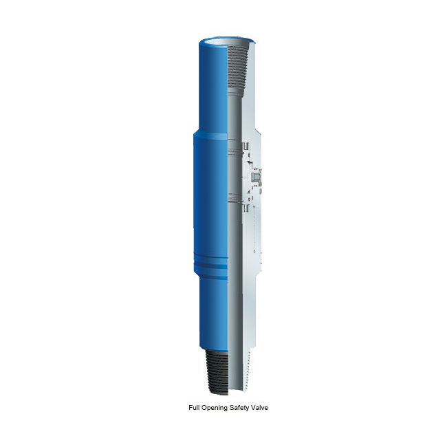
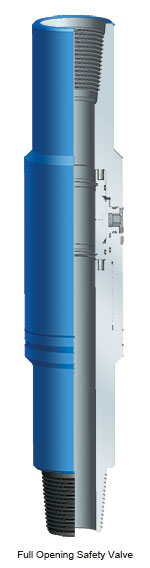
full opening safety valve brands
Distributor of hydraulic press safety, quick opening safety, rotary and safety valves. Amerigear®, Boston Gear®, Carlisle®, DeMag®, Desch® and IMI Norgren®, pneumatic, double action, quick release and flow control valves also provided. Repair and preventative maintenance services are offered. Value added services such as custom barcoding, CAD capabilities, OEM assembly, plant surveys and third party logistics are also available. Serves the metal processing, metal service center, paper mill and paper converting, canning, grinding, commercial laundry, marine, oil and gas and material handling industries. Vendor managed inventory (VMI) programs available. Kanban delivery.
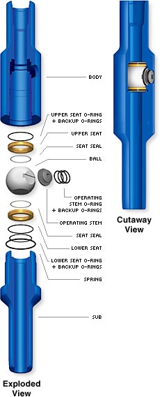
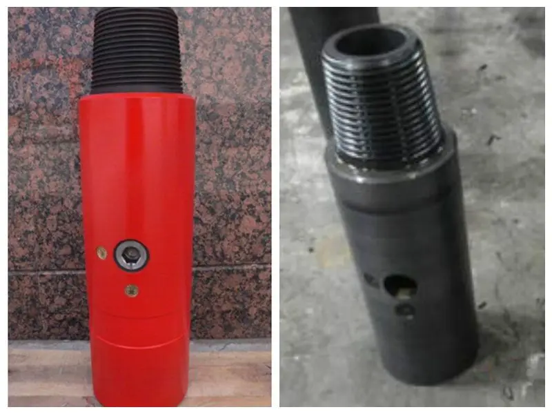
Packard Safety Valves are designed to either stab into the drill pipe or tubing at the rig floor or are used as part of the drill string to shut off a well kick. Use of these valves in the drill string enhances rig safety.
The Packard two-piece safety valve offers the convenience of a two-piece body for easy maintenance. Its full bore also allows the unrestricted flow of drilling fluid; reducing wear on critical parts while providing unrestricted access for downhole tools.
Packard International"s Safety Valves are built with enough length on each end to allow fully recutting the connections in the event of damage to the threads or shoulders where sealing takes place.
High and low pressure sealing is assured by the Teflon and metal sealing system of the ball and seats. The ball and lower seat float while the upper seat is fixed in the body. This floating/fixed design aids in low pressure sealing and enables the operator to pressure balance the valve under full rated working pressure.
... -start valve with Series MX2 air treatment units without the need for additional connection interfaces. The soft-start valve is positioned upstream of the safety valves, ...
Two hands safety valve, which allows a safety use of two hands pneumatic controls (for example two push-button 3/2 N.C. to a certain distance) excluding false signals in case of push-button ...
The SI2 safety valve prevents the allowed operating pressure from being exceeded by more than 10%. If, after opening, the adjusted response pressure falls ...
... stainless steel full-lift clean service safety valve designed to AD Merkblatt A2 and TRD 421 standards and suitable for pure steam, vapour and inert gases.
Insert style flow control valves are comprised of a precision orifice in parallel with a check valve, combined into a single component. Each is designed for easy installation into metal housings using ...
Press-in style flow control valves are comprised of a precision flow orifice in parallel with a check valve, combined into a single component. Each part is designed for easy installation into plastic ...
If you have been searching for a safety release valve that you can use to reduce short-term pressure surges successfully and diminish the effects of gas leaks, this is the product for you. With a pe of ...
... have been type tested as well. These pressure regulators have safety valves which will slam shut in the event of emergencies, such as the gas reaching too high a pressure level. The valve ...
This product has hydraulically actuated class A gas safety valves to EN 161 used for automatic shut-off. It shuts off when unstimulated for gas and air, or even biologically produced methane. It has AISi ...
The S 104 Safety Shut Off valve is mainly used to avoid any damage to components as well as to avoid too high or too low pressure in the gas train. This could cause high financial losses and/or injured ...
The S50 Safety Shut Off valve is mainly used to avoid any damage to components as well as to avoid too high or too low pressure in the gas train. This could cause high financial losses and/or injured ...
The S100 Safety Shut Off valve is mainly used to avoid any damage to components as well as to avoid too high or too low pressure in the gas train. This could cause high financial losses and/or injured ...
... Pressure Safety Valve + Rupture Disk is protected and may be utilized autonomously as essential security gadgets or in conjunction. There are 3 possible combinations. The first combinations ...
Excavator pipe-rupture valves prevent uncontrolled cylinder movement in the event that a pipe or hose bursts. The ESV valve fulfills all of the requirements of the ISO 8643 and EN 474-5 standards for ...
Material: Body- CF8M; Valve Seat- CF8M Métal Seat, PTFE Soft Seat available Orifice Size: fc"(15mm), 3/4M(20mm), l"(25mm), l1/4,’(32mm)I ltë”(40mm), ...
The Safety valves from ATOS are designed to guarantee protection for application on various devices, especially those that monitor spool position. They are also recommended for hydraulic ...
TIW is the original designer and manufacturer of ball type Safety and Kelly valves. Our strict adherence to API specifications as well as our own quality requirements ensures TIW valves are the highest quality valves in the market.
TIW Class I & Class II Kelly Valves may be utilized as a Drill Stem Safety Valve or as an Upper or Lower Kelly Cock and is designed to hold pressure from both directions.
TIW Kelly Valve Design and Quality System are certified by API.TIW Safety and Kelly Valves are also offered for H2S service, meeting all NACE standards. Standard Pressure rating is 10,000 PSI Test with higher pressure ratings available.

Curtiss-Wright"s selection of Pressure Relief Valves comes from its outstanding product brands Farris and Target Rock. We endeavor to support the whole life cycle of a facility and continuously provide custom products and technologies. Boasting a reputation for producing high quality, durable products, our collection of Pressure Relief Valves is guaranteed to provide effective and reliable pressure relief.
While some basic components and activations in relieving pressure may differ between the specific types of relief valves, each aims to be 100% effective in keeping your equipment running safely. Our current range includes numerous valve types, from flanged to spring-loaded, threaded to wireless, pilot operated, and much more.
A pressure relief valve is a type of safety valve designed to control the pressure in a vessel. It protects the system and keeps the people operating the device safely in an overpressure event or equipment failure.
A pressure relief valve is designed to withstand a maximum allowable working pressure (MAWP). Once an overpressure event occurs in the system, the pressure relief valve detects pressure beyond its design"s specified capability. The pressure relief valve would then discharge the pressurized fluid or gas to flow from an auxiliary passage out of the system.
Below is an example of one of our pilot operated pressure relief valves in action; the cutaway demonstrates when high pressure is released from the system.
Air pressure relief valves can be applied to a variety of environments and equipment. Pressure relief valves are a safety valve used to keep equipment and the operators safe too. They"re instrumental in applications where proper pressure levels are vital for correct and safe operation. Such as oil and gas, power generation like central heating systems, and multi-phase applications in refining and chemical processing.
At Curtiss-Wright, we provide a range of different pressure relief valves based on two primary operations – spring-loaded and pilot operated. Spring-loaded valves can either be conventional spring-loaded or balanced spring-loaded.
Spring-loaded valves are programmed to open and close via a spring mechanism. They open when the pressure reaches an unacceptable level to release the material inside the vessel. It closes automatically when the pressure is released, and it returns to an average operating level. Spring-loaded safety valves rely on the closing force applied by a spring onto the main seating area. They can also be controlled in numerous ways, such as a remote, control panel, and computer program.
Pilot-operated relief valves operate by combining the primary relieving device (main valve) with self-actuated auxiliary pressure relief valves, also known as the pilot control. This pilot control dictates the opening and closing of the main valve and responds to system pressure. System pressure is fed from the inlet into and through the pilot control and ultimately into the main valve"s dome. In normal operating conditions, system pressure will prevent the main valve from opening.
The valves allow media to flow from an auxiliary passage and out of the system once absolute pressure is reached, whether it is a maximum or minimum level.
When the pressure is below the maximum amount, the pressure differential is slightly positive on the piston"s dome size, which keeps the main valve in the closed position. When system pressure rises and reaches the set point, the pilot will cut off flow to the dome, causing depressurization in the piston"s dome side. The pressure differential has reversed, and the piston will rise, opening the main valve, relieving pressure.
When the process pressure decreases to a specific pressure, the pilot closes, the dome is repressurized, and the main valve closes. The main difference between spring-loaded PRVs and pilot-operated is that a pilot-operated safety valve uses pressure to keep the valve closed.
Pilot-operated relief valves are controlled by hand and are typically opened often through a wheel or similar component. The user opens the valve when the gauge signifies that the system pressure is at an unsafe level; once the valve has opened and the pressure has been released, the operator can shut it by hand again.
Increasing pressure helps to maintain the pilot"s seal. Once the setpoint has been reached, the valve opens. This reduces leakage and fugitive emissions.
At set pressure the valve snaps to full lift. This can be quite violent on large pipes with significant pressure. The pressure has to drop below the set pressure in order for the piston to reseat.
At Curtiss-Wright we also provide solutions for pressure relief valve monitoring. Historically, pressure relief valves have been difficult or impossible to monitor. Our SmartPRV features a 2600 Series pressure relief valve accessorized with a wireless position monitor that alerts plant operators during an overpressure event, including the time and duration.
There are many causes of overpressure, but the most common ones are typically blocked discharge in the system, gas blowby, and fire. Even proper inspection and maintenance will not eliminate the occurrence of leakages. An air pressure relief valve is the only way to ensure a safe environment for the device, its surroundings, and operators.
A PRV and PSV are interchangeable, but there is a difference between the two valves. A pressure release valve gradually opens when experiencing pressure, whereas a pressure safety valve opens suddenly when the pressure hits a certain level of over pressurization. Safety valves can be used manually and are typically used for a permanent shutdown. Air pressure relief valves are used for operational requirements, and they gently release the pressure before it hits the maximum high-pressure point and circulates it back into the system.
Pressure relief valves should be subject to an annual test, one per year. The operator is responsible for carrying out the test, which should be done using an air compressor. It’s imperative to ensure pressure relief valves maintain their effectiveness over time and are checked for signs of corrosion and loss of functionality. Air pressure relief valves should also be checked before their installation, after each fire event, and regularly as decided by the operators.
Direct-acting solenoid valves have a direct connection with the opening and closing armature, whereas pilot-operated valves use of the process fluid to assist in piloting the operation of the valve.
A control valve works by varying the rate of fluid passing through the valve itself. As the valve stem moves, it alters the size of the passage and increases, decreases or holds steady the flow. The opening and closing of the valve is altered whenever the controlled process parameter does not reach the set point.
Control valves are usually at floor level or easily accessible via platforms. They are also located on the same equipment or pipeline as the measurement and downstream or flow measurements.
An industrial relief valve is designed to control or limit surges of pressure in a system, most often in fluid or compressed air system valves. It does so as a form of protection for the system and defending against instrument or equipment failure. They are usually present in clean water industries.
A PRV is often referred to as a pressure relief valve, which is also known as a PSV or pressure safety valve. They are used interchangeably throughout the industry depending on company standards.
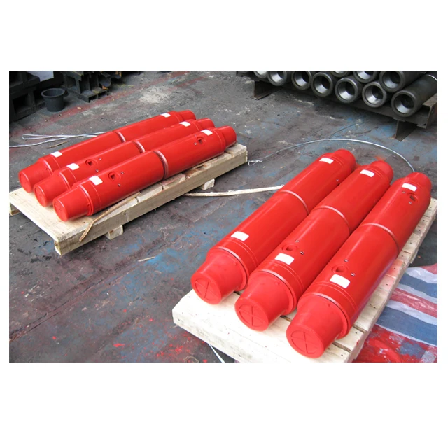
Alibaba.com offers 37 full opening safety valve for drilling products. About 75% % of these are mining machine parts, 10%% are valves, and 8%% are other oil field equipments.
A wide variety of full opening safety valve for drilling options are available to you, such as energy & mining, construction works and manufacturing plant.You can also choose from 1.5 years, 6 months and 3 years full opening safety valve for drilling,As well as from bearing, {2}, and {3}. and whether full opening safety valve for drilling is russia, kazakhstan, or egypt.

FULL OPENING SAFETY VALVE, OD: 3.1/2", MIN ID: 2-1/4", WORKING PRESSURE 5000 PSI, CONNECTION 3.1/2" IF , COMPLETE WITH WRENCH, WITHOUT HYDROGEN SULFIDE
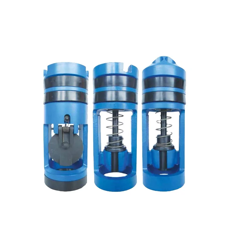
The M&M International CANISTER GUARD® encapsulates its internal spring loading within the canister itself, which is a significant feature that cannot be overstated. During disassembly of one-piece valves made by other manufacturers, the internal spring must be compressed prior to removal of the locking mechanism. Considering the application, it is typical for mud, cement, debris, and/or corrosion to accumulate in this area. This makes it difficult or even impossible to compress the spring enough to remove the locking mechanism from valves of this kind, even when using the special tools required by the competitor manufacturer. These and other issues can make field dressing impractical and shop dressing a much longer and more expensive process than necessary. M&M International’s CANISTER GUARD® technology completely eliminates these issues, saving both time and money.
M&M International’s CANISTER GUARD® reduces the need for customer locations to keep large spare valve parts inventories on hand. In most cases, CANISTER GUARD® valves utilize identical parts within each size range. This low inventory ability allows a customer to operate with one spare canister and one or two spare operating stems in inventory, if necessary.
There is a wide range of safety valves available to meet the many different applications and performance criteria demanded by different industries. Furthermore, national standards define many varying types of safety valve.
The ASME standard I and ASME standard VIII for boiler and pressure vessel applications and the ASME/ANSI PTC 25.3 standard for safety valves and relief valves provide the following definition. These standards set performance characteristics as well as defining the different types of safety valves that are used:
ASME I valve - A safety relief valve conforming to the requirements of Section I of the ASME pressure vessel code for boiler applications which will open within 3% overpressure and close within 4%. It will usually feature two blowdown rings, and is identified by a National Board ‘V’ stamp.
ASME VIII valve- A safety relief valve conforming to the requirements of Section VIII of the ASME pressure vessel code for pressure vessel applications which will open within 10% overpressure and close within 7%. Identified by a National Board ‘UV’ stamp.
Full bore safety valve - A safety valve having no protrusions in the bore, and wherein the valve lifts to an extent sufficient for the minimum area at any section, at or below the seat, to become the controlling orifice.
Conventional safety relief valve -The spring housing is vented to the discharge side, hence operational characteristics are directly affected by changes in the backpressure to the valve.
Balanced safety relief valve -A balanced valve incorporates a means of minimising the effect of backpressure on the operational characteristics of the valve.
Pilot operated pressure relief valve -The major relieving device is combined with, and is controlled by, a self-actuated auxiliary pressure relief device.
Power-actuated safety relief valve - A pressure relief valve in which the major pressure relieving device is combined with, and controlled by, a device requiring an external source of energy.
Standard safety valve - A valve which, following opening, reaches the degree of lift necessary for the mass flowrate to be discharged within a pressure rise of not more than 10%. (The valve is characterised by a pop type action and is sometimes known as high lift).
Full lift (Vollhub) safety valve -A safety valve which, after commencement of lift, opens rapidly within a 5% pressure rise up to the full lift as limited by the design. The amount of lift up to the rapid opening (proportional range) shall not be more than 20%.
Direct loaded safety valve -A safety valve in which the opening force underneath the valve disc is opposed by a closing force such as a spring or a weight.
Proportional safety valve - A safety valve which opens more or less steadily in relation to the increase in pressure. Sudden opening within a 10% lift range will not occur without pressure increase. Following opening within a pressure of not more than 10%, these safety valves achieve the lift necessary for the mass flow to be discharged.
Diaphragm safety valve -A direct loaded safety valve wherein linear moving and rotating elements and springs are protected against the effects of the fluid by a diaphragm
Bellows safety valve - A direct loaded safety valve wherein sliding and (partially or fully) rotating elements and springs are protected against the effects of the fluids by a bellows. The bellows may be of such a design that it compensates for influences of backpressure.
Controlled safety valve - Consists of a main valve and a control device. It also includes direct acting safety valves with supplementary loading in which, until the set pressure is reached, an additional force increases the closing force.
Safety valve - A safety valve which automatically, without the assistance of any energy other than that of the fluid concerned, discharges a quantity of the fluid so as to prevent a predetermined safe pressure being exceeded, and which is designed to re-close and prevent further flow of fluid after normal pressure conditions of service have been restored. Note; the valve can be characterised either by pop action (rapid opening) or by opening in proportion (not necessarily linear) to the increase in pressure over the set pressure.
Direct loaded safety valve -A safety valve in which the loading due to the fluid pressure underneath the valve disc is opposed only by a direct mechanical loading device such as a weight, lever and weight, or a spring.
Assisted safety valve -A safety valve which by means of a powered assistance mechanism, may additionally be lifted at a pressure lower than the set pressure and will, even in the event of a failure of the assistance mechanism, comply with all the requirements for safety valves given in the standard.
Supplementary loaded safety valve - A safety valve that has, until the pressure at the inlet to the safety valve reaches the set pressure, an additional force, which increases the sealing force.
Note; this additional force (supplementary load), which may be provided by means of an extraneous power source, is reliably released when the pressure at the inlet of the safety valve reaches the set pressure. The amount of supplementary loading is so arranged that if such supplementary loading is not released, the safety valve will attain its certified discharge capacity at a pressure not greater than 1.1 times the maximum allowable pressure of the equipment to be protected.
Pilot operated safety valve -A safety valve, the operation of which is initiated and controlled by the fluid discharged from a pilot valve, which is itself, a direct loaded safety valve subject to the requirement of the standard.
The common characteristic shared between the definitions of conventional safety valves in the different standards, is that their operational characteristics are affected by any backpressure in the discharge system. It is important to note that the total backpressure is generated from two components; superimposed backpressure and the built-up backpressure:
Subsequently, in a conventional safety valve, only the superimposed backpressure will affect the opening characteristic and set value, but the combined backpressure will alter the blowdown characteristic and re-seat value.
The ASME/ANSI standard makes the further classification that conventional valves have a spring housing that is vented to the discharge side of the valve. If the spring housing is vented to the atmosphere, any superimposed backpressure will still affect the operational characteristics. Thiscan be seen from Figure 9.2.1, which shows schematic diagrams of valves whose spring housings are vented to the discharge side of the valve and to the atmosphere.
By considering the forces acting on the disc (with area AD), it can be seen that the required opening force (equivalent to the product of inlet pressure (PV) and the nozzle area (AN)) is the sum of the spring force (FS) and the force due to the backpressure (PB) acting on the top and bottom of the disc. In the case of a spring housing vented to the discharge side of the valve (an ASME conventional safety relief valve, see Figure 9.2.1 (a)), the required opening force is:
In both cases, if a significant superimposed backpressure exists, its effects on the set pressure need to be considered when designing a safety valve system.
Once the valve starts to open, the effects of built-up backpressure also have to be taken into account. For a conventional safety valve with the spring housing vented to the discharge side of the valve, see Figure 9.2.1 (a), the effect of built-up backpressure can be determined by considering Equation 9.2.1 and by noting that once the valve starts to open, the inlet pressure is the sum of the set pressure, PS, and the overpressure, PO.
Balanced safety valves are those that incorporate a means of eliminating the effects of backpressure. There are two basic designs that can be used to achieve this:
Although there are several variations of the piston valve, they generally consist of a piston type disc whose movement is constrained by a vented guide. The area of the top face of the piston, AP, and the nozzle seat area, AN, are designed to be equal. This means that the effective area of both the top and bottom surfaces of the disc exposed to the backpressure are equal, and therefore any additional forces are balanced. In addition, the spring bonnet is vented such that the top face of the piston is subjected to atmospheric pressure, as shown in Figure 9.2.2.
The bellows arrangement prevents backpressure acting on the upper side of the disc within the area of the bellows. The disc area extending beyond the bellows and the opposing disc area are equal, and so the forces acting on the disc are balanced, and the backpressure has little effect on the valve opening pressure.
Bellows failure is an important concern when using a bellows balanced safety valve, as this may affect the set pressure and capacity of the valve. It is important, therefore, that there is some mechanism for detecting any uncharacteristic fluid flow through the bellows vents. In addition, some bellows balanced safety valves include an auxiliary piston that is used to overcome the effects of backpressure in the case of bellows failure. This type of safety valve is usually only used on critical applications in the oil and petrochemical industries.
Since balanced pressure relief valves are typically more expensive than their unbalanced counterparts, they are commonly only used where high pressure manifolds are unavoidable, or in critical applications where a very precise set pressure or blowdown is required.
This type of safety valve uses the flowing medium itself, through a pilot valve, to apply the closing force on the safety valve disc. The pilot valve is itself a small safety valve.
The diaphragm type is typically only available for low pressure applications and it produces a proportional type action, characteristic of relief valves used in liquid systems. They are therefore of little use in steam systems, consequently, they will not be considered in this text.
The piston type valve consists of a main valve, which uses a piston shaped closing device (or obturator), and an external pilot valve. Figure 9.2.4 shows a diagram of a typical piston type, pilot operated safety valve.
The piston and seating arrangement incorporated in the main valve is designed so that the bottom area of the piston, exposed to the inlet fluid, is less than the area of the top of the piston. As both ends of the piston are exposed to the fluid at the same pressure, this means that under normal system operating conditions, the closing force, resulting from the larger top area, is greater than the inlet force. The resultant downward force therefore holds the piston firmly on its seat.
If the inlet pressure were to rise, the net closing force on the piston also increases, ensuring that a tight shut-off is continually maintained. However, when the inlet pressure reaches the set pressure, the pilot valve will pop open to release the fluid pressure above the piston. With much less fluid pressure acting on the upper surface of the piston, the inlet pressure generates a net upwards force and the piston will leave its seat. This causes the main valve to pop open, allowing the process fluid to be discharged.
When the inlet pressure has been sufficiently reduced, the pilot valve will reclose, preventing the further release of fluid from the top of the piston, thereby re-establishing the net downward force, and causing the piston to reseat.
Pilot operated safety valves offer good overpressure and blowdown performance (a blowdown of 2% is attainable). For this reason, they are used where a narrow margin is required between the set pressure and the system operating pressure. Pilot operated valves are also available in much larger sizes, making them the preferred type of safety valve for larger capacities.
One of the main concerns with pilot operated safety valves is that the small bore, pilot connecting pipes are susceptible to blockage by foreign matter, or due to the collection of condensate in these pipes. This can lead to the failure of the valve, either in the open or closed position, depending on where the blockage occurs.
The terms full lift, high lift and low lift refer to the amount of travel the disc undergoes as it moves from its closed position to the position required to produce the certified discharge capacity, and how this affects the discharge capacity of the valve.
A full lift safety valve is one in which the disc lifts sufficiently, so that the curtain area no longer influences the discharge area. The discharge area, and therefore the capacity of the valve are subsequently determined by the bore area. This occurs when the disc lifts a distance of at least a quarter of the bore diameter. A full lift conventional safety valve is often the best choice for general steam applications.
The disc of a high lift safety valve lifts a distance of at least 1/12th of the bore diameter. This means that the curtain area, and ultimately the position of the disc, determines the discharge area. The discharge capacities of high lift valves tend to be significantly lower than those of full lift valves, and for a given discharge capacity, it is usually possible to select a full lift valve that has a nominal size several times smaller than a corresponding high lift valve, which usually incurs cost advantages.Furthermore, high lift valves tend to be used on compressible fluids where their action is more proportional.
In low lift valves, the disc only lifts a distance of 1/24th of the bore diameter. The discharge area is determined entirely by the position of the disc, and since the disc only lifts a small amount, the capacities tend to be much lower than those of full or high lift valves.
Except when safety valves are discharging, the only parts that are wetted by the process fluid are the inlet tract (nozzle) and the disc. Since safety valves operate infrequently under normal conditions, all other components can be manufactured from standard materials for most applications. There are however several exceptions, in which case, special materials have to be used, these include:
Cast steel -Commonly used on higher pressure valves (up to 40 bar g). Process type valves are usually made from a cast steel body with an austenitic full nozzle type construction.
For all safety valves, it is important that moving parts, particularly the spindle and guides are made from materials that will not easily degrade or corrode. As seats and discs are constantly in contact with the process fluid, they must be able to resist the effects of erosion and corrosion.
The spring is a critical element of the safety valve and must provide reliable performance within the required parameters. Standard safety valves will typically use carbon steel for moderate temperatures. Tungsten steel is used for higher temperature, non-corrosive applications, and stainless steel is used for corrosive or clean steam duty. For sour gas and high temperature applications, often special materials such as monel, hastelloy and ‘inconel’ are used.
Standard safety valves are generally fitted with an easing lever, which enables the valve to be lifted manually in order to ensure that it is operational at pressures in excess of 75% of set pressure. This is usually done as part of routine safety checks, or during maintenance to prevent seizing. The fitting of a lever is usually a requirement of national standards and insurance companies for steam and hot water applications. For example, the ASME Boiler and Pressure Vessel Code states that pressure relief valves must be fitted with a lever if they are to be used on air, water over 60°C, and steam.
A test gag (Figure 9.2.7) may be used to prevent the valve from opening at the set pressure during hydraulic testing when commissioning a system. Once tested, the gag screw is removed and replaced with a short blanking plug before the valve is placed in service.
The amount of fluid depends on the particular design of safety valve. If emission of this fluid into the atmosphere is acceptable, the spring housing may be vented to the atmosphere – an open bonnet. This is usually advantageous when the safety valve is used on high temperature fluids or for boiler applications as, otherwise, high temperatures can relax the spring, altering the set pressure of the valve. However, using an open bonnet exposes the valve spring and internals to environmental conditions, which can lead to damage and corrosion of the spring.
When the fluid must be completely contained by the safety valve (and the discharge system), it is necessary to use a closed bonnet, which is not vented to the atmosphere. This type of spring enclosure is almost universally used for small screwed valves and, it is becoming increasingly common on many valve ranges since, particularly on steam, discharge of the fluid could be hazardous to personnel.
Some safety valves, most commonly those used for water applications, incorporate a flexible diaphragm or bellows to isolate the safety valve spring and upper chamber from the process fluid, (see Figure 9.2.9).

Consolidated boasts 140+ years of dedicated Pressure Relief Valve (PRV) Engineering and Manufacturing expertise. We know overpressure protection! With more than 10 major first-to-market products and features, Consolidated continues to deliver innovative technical solutions to the world"s most challenging overpressure protection applications. When combined with the expertise and full-scale service of the Green Tag Center (GTC) Network, Consolidated is able to provide a comprehensive approach to Valve Lifecycle Management (VLM) that is second to none.
Comprehensive Valve Lifecycle Management (VLM) enabled by state-of-the-art tools and delivered by the unparalleled Consolidated Green Tag Center (GTC) Network, Consolidated supports our product throughout the entire lifecycle.

Two-adjusting-ring design of the Consolidated Type 1541 and 1543 safety valves allows for sharp opening action and full lift at three percent overpressure. The self-aligning spring washers help increase repeatability and the valve"s life span.
Suitable for steam and other compressible fluid applications. the Consolidated Type 1541 and 1543 safety valves are ASME Section I and VIII approved. They are most commonly used in pharmaceutical, dying and process plants.
The Consolidated Type 1541 and 1543 safety valves are configured for steam and other compressible fluids. Compression media is limited to non-toxic, non-flammable, non-corrosive service. They are most commonly used in pharmaceutical and process plants.

Safety valves or pressure relief valves are pressure regulating devices that are responsible for expelling excess pressure from the system when the maximum pressure levels for which they have been designed are exceeded, usually due to a
Safety valves perform their function when the pressure of the system where the fluid is contained, becomes higher than the maximum set pressure of the valve previously adjusted. When the system pressure is higher than the valve’s set
pressure, this opens, releasing the excess pressure to the atmosphere or to containment tanks, depending on the toxicity of the fluid. After releasing the excess, the valve closes again and the system pressure returns to normal.
To ensure total safety of personnel and installation, make sure that the valves have passed all safety tests and meet the requirements of the system where they are to be installed. All our valves are supplied with certificates of materials, cas-
What is the difference between the instantaneous full opening safety valve AIT (PSV) and the normal opening relief valve AN or progressive opening relief valve AP (PRV)?
The Pressure Safety Valve (PSV) opens instantaneously and fully upon reaching the set pressure for which it is designed, expelling the excess pressure from the system immediately. They are optimised for use with steam or gases.
In contrast, the normally or progressively opening Pressure Relief Valve (PRV) opens gradually as the system pressure rises above the set pressure of the valve above its setting. They are optimised to work with liquids.
At VYC Industrial we are specialists in the design and manufacture of all types of safety valves. We have a wide range of safety valves to cover all the needs of the sector.
The Mod. 496 EN safety valve works as an automatic pressure releasing regulator activated by the static pressure existing at the entrance to the valve and is characterized by its ability to open instantly and totally.
The Mod. 495 EN pressure relief valve works as an automatic pressure releasing regulator activated by the static pressure existing at the entrance to the valve and is characterized by its ability to open instantly and totally.
The relief valve works as an automatic pressure releasing regulator activated by the static pressure existing at the entrance to the valve and is characterized by its ability to open instantly and totally.
The valve works as an automatic pressure releasing regulator activated by the static pressure existing at the entrance to the valve and is characterized by its ability to open instantly and totally.
The valve works as an automatic pressure releasing regulator activated by the static pressure existing at the entrance to the valve and is characterized by its ability to open instantly and totally.
The valve works as an automatic pressure releasing regulator activated by the static pressure existing at the entrance to the valve and is characterized by its ability to open instantly and totally.
The valve works as an automatic pressure releasing regulator activated by the static pressure existing at the entrance to the valve and is characterized by its ability to open instantly and totally.
The valve works as an automatic pressure releasing regulator activated by the static pressure existing at the entrance to the valve and is characterized by its ability to open instantly and totally.
The valve works as an automatic pressure releasing regulator activated by the static pressure existing at the entrance to the valve and is characterized by its ability to open, at the fi rst proportional to the pressure increase, and after instantly and totally.
The valve works as an automatic pressure releasing regulator activated by the static pressure existing at the entrance to the valve and is characterized by its ability to open, at the fi rst proportional to the pressure increase, and after instantly and totally.
The valve works as an automatic pressure releasing regulator activated by the static pressure existing at the entrance to the valve and is characterized by its ability to open, at the fi rst proportional to the pressure increase, and after instantly and totally.
The valve works as an automatic pressure releasing regulator activated by the static pressure existing at the entrance to the valve and is characterized by its ability to open proportional to the pressure increase.
The valve works as an automatic pressure releasing regulator activated by the static pressure existing at the entrance to the valve and is characterized by its ability to open proportional to the pressure increase.
The valve works as an automatic pressure releasing regulator activated by the static pressure existing at the entrance to the valve and is characterized by its ability to open instantly and totally.
The valve works as an automatic pressure releasing regulator activated by the static pressure existing at the entrance to the valve and is characterized by its ability to open instantly and totally.
The valve works as an automatic pressure releasing regulator activated by the static pressure existing at the entrance to the valve and is characterized by its ability to open instantly and totally.
The valve works as an automatic pressure releasing regulator activated by the static pressure existing at the entrance to the valve and is characterized by its ability to open instantly and totally.
The valve works as an automatic pressure releasing regulator activated by the static pressure existing at the entrance to the valve and is characterized by its ability to open instantly and totally.
They are used in places such as power, chemical and petrochemical plants to discharge safety valves, control valves, etc. in pressure lines and equipment that convey compressible substances such as steam, air, carbon dioxide, helium, methane, nitrogen, oxygen and other gases.
Test bench for regular inspections and setting and resetting safety valves. Ideal for distributors, maintenance companies or with in-house maintenance. It allows safety valves to be adjusted, tested and/or checked to the test pressure (setting) Pe wile cold (simulating service conditions), matching the opening pressure Ps and the closing pressure Pc, in accordance with the standard regulations.
Controlled safety pressure relief system CSPRS valves are mainly used where conventional direct-loaded spring action valves cannot guarantee the opening and closing margins that certain specifi c conditions of service demand.
The objective is to help the closure by means of pressure so that the valve remains completely watertight until reaching the set pressure and/or to activate the opening with pressure.
Increase the operating pressure of the system up to 99.9% of the set pressure.The control safety pressure relief system CSPRS device can be used with any safety valve available in the market and in particular, with models VYC Mod. 485, 486, 494, 495 and 496.

The IBOP, also called Gray Valve or BVR, is a back pressure valve used in the drill string to prevent the well from flowing uncontrollably up the drill string. It is generally used in 2 ways:
The RDCV, also called Dart Valve or a Back-Pressure Valve, controls backflow through the drill pipe during a kick or when tripping pipe into the hole against pressure. Check-valve compatibility should be checked with Kelly Cock free passage.

Of all the challenges you face keeping your customers’ plants operating at full capacity, safety and relief valves shouldn’t be one of them. NASVI’s job is to give you the confidence that your valve supply chain is rock solid regardless the pressure it’s under.


 8613371530291