
full opening safety valve made in china

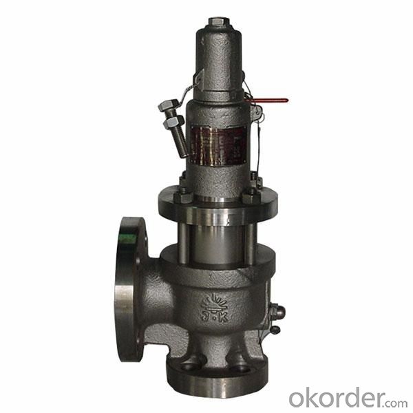
Flange Full Lift Safety Valve refers to a kind of safety valve with relatively small opening height and discharge capacity of valve disc. The sealing surface of the valve disc has two types: flat surf...
Thread Full Lift Safety Valve refers to a kind of safety valve with relatively small opening height and discharge capacity of valve disc. The sealing surface of the valve disc has two types: flat surf...
Flange Low Lift Safety Valve refers to a kind of safety valve with relatively small opening height and discharge capacity of valve disc. The sealing surface of the valve disc has two types: flat surfa...
Thread Low Lift Safety Valve refers to a kind of safety valve with relatively small opening height and discharge capacity of valve disc. The sealing surface of the valve disc has two types: flat surfa...
PTFE Lined Safety Valve is a safety valve successfully developed by our company in the field of chemical industry based on advanced technology at home and abroad. The valve is an automatic pressure re...
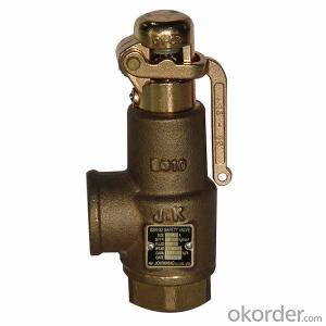
The KOSEN Bronze Safety Valve Copper safety valve is a kind of automatic control and protection valve. He does not rely on any external force, but uses the force of the medium itself to discharge a ce...

As soon as mankind was able to boil water to create steam, the necessity of the safety device became evident. As long as 2000 years ago, the Chinese were using cauldrons with hinged lids to allow (relatively) safer production of steam. At the beginning of the 14th century, chemists used conical plugs and later, compressed springs to act as safety devices on pressurised vessels.
Early in the 19th century, boiler explosions on ships and locomotives frequently resulted from faulty safety devices, which led to the development of the first safety relief valves.
In 1848, Charles Retchie invented the accumulation chamber, which increases the compression surface within the safety valve allowing it to open rapidly within a narrow overpressure margin.
Today, most steam users are compelled by local health and safety regulations to ensure that their plant and processes incorporate safety devices and precautions, which ensure that dangerous conditions are prevented.
The principle type of device used to prevent overpressure in plant is the safety or safety relief valve. The safety valve operates by releasing a volume of fluid from within the plant when a predetermined maximum pressure is reached, thereby reducing the excess pressure in a safe manner. As the safety valve may be the only remaining device to prevent catastrophic failure under overpressure conditions, it is important that any such device is capable of operating at all times and under all possible conditions.
Safety valves should be installed wherever the maximum allowable working pressure (MAWP) of a system or pressure-containing vessel is likely to be exceeded. In steam systems, safety valves are typically used for boiler overpressure protection and other applications such as downstream of pressure reducing controls. Although their primary role is for safety, safety valves are also used in process operations to prevent product damage due to excess pressure. Pressure excess can be generated in a number of different situations, including:
The terms ‘safety valve’ and ‘safety relief valve’ are generic terms to describe many varieties of pressure relief devices that are designed to prevent excessive internal fluid pressure build-up. A wide range of different valves is available for many different applications and performance criteria.
In most national standards, specific definitions are given for the terms associated with safety and safety relief valves. There are several notable differences between the terminology used in the USA and Europe. One of the most important differences is that a valve referred to as a ‘safety valve’ in Europe is referred to as a ‘safety relief valve’ or ‘pressure relief valve’ in the USA. In addition, the term ‘safety valve’ in the USA generally refers specifically to the full-lift type of safety valve used in Europe.
Pressure relief valve- A spring-loaded pressure relief valve which is designed to open to relieve excess pressure and to reclose and prevent the further flow of fluid after normal conditions have been restored. It is characterised by a rapid-opening ‘pop’ action or by opening in a manner generally proportional to the increase in pressure over the opening pressure. It may be used for either compressible or incompressible fluids, depending on design, adjustment, or application.
Safety valves are primarily used with compressible gases and in particular for steam and air services. However, they can also be used for process type applications where they may be needed to protect the plant or to prevent spoilage of the product being processed.
Relief valve - A pressure relief device actuated by inlet static pressure having a gradual lift generally proportional to the increase in pressure over opening pressure.
Relief valves are commonly used in liquid systems, especially for lower capacities and thermal expansion duty. They can also be used on pumped systems as pressure overspill devices.
Safety relief valve - A pressure relief valve characterised by rapid opening or pop action, or by opening in proportion to the increase in pressure over the opening pressure, depending on the application, and which may be used either for liquid or compressible fluid.
In general, the safety relief valve will perform as a safety valve when used in a compressible gas system, but it will open in proportion to the overpressure when used in liquid systems, as would a relief valve.
Safety valve- A valve which automatically, without the assistance of any energy other than that of the fluid concerned, discharges a quantity of the fluid so as to prevent a predetermined safe pressure being exceeded, and which is designed to re-close and prevent further flow of fluid after normal pressure conditions of service have been restored.

We always stick to the principle "Quality First, Prestige Supreme". We are fully committed to providing our clients with competitively priced quality products, prompt delivery and professional service for Gas Safety Valve, Pipe Clamp Fittings, Oil Tanker Valve, 2 Pipe Clamp,Stainless Steel Boat Propeller. For more information, please send email to us. We are looking forwards the opportunity to service you. The product will supply to all over the world, such as Europe, America, Australia,Roman, Turkey,Japan, European.Aiming to grow to be by far the most experienced supplier within this sector in Uganda, we keep researching on the creating procedure and raising the high quality of our principal merchandise. Till now, the merchandise list has been updated on a regular basis and attracted customers from around the globe. In depth data can be obtained in our web page and you"ll be served with good quality consultant service by our after-sale team. They"re about to make it possible for you to get complete acknowledge about our things and make a satisfied negotiation. Small business check out to our factory in Uganda can also be welcome at any time. Hope to obtain your inquiries to get a happy co-operation.

There are various safety valves available to meet various applications and performance criteria demanded by various industries. Furthermore, national standards determine many types of varied safety valves.
Standard ASME I and ASME VIII standards for boiler applications and vessels and ASME / ANSI PTC 25.3 standards for safety valves and relief valves provide the following definition. These standards set performance characteristics and define various types of safety valves used:
ASME I valve - A safety relief valve conforming to the requirements of Section I of the ASME pressure vessel code for boiler applications which will open within 3% overpressure and close within 4%. It will usually feature two blowdown rings and is identified by a National Board ‘V’ stamp.
ASME VIII valve - A safety relief valve conforming to the requirements of Section VIII of the ASME pressure vessel code for pressure vessel applications which will open within 10% overpressure and close within 7%. Identified by a National Board ‘UV’ stamp.
Full bore safety valve - A safety valve having no protrusions in the bore, and wherein the valve lifts to an extent sufficient for the minimum area at any section, at or below the seat, to become the controlling orifice.
Conventional safety relief valve - The spring housing is vented to the discharge side, hence operational characteristics are directly affected by changes in the backpressure to the valve.
Balanced safety relief valve - A balanced valve incorporates a means of minimizing the effect of backpressure on the operational characteristics of the valve.
Pilot operated pressure relief valve - The major relieving device is combined with, and is controlled by, a self-actuated auxiliary pressure relief device.
Power-actuated safety relief valve - A pressure relief valve in which the major pressure-relieving device is combined with, and controlled by, a device requiring an external source of energy.
Standard safety valve - A valve which, following the opening, reaches the degree of lift necessary for the mass flowrate to be discharged within a pressure rise of not more than 10%. (The valve is characterized by a pop-type action and is sometimes known as high lift).
Full lift (Vollhub) safety valve - A safety valve which, after commencement of lift, opens rapidly within a 5% pressure rise up to the full lift as limited by the design. The amount of lift up to the rapid opening (proportional range) shall not be more than 20%.
Directly loaded safety valve - A safety valve in which the opening force underneath the valve disc is opposed by a closing force such as a spring or a weight.
Proportional safety valve - A safety valve that opens more or less steadily in relation to the increase in pressure. Sudden opening within a 10% lift range will not occur without a pressure increase. Following opening within a pressure of not more than 10%, these safety valves achieve the lift necessary for the mass flow to be discharged.
Diaphragm safety valve - A directly loaded safety valve wherein linear moving and rotating elements and springs are protected against the effects of the fluid by a diaphragm
Bellows safety valve - A directly loaded safety valve wherein sliding and (partially or fully) rotating elements and springs are protected against the effects of the fluids by a bellows. The bellows may be of such a design that it compensates for influences of backpressure.
Controlled safety valve- Consists of the main valve and a control device. It also includes direct acting safety valves with supplementary loading in which, until the set pressure is reached, an additional force increases the closing force.
Safety valve - A safety valve which automatically, without the assistance of any energy other than that of the fluid concerned, discharges a quantity of the fluid so as to prevent a predetermined safe pressure from being exceeded, and which is designed to re-close and prevent further flow of fluid after normal pressure conditions of service have been restored. Note; the valve can be characterized either by pop action (rapid opening) or by opening in proportion (not necessarily linear) to the increase in pressure over the set pressure.
Directly loaded safety valve - A safety valve in which the loading due to the fluid pressure underneath the valve disc is opposed only by a direct mechanical loading device such as weight, lever, and weight, or a spring.
Assisted safety valve - A safety valve which by means of a powered assistance mechanism, may additionally be lifted at a pressure lower than the set pressure and will, even in the event of a failure of the assistance mechanism, comply with all the requirements for safety valves given in the standard.
Supplementary loaded safety valve - A safety valve that has, until the pressure at the inlet to the safety valve reaches the set pressure, an additional force, which increases the sealing force.
Notes; This additional strength (additional burden), which can be provided through foreign resources, is reliably released when the pressure on the safety valve inlet reaches the specified pressure. The amount of additional loading is very regulated that if the additional loading is not released, the safety valve will reach its certified discharge capacity at a pressure which is no greater than 1.1 times the maximum pressure that is permitted to be protected.
Pilot operated safety valve - A safety valve, the operation of which is initiated and controlled by the fluid discharged from a pilot valve, which is itself, a directly loaded safety valve subject to the requirement of the standard.
The common characteristic shared between the definitions of conventional safety valves in the different standards, is that their operational characteristics are affected by any backpressure in the discharge system. It is important to note that the total backpressure is generated from two components; superimposed backpressure and the built-up backpressure:
Subsequently, in a conventional safety valve, only the superimposed backpressure will affect the opening characteristic and set value, but the combined backpressure will alter the blowdown characteristic and re-seat value.
Once the valve starts to open, the effects of built-up backpressure also have to be taken into account. For a conventional safety valve with the spring housing vented to the discharge side of the valve.
Therefore, if the back pressure is greater than the overpressure, the valve will tend to close, reducing the flow. This can lead to instability within the system and can result in flutter or chatter of the valve.
In general, if conventional safety valves are used in applications, where there is excessive built-up backpressure, they will not perform as expected. According to the API 520 Recommended Practice Guidelines:
A conventional pressure relief valve should typically not be used when the built-up backpressure is greater than 10% of the set pressure at 10% overpressure. A higher maximum allowable built-up backpressure may be used for overpressure greater than 10%.
The European Standard EN ISO 4126, however, states that the built-up backpressure should be limited to 10% of the set pressure when the valve is discharging at the certified capacity.
For the majority of steam applications, the back pressure can be maintained within these limits by carefully sizing any discharge pipes. This will be discussed in Module 9.4. If, however, it is not feasible to reduce the backpressure, then it may be necessary to use a balanced safety valve.
Balanced safety valves are those that incorporate a means of eliminating the effects of backpressure. There are two basic designs that can be used to achieve this:
The bellows arrangement prevents back pressure acting on the upper side of the disc within the area of the bellows. The disc area extending beyond the bellows and the opposing disc area are equal, and so the forces acting on the disc are balanced, and the backpressure has little effect on the valve opening pressure.
Bellows failure is an important concern when using a bellows balanced safety valve, as this may affect the set pressure and capacity of the valve. It is important, therefore, that there is some mechanism for detecting any uncharacteristic fluid flow through the bellows vents. In addition, some bellows balanced safety valves include an auxiliary piston that is used to overcome the effects of backpressure in the case of bellows failure. This type of safety valve is usually only used on critical applications in the oil and petrochemical industries.
Since balanced pressure relief valves are typically more expensive than their unbalanced counterparts, they are commonly only used where high-pressure manifolds are unavoidable, or in critical applications where a very precise set pressure or blowdown is required.
This type of safety valve uses the flowing medium itself, through a pilot valve, to apply the closing force on the safety valve disc. The pilot valve is itself a small safety valve.
The diaphragm type is typically only available for low-pressure applications and it produces a proportional type action, characteristic of relief valves used in liquid systems. They are therefore of little use in steam systems, consequently, they will not be considered in this text.
The piston-type valve consists of the main valve, which uses a piston-shaped closing device (or obturator), and an external pilot valve. Below photo shows a diagram of a typical piston type, pilot-operated safety valve.
The piston and seating arrangement incorporated in the main valve is designed so that the bottom area of the piston, exposed to the inlet fluid, is less than the area of the top of the piston. As both ends of the piston are exposed to the fluid at the same pressure, this means that under normal system operating conditions, the closing force, resulting from the larger top area, is greater than the inlet force. The resultant downward force therefore holds the piston firmly on its seat.
If the inlet pressure were to rise, the net closing force on the piston also increases, ensuring that a tight shut-off is continually maintained. However, when the inlet pressure reaches the set pressure, the pilot valve will pop open to release the fluid pressure above the piston. With much less fluid pressure acting on the upper surface of the piston, the inlet pressure generates a net upwards force and the piston will leave its seat. This causes the main valve to pop open, allowing the process fluid to be discharged.
When the inlet pressure has been sufficiently reduced, the pilot valve will reclose, preventing the further release of fluid from the top of the piston, thereby re-establishing the net downward force, and causing the piston to reseat.
Pilot operated safety valves offer good overpressure and blowdown performance (a blowdown of 2% is attainable). For this reason, they are used where a narrow margin is required between the set pressure and the system operating pressure. Pilot operated valves are also available in much larger sizes, making them the preferred type of safety valve for larger capacities.
One of the main concerns with pilot operated safety valves is that the small bore, pilot connecting pipes are susceptible to blockage by foreign matter, or due to the collection of condensate in these pipes. This can lead to the failure of the valve, either in the open or closed position, depending on where the blockage occurs.
The terms full lift, high lift and low lift refer to the amount of travel the disc undergoes as it moves from its closed position to the position required to produce the certified discharge capacity, and how this affects the discharge capacity of the valve.
A full lift safety valve is one in which the disc lifts sufficiently, so that the curtain area no longer influences the discharge area. The discharge area, and therefore the capacity of the valve are subsequently determined by the bore area. This occurs when the disc lifts a distance of at least a quarter of the bore diameter. A full lift conventional safety valve is often the best choice for general steam applications.
The disc of a high lift safety valve lifts a distance of at least 1/12th of the bore diameter. This means that the curtain area, and ultimately the position of the disc, determines the discharge area. The discharge capacities of high lift valves tend to be significantly lower than those of full lift valves, and for a given discharge capacity, it is usually possible to select a full lift valve that has a nominal size several times smaller than a corresponding high lift valve, which usually incurs cost advantages.Furthermore, high lift valves tend to be used on compressible fluids where their action is more proportional.
In low lift valves, the disc only lifts a distance of 1/24th of the bore diameter. The discharge area is determined entirely by the position of the disc, and since the disc only lifts a small amount, the capacities tend to be much lower than those of full or high lift valves.
Except when safety valves are discharging, the only parts that are wetted by the process fluid are the inlet tract (nozzle) and the disc. Since safety valves operate infrequently under normal conditions, all other components can be manufactured from standard materials for most applications. There are however several exceptions, in which case, special materials have to be used, these include:
Cast steel - Commonly used on higher pressure valves (up to 40 bar g). Process type valves are usually made from a cast steel body with an austenitic full nozzle type construction.
For all safety valves, it is important that moving parts, particularly the spindle and guides are made from materials that will not easily degrade or corrode. As seats and discs are constantly in contact with the process fluid, they must be able to resist the effects of erosion and corrosion.
The spring is a critical element of the safety valve and must provide reliable performance within the required parameters. Standard safety valves will typically use carbon steel for moderate temperatures. Tungsten steel is used for higher temperature, non-corrosive applications, and stainless steel is used for corrosive or clean steam duty. For sour gas and high temperature applications, often special materials such as monel, hastelloy and ‘inconel’ are used.
Standard safety valves are generally fitted with an easing lever, which enables the valve to be lifted manually in order to ensure that it is operational at pressures in excess of 75% of set pressure. This is usually done as part of routine safety checks, or during maintenance to prevent seizing. The fitting of a lever is usually a requirement of national standards and insurance companies for steam and hot water applications. For example, the ASME Boiler and Pressure Vessel Code states that pressure relief valves must be fitted with a lever if they are to be used on air, water over 60°C, and steam.
A test gag (Figure 9.2.7) may be used to prevent the valve from opening at the set pressure during hydraulic testing when commissioning a system. Once tested, the gag screw is removed and replaced with a short blanking plug before the valve is placed in service.
The amount of fluid depends on the particular design of the safety valve. If the emission of this fluid into the atmosphere is acceptable, the spring housing may be vented to the atmosphere – an open bonnet. This is usually advantageous when the safety valve is used on high-temperature fluids or for boiler applications as, otherwise, high temperatures can relax the spring, altering the set pressure of the valve. However, using an open bonnet exposes the valve spring and internals to environmental conditions, which can lead to damage and corrosion of the spring.
When the fluid must be completely contained by the safety valve (and the discharge system), it is necessary to use a closed bonnet, which is not vented to the atmosphere. This type of spring enclosure is almost universally used for small screwed valves and, it is becoming increasingly common on many valve ranges since, particularly on steam, discharge of the fluid could be hazardous to personnel.
Some safety valves, most commonly those used for water applications, incorporate a flexible diaphragm or bellows to isolate the safety valve spring and upper chamber from the process fluid, (see Figure 9.2.9).
We always get the job done to be a tangible staff to ensure that we can easily offer you the best high-quality and the greatest value for Wedge Gate Valve, Gate Valve, Double Flanged Dual Plate Check Valve.Faced with economic globalization, we are determined to become a leader in the Safety Relief Valve industry and surpass ourselves. We sincerely hope to cooperate with you, share success together, and forge ahead firmly to a more brilliant future. We have a group of highly educated, skilled and technically proficient service team and strict quality management system. We are equipped with professional R&D team, design team and engineering team to provide comprehensive after-sales guarantee for our customers. Our company has complete equipment, complete and scientific quality management system. We adhere to the quality policy of people-oriented, integrity and customer satisfaction. We will take a serious and responsible attitude towards the friendly cooperation with foreign customers and peers. Innovation is the soul of improving the competitiveness of an enterprise. This includes product innovation and management innovation. Product innovation can continuously improve the value content and competitiveness of products, and management innovation can ensure that enterprises are more efficient.
We are adhering to the concept of ethics, honesty, pursuit of excellence, and win-win cooperation, and we are willing to work together with colleagues from all walks of life to write a brilliant chapter in the field of Globe Valve, Pneumatic Air Control Valve, Fully Lugged Butterfly Valve! We"re well-known as one of the leading Safety Relief Valve manufacturers and suppliers in China. Please feel free to wholesale high quality Safety Relief Valve for sale here from our factory. Good service and punctual delivery are available.

NSV Spring Loaded Safety valve is a valve that act as a protection of equipment from exploding or damaging and it is mainly installed in pressure vessels such as chemical plants, electric power boilers and gas storage tanks.
Safety Valve is a type of valve that automatically actuates when the pressure of inlet side of the valve increases to a predetermined pressure, to open the valve disc and discharge the fluid (steam or gas ) ; and when the pressure decreases to the prescribed value, to close the valve disc again. Safety valve is so-called a final safety device which controls the pressure and discharges certain amount of fluid by itself without any electric power support.

Short Description: This safety valves are used for the equipment and pipeline of the steam, water etc.medium what the working temperature are less than 350℃. Take for extra pressure protection devices.Flange connecting dimensions of comply with Standard series one of JB/T79-94.
Short Description: These safety valve are used for the equipment and pipeline of the steam. etc.Medium what the working temperature with C Typeless than 425℃ and I type are less than 500℃ and V Type are less than 550℃. Take for extra pressure protection devices. Flange cc ecting dimensions of comply with Standard series first and second of JB/T79-94.
Short Description: Pilot operated safety valve, newly-structured, is mainly applied to such trades as petroleum & natural gas, chemistry, electric, metallurgy & burning gas. It is the best super-pressure protecting equipment on press equipment, container, or pipeline. It is mainly characterized by shifting direct function of spring to indirect function of guide valve. What – s more, main valve, applying for sleeve piston & double sealed
Short Description: This safety valve are used for the equipment and pipeline of the steam, air etc medium what the working temperature are less than 350℃. Take for extra pressure protection devices.
Short Description: The valve of the air what the working temperature are less than 200℃, is air compressor specificity safety valve. when the pressure of equipment exceeding the allowed
value, the valve will turn on automatically and discharge the pressure entirely. when the pressure decrease to the stated value, the valve will quickly turn off automatically, in
Short Description: This safety valve are used for the equipment and pipeline of the steam, air etc medium what the working temperature are less than 350℃. Take for extra pressure protection devices.
A safety valve protects the system and equipment from overpressure. Overpressure develops when the pressure exceeds the system’s maximum allowable working pressure (MWAP) or the pressure under which it has been designed. Safety valves have a short opening time to discharge gases or liquids immediately. A safety valve opens when a certain pressure is reached; it opens partially at first to eliminate undesirable pressure from the system as rapidly as possible.
Safety valves are utilized to stop pressure rises that might cause malfunctions, fire risks, or explosions. Safety valves are utilized when electrical or pneumatic safety systems malfunction since they only have mechanical components. The system’s media fully activates a safety valve, keeping it operational in the case of a power failure.

Description: The spring type double safety valve is suitable for equipment and pipelines of steam, water and other media with working temperature ≤350 °C. As an overpressure protection device. Specification: Model: A37H, A38Y, A43H Size: DN50~DN150 Pressure: PN16~PN40...
Description: This valve is suitable for use as an overpressure protection device for equipment and pipelines with a working temperature of 300 °C for air, steam, petroleum gas and other media. When the pressure in the equipment and pipeline exceeds the allowable value, the...
Pressure Safety Valve Specification: Feature: Spring loaded Connection: Flanged Body Material: A216 WCB Size: DN32~300mm (1 1/4"~12") Pressure: 150Lb-2500Lb Design Manufacture: API 520, API 526 Pressure-Temperature Ratings: ASME B16.34 Face to Face Dimension: API...
Product Description This type at a working temperture less than 450c, and are used for the equipment and pipeliness with such media as air,petroleum gas and N2-H2 mixed gas as an overpressure protection device. Specification: Name: Flange Type Stainless Steel Safety Valve for...

Safety valve is a special valve that the opening and closing parts are normally closed under the action of external force. When the medium pressure in the equipment or pipeline increases beyond the specified value, the medium pressure in the pipeline or equipment is prevented from exceeding the specified value by discharging the medium outside the system. Safety valve belongs to automatic valve category, which is mainly used in boiler, pressure vessel and pipeline. The control pressure does not exceed the specified value, which plays an important role in protecting personal safety and equipment operation. Note the safety valve can only be used after pressure test.
In most cases, the safety valve is the last safety defense line. If the above safety measures fail, the safety valve will take off and release pressure to prevent the pressure in the pressure equipment from exceeding the design allowable value. Safety valve is a kind of intrinsic safety protection measure. It takes off automatically by spring force and medium force, without any manual participation and external force participation, so as to prevent the safety accident caused by human misoperation. The function of the safety valve is realized through the following action process: when the system reaches the maximum allowable pressure, the safety valve can be opened accurately, and can discharge stably with the increase of the system pressure, and can discharge the rated amount of working medium under the rated discharge pressure. When the system pressure drops to a certain value, it should be closed in time, and keep the necessary sealing under the closed state Sex.
According to the different overall structure and loading mechanism, the common types of safety valve are spring loaded safety valve, balance bellows safety valve and pilot safety valve.
Spring loaded safety valve is a common safety valve, which overcomes the force produced by the medium pressure under the valve disc by the closing force of the spring. If the medium is harmless to people and the environment, such as non-toxic, non flammable and low-cost, such as air, it can be directly discharged into the atmosphere, in this case, the ordinary safety valve is used.
Balanced bellow safety valve, the effective area of the bellow is equal to the area of the sealing surface of the valve seat, which is used to counteract the effect of back pressure on the set pressure. It is suitable for the working conditions of high temperature and pressure, high back pressure or the medium can not be directly discharged into the atmosphere.
The pilot type safety valve is usually composed of a main valve with a movable unbalanced disc and an external pilot valve (piston). It drives or controls the opening and closing of the main valve by means of the medium discharged from the pilot valve. Compared with the balanced bellows type safety valve, its back pressure compensation coefficient is higher, which reduces the influence of back pressure on the action characteristics to a minimum and the discharge volume is large. For example, in the process of overpressure, the discharge of medium in the reactor is very large. If the balance bellows type safety valve is used, 16 sets are needed at most. If the pilot type safety valve is selected, 8 sets are enough, or even less. It will bring many advantages to users, such as less installation, less maintenance, less work and convenient maintenance. Of course, the technical complexity of the pilot safety valve is high, which puts forward higher requirements for the technical level of operators.
In the load spring safety valve, the valve closing pressure or spring force is applied by the coil spring under the pressure of the adjusting screw. The spring force is transferred to the disc through the stem. As long as the spring force is greater than the force generated at the inlet of the safety valve, the valve disc will seal the nozzle. The following figure shows the expanded nozzle and disc area of the relief valve at the pressure acting on the disc.
According to the preset conditions, the safety valve will open at the preset pressure. The spring force FS is applied in the closing direction, and the force FP generated by the pressure at the inlet of the safety valve is applied in the opening direction. When the pressure FS and medium force FP reach a balance, there is no force to place the valve disc on the valve seat; at this time, the safety valve will start to leak, and the sound of medium discharge can be seen or heard (the sound of medium just discharged).
Before the safety valve is obviously opened, the pressure at the valve inlet must be increased above the set pressure. Due to the flow restriction between the disc and the adjusting ring, the pressure gradually increases in this so-called mixing chamber. This pressure now acts on the expanded disc area, further increasing the pressure FP, which overcomes the additional force required to enter a compression spring. The valve will open quickly with a “bang” and in most cases it will be fully open. Overpressure refers to the pressure increase beyond the necessary set pressure of the safety valve to achieve full opening and full displacement of the valve. This overpressure is usually expressed as a percentage of the set pressure. The value is usually 10%, between 3% and 21% according to relevant specifications and applications.
In most applications, the proper size of safety valve will reduce the pressure when the vessel is discharged. The pressure of the vessel will drop at any subsequent point in time, but not later than the end of the pre-set condition. A decrease in pressure in the vessel will reduce the pressure FP. However, at set pressure, flow still acts on the expanded disc area, which opens the valve. Further pressure reduction is required before the spring force FS exceeds FP again and the relief valve begins to close again. Moreover, under the so-called reseating pressure, the disc will contact the nozzle again and the safety valve will close again. Return pressure difference refers to the difference between the set pressure of the safety valve and the return pressure, which is calculated as a percentage of the set pressure. According to the definition of relevant codes and standards, the reseating differential pressure is generally – 7% to – 10%, and it is – 4% to – 20% according to relevant codes and services (steam, gas or liquid).
API 526 safety valve series has a down regulating ring, and its set pressure is defined as the set pressure of the valve when the pressure reaches the initial discharge sound.
It is important to understand that the operating pressure of the protected equipment should be less than the reseating pressure of the safety valve. Most manufacturers and relevant codes and standards recommend that the difference between the reseating pressure and the operating pressure of 3% – 5% can achieve reasonable adjustment of the valve seat, and can again achieve good tightness of the valve seat.
Because the area of the pressure chamber is larger than the area of the main valve seat, the closing pressure is larger than the opening pressure. This allows the main valve to close tightly.
When the pressure reaches the set pressure, the pilot relief valve is activated. The medium will no longer lead to the pressure chamber (see Figure). This prevents further pressure rise in the pressure chamber.
At the same time, the pressure of the pressure chamber is discharged. Results the closing pressure of the main valve disappeared, which provided the precondition for the system overpressure to push the main valve to open.
The main valve is open. According to the design of pilot safety valve, there are two opening modes of safety valve, one is quick and thorough (quick opening action), the other is gradual and local (regulating action).
When the pressure in the pressure chamber increases, the main valve can be closed again through quick and thorough (quick opening action) or gradual local (regulating action).
Safety valve, also known as overflow valve, is a special valve that the opening and closing parts are normally closed under the action of external force. When the medium pressure in the equipment or pipeline increases beyond the specified value, the medium pressure in the pipeline or equipment is prevented from exceeding the specified value by discharging the medium outside the system. Safety valve belongs to automatic valve category, which is mainly used in boiler, pressure vessel and pipeline. The control pressure does not exceed the specified value, which plays an important role in protecting personal safety and equipment operation. Note the safety valve can only be used after pressure test.
The figure shows several typical structures of the safety valve. Fig. A is a piston type safety valve with a flat valve core. The air source pressure acts on piston A. when the pressure exceeds the safety value determined by the spring force, piston a is jacked open and part of the compressed air is discharged into the atmosphere from the valve port; when the air source pressure is lower than the safety value, the spring drives the piston to move down and close the valve port.
Figure B and figure C are ball valve type and diaphragm type safety valves respectively, with the same working principle as piston type. These three kinds of safety valves are all spring-loaded to provide control force. Adjusting the spring preload can change the safety value, so they are called direct acting safety valves.
Fig. D is a pilot type safety valve. The small direct acting valve provides control pressure to act on the diaphragm. The hard core on the diaphragm is the valve core, which is pressed on the valve seat. When the air source pressure a is greater than the safety pressure, the valve core is opened, and the compressed air is discharged into the atmosphere from the left output hole. The pressure characteristics of the diaphragm safety valve and the pilot safety valve are good and the action is sensitive, but the maximum opening force is relatively small, that is, the flow characteristics are poor. In practical application, the type of safety valve should be selected according to the actual needs, and its diameter should be selected according to the maximum exhaust volume.
① before leaving the factory, the opening pressure of the safety valve shall be adjusted one by one to the setting value required by the user. If the user puts forward the working pressure level of the spring, it shall be adjusted according to the lower limit value of the pressure level.
② before installing the safety valve on the protected equipment or before installation, the user must readjust it on the installation site to ensure that the set pressure value of the safety valve meets the requirements.
③ within the range of spring working pressure level indicated on the nameplate, the opening pressure can be adjusted by rotating the adjusting screw to change the spring compression.
④ before rotating the adjusting screw, the inlet pressure of the valve shall be reduced below 90% of the opening pressure to prevent the valve disc from being driven to rotate when rotating the adjusting screw, so as to damage the sealing surface.
⑤ in order to ensure the accuracy of the opening pressure value, the medium conditions during adjustment, such as medium type and temperature, shall be close to the actual operation conditions as much as possible. With the change of medium type, especially when the accumulation state of medium is different (for example, from liquid phase to gas phase), the opening pressure often changes. When the working temperature increases, the opening pressure generally decreases. Therefore, when it is adjusted at room temperature and used at high temperature, the set pressure at room temperature shall be slightly higher than the required opening pressure. The degree to which it is related to the valve structure and material selection shall be based on the manufacturer’s instructions.
⑥ when the conventional safety valve is used to fix additional back pressure, the setting value should be less than the required back pressure when the opening pressure is adjusted after testing.
① to adjust the discharge pressure and reseating pressure of the valve, the action test of the valve reaching the full opening height must be carried out. Therefore, it can only be carried out on the large capacity test device or after the safety valve is installed on the protected equipment. The adjustment method depends on the valve structure.
② for the structure with recoil plate and valve seat adjusting ring, the valve seat adjusting ring is used for adjustment. Screw out the fixing screw of the adjusting ring, extend a thin iron bar or other tools from the exposed screw hole, and then move the teeth on the adjusting ring to make the adjusting ring rotate left and right. When the adjusting ring rotates counterclockwise to the left, its position increases, and the discharge pressure and the reseating pressure decrease. On the contrary, when the adjusting ring is rotated clockwise, its position will decrease, and the discharge pressure and reseating pressure will increase. For each adjustment, the adjustment: the rotation range of the ring should not be too large (generally, the number of teeth can be turned). After each adjustment, screw on the fixing screw so that its end is located in the groove between the two teeth of the adjusting ring, which can not only prevent the adjusting ring from turning, but also do not generate radial pressure on the adjusting ring. For the sake of safety, the inlet pressure of the safety valve shall be properly reduced (generally lower than 90% of the opening pressure) before the adjusting ring is moved to prevent the valve from suddenly opening during the adjustment, causing accidents.
③ for the structure with up and down regulating rings (one regulating ring on the guide sleeve and one regulating ring on the valve seat), the adjustment is more complicated. The valve seat adjusting ring is used to change the size of the channel between the disc and the adjusting ring, so as to change the accumulation of pressure in the chamber between the disc and the adjusting ring when the valve is initially opened. When the valve seat adjusting ring is raised, the degree of pressure accumulation increases, so that the valve proportional opening stage is reduced and the sudden rapid opening is achieved quickly. Therefore, raising the valve seat adjusting ring can reduce the discharge pressure. It should be noted that the seat adjusting ring can not be raised too close to the disc. In this way, the leakage at the sealing surface may cause the valve to open prematurely and suddenly, but because the medium pressure at this time is not enough to keep the valve disc in the open position, the valve disc will close immediately, so the valve will jump frequently. Valve seat adjustment: the ring is mainly used to reduce the valve proportion, the opening stage and adjust the discharge pressure, but also has an impact on the reseating pressure.
The upper pitch ring is used to change the angle of the flow medium after reflection at the lower side of the valve disc, so as to change the magnitude of the fluid force, so as to adjust the reseating pressure. When the upper pitch ring is raised, the turning angle decreases, and the fluid force decreases accordingly, so that the reseating pressure increases. On the contrary, when the upper adjusting ring is lowered, the reseating pressure is reduced. Of course, when the upper regulating ring changes the reseating pressure, it also affects the discharge pressure. That is to say, raising the upper regulating ring will increase the discharge pressure, and lowering the upper regulating ring will reduce the discharge pressure, but the effect is not as obvious as the reseating pressure.
After the adjustment of the safety valve, it shall be sealed with lead to prevent any change of the adjusted condition. When repairing the safety valve, the position of adjusting screw and adjusting ring shall be recorded before disassembling the valve, so as to facilitate the adjustment after finishing. Lead sealing shall be applied again after readjustment.
Safety valve is widely used in: steam boiler, liquefied petroleum gas tank car or liquefied petroleum gas railway tank car, oil production well, high pressure bypass of steam power generation equipment, pressure pipeline, pressure vessel, etc.
The safety valve is suitable for clean, particle free, low viscosity fluid. Where it is necessary to install a safety relief device but not suitable for installing a safety valve, a bursting disc shall be installed or the safety valve shall be used in series with the bursting disc.
1. Independent pressure system (with shut-off valve separated from other systems). The system refers to all gas phase, all liquid phase or gas phase connection;
After discharge, the valve disc does not return to its seat: This is mainly caused by the bent stem of spring, incorrect installation position of valve disc or being stuck. It should be reassembled.
Leakage: under the normal working pressure of the equipment, leakage between the valve disc and the sealing surface of the valve seat exceeds the allowable level. The reason is: there is dirt between the valve disc and the sealing surface of the valve seat. The lifting wrench can be used to open the valve several times to wash away the dirt; the sealing surface is damaged. According to the degree of damage, it shall be repaired by grinding or grinding after turning; the valve rod shall be bent, tilted or the lever and fulcrum shall be skewed to make the valve core and disc misplaced. It shall be reassembled or replaced; the spring elasticity shall be reduced or lost. The spring shall be replaced and the opening pressure shall be readjusted.
The safety valve does not open when it reaches the specified pressure: the reason for this situation is the inaccurate constant pressure. The compression amount of the spring or the position of the heavy hammer shall be readjusted; the disc and the valve seat shall be stuck. The safety valve shall be subject to manual air release or water discharge test regularly; the lever of the lever type safety valve is stuck or the heavy hammer is moved. The position of the hammer should be readjusted and the lever should move freely. [span]
The pressure continues to rise after exhaust: This is mainly because the displacement of the selected safety valve is less than the safe discharge capacity of the equipment, so the appropriate safety valve should be re selected; the valve rod center line is not correct or the spring is rusted, so that the valve disc cannot be opened to the proper height, so the valve rod should be re assembled or the spring should be replaced; if the section of the exhaust pipe is not enough, the exhaust pipe conforming to the safe discharge area should be adopted.
Safety valve disc frequency jump or vibration: mainly due to the spring stiffness is too large. The spring with proper rigidity should be used; the adjustment ring is not adjusted properly, so that the reseating pressure is too high. The position of the adjusting ring should be readjusted; the resistance of the discharge pipe is too large, resulting in excessive discharge back pressure. The discharge pipe resistance shall be reduced.
The safety valve is opened when the specified pressure is not reached: the main reason is that the constant pressure is not correct; the aging spring force decreases. The adjusting screw shall be tightened properly or the spring shall be replaced.
According to the diversity and complexity of coal chemical system pressure and medium, the influence of temperature, pressure, medium and other factors in the equipment shall be considered when selecting the safety valve, and the appropriate safety valve model shall be configured according to the flow diameter and diameter of the safety valve according to the design requirements. When determining the safety valve, its nominal pressure must be greater than the set pressure. When the valve reaches full opening, the pressure cannot exceed the nominal pressure of the safety valve. The smaller the working pressure range of the spring is, the better the working performance of the safety valve will be.
(1) If the non-toxic and pollution-free medium is allowed to leak to the atmosphere, open full open safety valve with valve cap shall be selected; if regular opening test is required for safety valve, safety valve with lifting wrench shall be selected. When the medium pressure reaches more than 75% of the set pressure, lifting wrench shall be used to check the flexibility of valve opening.
(2) Closed safety valve must be used for toxic or flammable medium, and good sealing shall be provided at the valve cover and protective cover gasket to ensure that the discharged medium does not leak out. After the safety valve takes off, the medium shall be discharged according to the specified outlet, and air tightness test shall be conducted at the same time.
(3) In the case of high back pressure, the back pressure balanced safety valve or pilot safety valve shall be selected. If necessary, two safety valves for mutual standby shall be installed. The mechanical interlock device shall be used for the inlet and outlet shut-off valve to meet the medium discharge required by the equipment during maintenance.
(4) The bellows safety valve shall be selected for the medium with high toxicity, strong corrosion and extreme danger. The bellows safety valve uses bellows to isolate the spring and guide mechanism from the medium, eliminate the impact of back pressure fluctuation on the valve performance, and protect the spring and other internal parts from medium corrosion.
① when the operating temperature of the closed safety valve exceeds 250 ℃ and the operating temperature of the open safety valve exceeds 350 ℃, the safety valve with radiator shall be selected;
② when the gas medium pressure in the equipment is greater than 3.0 MP, and when the temperature exceeds 235 ℃, the safety valve with radiator shall be used.
Safety valve is an important accessory of pressure limiting and pressure relief for special equipment (boiler, pressure vessel, pressure pipeline, etc.). Therefore, pay attention to the following points when setting the safety valve:
(2) when the safety valve is used for discharging flammable liquid, the outlet of the safety valve shall be connected with the emergency storage tank. When the discharged material is high temperature combustible, the receiving container shall be equipped with corresponding protective facilities.
(3) the general safety valve can be vented locally, and the vent port shall be more than 1 meter (m) higher than the operator, and shall not face the open fire location, spark emission location and high-temperature equipment within 15 meters (m). The vent of safety valve of indoor equipment and container shall lead out from the roof and be more than 2m (m) higher than the roof.
(4) when there is a block valve at the inlet of the safety valve, the block valve shall be in the normally open state and shall be lead sealed to avoid mistakes.
(1) the cross-sectional area of the through-hole of the connecting pipe and pipe fitting between the safety valve and the boiler or pressure vessel shall not be less than the inlet cross-sectional area of the safety valve; if several safety valves share one inlet pipe, the flow cross-sectional area of the inlet pipe shall not be less than the sum of the inlet cross-sectional area of the safety valve.
(2) generally, stop valve shall not be installed between safety valve and boiler drum or header, or take out pipe of steam. It is generally not suitable to install stop valve or other outlet pipe between safety valve and pressure vessel; for pressure vessel containing highly toxic, highly and moderately hazardous, inflammable, corrosive, viscous medium or precious medium, stop valve can be installed between safety valve and pressure vessel only with the approval of the technical director in charge of pressure vessel of the user and the formulation of reliable preventive measures 。 During normal operation of the pressure vessel, the stop valve must be kept fully open, sealed or locked with lead. The structure and diameter of the stop valve shall not hinder the safety relief of the safety valve.
(3) the spring-loaded safety valve with threaded connection shall be connected with the short pipe with thread, and the short pipe shall be welded with the simplified body and header.
(4) the safety valve must be equipped with discharge pipe. The drain pipe shall avoid twists and turns as much as possible to minimize resistance. The discharge pipe shall be directly connected to a safe place and have sufficient circulation cross-sectional area to ensure smooth exhaust. For the safety valve that can interact with each other to produce chemical reaction, it is not allowed to share a discharge pipe; when the safety valve is installed on the equipment with corrosive and combustible gas, anti-corrosion or anti fire and explosion measures shall also be taken during discharge; when the equipment with safety valve is toxic medium, and the vapor density of the medium is greater than the air density, the medium and steam discharged from the safety valve shall be introduced to Closed system, and recovered from closed system to use in production.
(6) the safety valve installed in the open air shall be provided with reliable measures to prevent the discharge of the safety valve from being affected by the freezing of the water contained in the valve medium when the temperature is lower than 0oC.
(7) when the medium crystallization temperature of the safety valve is higher than the minimum ambient temperature, the safety valve must be equipped with insulation jacket, and installed with insulation purging steam to prevent the medium crystallization from blocking the safety valve and affecting the normal operation performance of the safety valve. The inlet and outlet pipes of the safety valve must also be designed with steam insulation jacketed pipe or added with insulation steam tracing pipe to prevent medium crystallization from blocking the pipe.
Due to different production requirements, equipment properties and process requirements, safety valve standards adopted are also different. Common international standards include ASME, API, ISO, JIS, DIN, BS, ghost, etc. common domestic standards include GB, JB and TSG There are some differences in the regulations of safety valve in each standard.
When marking the working temperature andWorking pressureWhen working pressure must be marked with P and attached to the lower right corner of the P word.mediumThe maximum temperature is the integer obtained from the maximum temperature of 10 except the medium. For example, the working temperature is 540 C and the working pressure is 10MPa.valveIts code name is P54100.
1. The safety valve shall be equipped with a device to prevent the hammer from moving by itself and a guide frame to limit the lever from deviating. The spring safety valve shall be equipped with a device to lift the handle and prevent the adjustment screw from being unscrewed at will.
2. It shall be installed vertically at the highest position of the boiler manufacturer and header. Between the safety valve and the drum or header, there shall be no outlet pipe and valve for taking steam.
3. The cross-sectional area of the connecting pipe between the safety valve and the boiler shall not be less than the cross-sectional area of the inlet of the safety valve. If several safety valves are installed together on a short pipe directly connected to the drum, the passage cross-sectional area of the short pipe shall not be less than 1.25 times of the exhaust area of all safety valves.
4. For the boiler with rated steam pressure less than or equal to 3.82MPa, the safety valve throat diameter shall not be less than 25mm; for the boiler with rated steam pressure greater than 3.82MPa, the safety valve throat diameter shall not be less than 20mm.
5. Generally, the safety valve shall be equipped with exhaust pipe, which shall be directly connected to the safety place and have sufficient cross-sectional area to ensure smooth exhaust. The bottom of the vent pipe of the safety valve shall be equipped with a drain pipe connected to the safety place. It is not allowed to install a valve on the vent pipe and drain pipe.
6. The safety valve of pressure vessel should be directly installed on the highest position of pressure vessel. The safety valve of liquefied gas storage tank must be installed at the gas phase position. Generally, short pipe can be used to connect with the vessel, so the diameter of the short pipe of the safety valve shall not be less than the valve diameter of the safety valve.
7. Generally, no valve shall be installed between the safety valve and the container. For the container with inflammable, explosive or viscous medium, in order to facilitate the cleaning or replacement of the safety valve, a stop valve can be installed. The stop valve must be fully opened and lead sealed during normal operation to avoid disorderly movement.
8. For boilers with rated evaporation capacity greater than 0.5t/h, at least two safety valves shall be installed; for boilers with rated evaporation capacity less than or equal to 0.5t/h, at least one safety valve shall be installed. Safety valves must be installed at the outlet of separable economizer and steam superheater.
9. For the pressure vessel with inflammable, explosive or toxic medium, the medium discharged by the safety valve must have safety device and recovery system. The installation of the lever type safety valve must be kept in a vertical position, and the spring safety valve should also be installed vertically to avoid affecting its action. During installation, attention shall also be paid to fit, coaxiality of parts and uniform stress of each bolt.
10. The outlet of the safety valve shall be free of resistance to avoid back pressure. If a discharge pipe is installed, its inner diameter shall be larger than the outlet diameter of the safety valve. The discharge port of the safety valve shall pay attention to antifreeze. For containers containing inflammable, toxic and highly toxic media, the discharge pipe shall be directly connected to the outdoor safe place or have facilities for proper treatment. No valve is allowed to be installed in the discharge pipe.
11. The newly installed safety valve shall be attached with the product certificate. Before installation, it shall be recalibrated, lead sealed and safety valve calibration shall be issued.
12. No valve shall be installed between pressure equipment and safety valve. For containers containing inflammable, explosive, toxic or viscous media, in order to facilitate replacement and cleaning, stop valve can be installed. Its structure and size shall not hinder the normal operation of safety valve. In normal operation, the stop valve must be fully opened and sealed with lead.
When the operation of coal chemical system is not stable, the medium in the equipment is affected by the change of system pressure and temperature, the particles and impurities in the medium will rush into the valve body, and some solid impurities fall on the sealing surface, causing the gap between the valve core and the valve seat to cause leakage, forming pressure marks on the sealing surface, and forming pits and grooves caused by the corrosion of the medium between the sealing surfaces, resulting in the continuous leakage of the medium Or adhesion can not meet the production requirements, then the safety valve should be repaired.
The repair of safety valve is mainly the repair of the sealing surface of safety valve. Most of the safety valves on the chemical equipment are left with pungent chemicals after use. Attention shall be paid to the protection during disassembly. The valve body and spring of some safety valves are adhered with solidification medium. After disassembly, high temperature steam or other non corrosive cleaning agent shall be used to remove residues. The sealing surface of non-metallic material is generally replaced or turned after being damaged. The metal sealing surface is grinded when the damage is not serious. When lapping, the valve seat and the valve core must


 8613371530291