
how to adjust safety valve manufacturer

The principal type of device used to prevent overpressure in plants is the safety or safety relief valve. The safety valve operates by releasing a volume of fluid from within the plant when a predetermined maximum pressure is reached, thereby reducing the excess pressure in a safe manner.
1. Before the safety valve leaves the factory, we should adjust its opening pressure to reach the set value user specifies. If a user specifies the working pressure level of the spring, then we should adjust it according to the lower limit of the pressure level.
2. Before the safety valve is installed on the protected equipment, users must re-adjust it at the installation site to ensure the set pressure value of the safety valve meets the requirements.
3. In the range of the working pressure level of the spring specified by the nameplate, by turning the adjustment stem to change the compression amount of the spring, we can adjust the opening pressure.
5. To ensure the accuracy of opening pressure value, make sure the medium conditions, such as medium types and temperatures, are as close as possible to the actual operating conditions. When the medium type changes, especially when the dielectric aggregation is different (for example, from the liquid phase to the gas phase), the opening pressure often changes. When the operating temperature rises, the opening pressure is generally reduced. When it’s adjusted at room temperature and used for high temperature, the set pressure value at room temperature should be slightly higher than the required opening pressure value. How high the temperature should be has something to do with the valve structure and material selection, so it should be based on the manufacturer’s instructions.
6. The conventional safety valve is used to fix the additional backpressure. When adjusting opening pressure after the testing (at this time, the backpressure is atmospheric pressure), the set value should be required opening pressure minus additional backpressure.
By adding the 0.1 bar shut-off margin, the safety valve set pressure has to be 10% greater than 6.4 bar. For this example, this means that the safety valve’s set pressure has to be: The set pressure would therefore be chosen as 7.11 bar, provided that this does not exceed the MAWP of the protected system.
Thank you for reading our article and we hope it can help you better understand the adjustment of the opening pressure of the safety valve. If you want to learn more about safety valves, we would like to advise you to visit Adamant Valve homepage for more information.

Relief valves are designed to create the proper pressure within your tank, ensuring there isn"t a build-up of too much pressure. When it comes to adjusting relief valves, many cautions and warnings need to be taken into consideration. Certain relief valves allow adjustment, but extreme caution needs to be taken as improper confirmation on how the adjustment went could cause significant damage.
In this blog, we will go over (including the use of a chart) how to select the proper size relief valve for your application, and tips on safely and properly adjusting a relief valve.
Every installation where the pump has the possibility of producing more pressure than the pressure tank"s capability must have a relief valve installed. Without a relief valve, an accidental sticking of the pressure switch contacts could cause the pump to continue running which could result in the pressure tank bursting.
It is important to note that not all relief valves can be adjusted. Heavy duty relief valves have the capability to be adjusted, but it is the installer"s responsibility to select and confirm that
The main responsibility of the system designer or installer is to accurately select a pressure relief valve that has good flow characteristics that can maintain a maximum pressure considerably lower than the system"s designed pressure. Typically, this can be determined by knowing the maximum pressure rating of the pressure tank. To find this out, you may need to contact the tank manufacturer if it is not clearly labelled on the tank itself.
Below is a flow guide that you can follow to help you select the proper size relief valve for your application. If you are getting close to the maximum gallons per minute (GPM) of your system, it is recommended that you go up a minimum of one size ensuring that there is adequate flow to compensate for the friction loss that can happen in the piping.
As already stated multiple times: when working with and adjusting relief valves, you need to take extreme caution. Field adjustment is NOT recommended on pressure relief valves. If the factory setting on the relief valve is changed in the field, the installer must test the system to ensure the setting that was changed will still allow good pressure relief for the size of the entire system.
The submersible pump"s total flow capacity cannot exceed the pressure tank"s rated capacity if the pressure switch does not succeed in properly cutting off the pump.
All the adjusting screws you will need are concealed with acorn nuts to prevent tampering. When the pump or compressor is running, you can remove any tags and the acorn nuts.
By turning the adjustment screw counterclockwise until the pressure gauge is below the desired setting, you will loosen the jam nut and reduce the spring tension.
Failing to confirm that the adjustment is executed correctly and safely could result in serious damage and injury. In order to properly verify, you will need to safely test by bypassing the pressure switch. You will need to watch the calibrated pressure gauge that"s in the system. The tester must be positioned near the manual switch at the pump to quickly shut it off if the system pressure creeps closer to the maximum rating of the pressure tank. If the output of the pump exceeds the capacity of the re-set pressure relief valve, you will need to select a higher flow rate PRV.
Note: Any system must be capable of producing a higher pressure than what you desire in order to receive an accurate setting. Tightening the adjusting screw without a relief drop on the pressure gauge is not recommended.
Relief valves add a certain peace of mind to your system. It is key to ensure that if an adjustment is needed, every step is taken with the utmost safety, and that proper testing is performed to ensure the adjustment was done correctly. Taking your time, and being aware of the cautions, will allow you to properly perform the adjustment.

In order to ensure that the maximum allowable accumulation pressure of any system or apparatus protected by a safety valve is never exceeded, careful consideration of the safety valve’s position in the system has to be made. As there is such a wide range of applications, there is no absolute rule as to where the valve should be positioned and therefore, every application needs to be treated separately.
A common steam application for a safety valve is to protect process equipment supplied from a pressure reducing station. Two possible arrangements are shown in Figure 9.3.3.
The safety valve can be fitted within the pressure reducing station itself, that is, before the downstream stop valve, as in Figure 9.3.3 (a), or further downstream, nearer the apparatus as in Figure 9.3.3 (b). Fitting the safety valve before the downstream stop valve has the following advantages:
• The safety valve can be tested in-line by shutting down the downstream stop valve without the chance of downstream apparatus being over pressurised, should the safety valve fail under test.
• When setting the PRV under no-load conditions, the operation of the safety valve can be observed, as this condition is most likely to cause ‘simmer’. If this should occur, the PRV pressure can be adjusted to below the safety valve reseat pressure.
Indeed, a separate safety valve may have to be fitted on the inlet to each downstream piece of apparatus, when the PRV supplies several such pieces of apparatus.
• If supplying one piece of apparatus, which has a MAWP pressure less than the PRV supply pressure, the apparatus must be fitted with a safety valve, preferably close-coupled to its steam inlet connection.
• If a PRV is supplying more than one apparatus and the MAWP of any item is less than the PRV supply pressure, either the PRV station must be fitted with a safety valve set at the lowest possible MAWP of the connected apparatus, or each item of affected apparatus must be fitted with a safety valve.
• The safety valve must be located so that the pressure cannot accumulate in the apparatus viaanother route, for example, from a separate steam line or a bypass line.
It could be argued that every installation deserves special consideration when it comes to safety, but the following applications and situations are a little unusual and worth considering:
• Fire - Any pressure vessel should be protected from overpressure in the event of fire. Although a safety valve mounted for operational protection may also offer protection under fire conditions,such cases require special consideration, which is beyond the scope of this text.
• Exothermic applications - These must be fitted with a safety valve close-coupled to the apparatus steam inlet or the body direct. No alternative applies.
• Safety valves used as warning devices - Sometimes, safety valves are fitted to systems as warning devices. They are not required to relieve fault loads but to warn of pressures increasing above normal working pressures for operational reasons only. In these instances, safety valves are set at the warning pressure and only need to be of minimum size. If there is any danger of systems fitted with such a safety valve exceeding their maximum allowable working pressure, they must be protected by additional safety valves in the usual way.
In order to illustrate the importance of the positioning of a safety valve, consider an automatic pump trap (see Block 14) used to remove condensate from a heating vessel. The automatic pump trap (APT), incorporates a mechanical type pump, which uses the motive force of steam to pump the condensate through the return system. The position of the safety valve will depend on the MAWP of the APT and its required motive inlet pressure.
This arrangement is suitable if the pump-trap motive pressure is less than 1.6 bar g (safety valve set pressure of 2 bar g less 0.3 bar blowdown and a 0.1 bar shut-off margin). Since the MAWP of both the APT and the vessel are greater than the safety valve set pressure, a single safety valve would provide suitable protection for the system.
However, if the pump-trap motive pressure had to be greater than 1.6 bar g, the APT supply would have to be taken from the high pressure side of the PRV, and reduced to a more appropriate pressure, but still less than the 4.5 bar g MAWP of the APT. The arrangement shown in Figure 9.3.5 would be suitable in this situation.
Here, two separate PRV stations are used each with its own safety valve. If the APT internals failed and steam at 4 bar g passed through the APT and into the vessel, safety valve ‘A’ would relieve this pressure and protect the vessel. Safety valve ‘B’ would not lift as the pressure in the APT is still acceptable and below its set pressure.
It should be noted that safety valve ‘A’ is positioned on the downstream side of the temperature control valve; this is done for both safety and operational reasons:
Operation - There is less chance of safety valve ‘A’ simmering during operation in this position,as the pressure is typically lower after the control valve than before it.
Also, note that if the MAWP of the pump-trap were greater than the pressure upstream of PRV ‘A’, it would be permissible to omit safety valve ‘B’ from the system, but safety valve ‘A’ must be sized to take into account the total fault flow through PRV ‘B’ as well as through PRV ‘A’.
A pharmaceutical factory has twelve jacketed pans on the same production floor, all rated with the same MAWP. Where would the safety valve be positioned?
One solution would be to install a safety valve on the inlet to each pan (Figure 9.3.6). In this instance, each safety valve would have to be sized to pass the entire load, in case the PRV failed open whilst the other eleven pans were shut down.
If additional apparatus with a lower MAWP than the pans (for example, a shell and tube heat exchanger) were to be included in the system, it would be necessary to fit an additional safety valve. This safety valve would be set to an appropriate lower set pressure and sized to pass the fault flow through the temperature control valve (see Figure 9.3.8).
A safety valve’s set pressure is the pressure at which it audibly opens for the first time. If you want to change the set pressure of your valve, it may be necessary to replace the installed spring.
Under normal conditions, the set pressure is equal to the test pressure. At temperatures above 100 °C or when compensating for back pressure on the outlet face, the test pressure may deviate from the set pressure.
Please note that unauthorised persons are prohibited from changing the set pressure of a safety valve. In addition, after a pressure change, the safety valve must be sealed and re-stamped in accordance with the regulations.

A little product education can make you look super smart to customers, which usually means more orders for everything you sell. Here’s a few things to keep in mind about safety valves, so your customers will think you’re a genius.
A safety valve is required on anything that has pressure on it. It can be a boiler (high- or low-pressure), a compressor, heat exchanger, economizer, any pressure vessel, deaerator tank, sterilizer, after a reducing valve, etc.
There are four main types of safety valves: conventional, bellows, pilot-operated, and temperature and pressure. For this column, we will deal with conventional valves.
A safety valve is a simple but delicate device. It’s just two pieces of metal squeezed together by a spring. It is passive because it just sits there waiting for system pressure to rise. If everything else in the system works correctly, then the safety valve will never go off.
A safety valve is NOT 100% tight up to the set pressure. This is VERY important. A safety valve functions a little like a tea kettle. As the temperature rises in the kettle, it starts to hiss and spit when the water is almost at a boil. A safety valve functions the same way but with pressure not temperature. The set pressure must be at least 10% above the operating pressure or 5 psig, whichever is greater. So, if a system is operating at 25 psig, then the minimum set pressure of the safety valve would be 30 psig.
Most valve manufacturers prefer a 10 psig differential just so the customer has fewer problems. If a valve is positioned after a reducing valve, find out the max pressure that the equipment downstream can handle. If it can handle 40 psig, then set the valve at 40. If the customer is operating at 100 psig, then 110 would be the minimum. If the max pressure in this case is 150, then set it at 150. The equipment is still protected and they won’t have as many problems with the safety valve.
Here’s another reason the safety valve is set higher than the operating pressure: When it relieves, it needs room to shut off. This is called BLOWDOWN. In a steam and air valve there is at least one if not two adjusting rings to help control blowdown. They are adjusted to shut the valve off when the pressure subsides to 6% below the set pressure. There are variations to 6% but for our purposes it is good enough. So, if you operate a boiler at 100 psig and you set the safety valve at 105, it will probably leak. But if it didn’t, the blowdown would be set at 99, and the valve would never shut off because the operating pressure would be greater than the blowdown.
All safety valves that are on steam or air are required by code to have a test lever. It can be a plain open lever or a completely enclosed packed lever.
Safety valves are sized by flow rate not by pipe size. If a customer wants a 12″ safety valve, ask them the flow rate and the pressure setting. It will probably turn out that they need an 8×10 instead of a 12×16. Safety valves are not like gate valves. If you have a 12″ line, you put in a 12″ gate valve. If safety valves are sized too large, they will not function correctly. They will chatter and beat themselves to death.
Safety valves need to be selected for the worst possible scenario. If you are sizing a pressure reducing station that has 150 psig steam being reduced to 10 psig, you need a safety valve that is rated for 150 psig even though it is set at 15. You can’t put a 15 psig low-pressure boiler valve after the reducing valve because the body of the valve must to be able to handle the 150 psig of steam in case the reducing valve fails.
The seating surface in a safety valve is surprisingly small. In a 3×4 valve, the seating surface is 1/8″ wide and 5″ around. All it takes is one pop with a piece of debris going through and it can leak. Here’s an example: Folgers had a plant in downtown Kansas City that had a 6×8 DISCONTINUED Consolidated 1411Q set at 15 psig. The valve was probably 70 years old. We repaired it, but it leaked when plant maintenance put it back on. It was after a reducing valve, and I asked him if he played with the reducing valve and brought the pressure up to pop the safety valve. He said no, but I didn’t believe him. I told him the valve didn’t leak when it left our shop and to send it back.
If there is a problem with a safety valve, 99% of the time it is not the safety valve or the company that set it. There may be other reasons that the pressure is rising in the system before the safety valve. Some ethanol plants have a problem on starting up their boilers. The valves are set at 150 and they operate at 120 but at startup the pressure gets away from them and there is a spike, which creates enough pressure to cause a leak until things get under control.
If your customer is complaining that the valve is leaking, ask questions before a replacement is sent out. What is the operating pressure below the safety valve? If it is too close to the set pressure then they have to lower their operating pressure or raise the set pressure on the safety valve.
Is the valve installed in a vertical position? If it is on a 45-degree angle, horizontal, or upside down then it needs to be corrected. I have heard of two valves that were upside down in my 47 years. One was on a steam tractor and the other one was on a high-pressure compressor station in the New Mexico desert. He bought a 1/4″ valve set at 5,000 psig. On the outlet side, he left the end cap in the outlet and put a pin hole in it so he could hear if it was leaking or not. He hit the switch and when it got up to 3,500 psig the end cap came flying out like a missile past his nose. I told him to turn that sucker in the right direction and he shouldn’t have any problems. I never heard from him so I guess it worked.
If the set pressure is correct, and the valve is vertical, ask if the outlet piping is supported by something other than the safety valve. If they don’t have pipe hangers or a wall or something to keep the stress off the safety valve, it will leak.
There was a plant in Springfield, Mo. that couldn’t start up because a 2″ valve was leaking on a tank. It was set at 750 psig, and the factory replaced it 5 times. We are not going to replace any valves until certain questions are answered. I was called to solve the problem. The operating pressure was 450 so that wasn’t the problem. It was in a vertical position so we moved on to the piping. You could tell the guy was on his cell phone when I asked if there was any piping on the outlet. He said while looking at the installation that he had a 2″ line coming out into a 2×3 connection going up a story into a 3×4 connection and going up another story. I asked him if there was any support for this mess, and he hung up the phone. He didn’t say thank you, goodbye, or send me a Christmas present.
Pipe dope is another problem child. Make sure your contractors ease off on the pipe dope. That is enough for today, class. Thank you for your patience. And thank you for your business.

One of the simplest but most important instruments that I encounter which are used not for displaying or monitoring the process, but for safety, is the pressure safety valves.
Pressure Safety Valve or safety valves as the name implies is a type of pressure relief valve used to protect pressure vessels from excessive pressure, characterized by a rapid opening or a pop action once it reached the set pressure.
PSV is used specifically on safety concern. It is simple in use but one of the very important parts of safety. Only powered by the fluid pressure to do its safety job, it does not use electrical power. This makes it the last line of protection when every other device fails.
When I was first exposed in this type of pressure instrument, I thought Pressure Safety Valves (PSV) is the same with Pressure Relief Valves or PRV, I did not know that they are different in some ways.
Every manufactured PSV has a set pressure engraved on its body. A set pressure that we need to verify to ensure that the valve will perform its function when needed.
A PSV is purely mechanical, it has a strong spring inside that is perfectly designed to give the required set pressure. One of these mechanical parts (like the disc) can wear which can affect the set pressure.
Exposure to contaminants like dust or debris coming out with the fluid can affect the resealing or closing of the disc after release that may result in a leak.
Sometimes, the closed position of PSV disc where it did not open or activated for a longer period has the tendency to stick (stuck-up). This affects the set pressure. Thus, it is a good way to exercise the valve.
PSV calibration is done by comparing the set pressure, which is the rapid releasing action (popping) of the PSV, to the displayed value of the reference standard. The pressure relief valve testing procedure to verify the accuracy of output pressure (set pressure) is the same.
If you want to know other types of valve testing to determine its full performance like leak testing and flow characteristics, you may need to refer to ISO 4126-1.
Determine the set point of the pressure gauge. Be aware of this set point to anticipate the opening of the valve while controlling the pressure source.
PSV calibration frequency is based on the performance of your safety valves. A 1-year interval is ok as per my experience but I also see PSV calibration interval up to 3 years. As I said, it depends on how it performed based on its history. As an initial interval, start to 1 year then increase it based on its performance. How to implement this? Visit my other post in this link >> calibration frequency
Because of the rapid popping action during the discharge, it is hard to notice the difference of set pressure and overpressure. Without the tolerance specified, set pressure and overpressure reading are the same, mostly for results higher than set pressure.
We are using a 10% tolerance or the tolerance specified by the manufacturer or as per the requirement of the user as the basis for a pass or failed verification.
In order to adjust the set pressure, we need to change the compression and/or the elongation of the spring by rotating the adjusting screw located just above the spring.
Pressure safety valve or PSV is the last line of protection for all pressured vessel or tanks from over pressure using only the system pressure as the source of power. In this post, I have presented what is a safety valve, Its difference with a relief valve, why do we need to calibrate a Pressure Safety Valve, PSV Calibration Setup and procedure, The 3 stages to observe during calibration,how to verify a safety valve and how to adjust a safety valve inlcuding the main parts of a PSV.
When things go wrong, safety valves have only one function—to protect your people, plant and profits. When safety is at stake it’s vital not only to have the best equipment but make sure it is specific and fitted correctly. There is no room for mistakes:
Do you have experience and expertise with the topics mentioned in this content? You should consider contributing to our CFE Media editorial team and getting the recognition you and your company deserve. Click here to start this process.
This website is using a security service to protect itself from online attacks. The action you just performed triggered the security solution. There are several actions that could trigger this block including submitting a certain word or phrase, a SQL command or malformed data.

As with the single safety relief valve installations employing a rupture bursting disc, the double safety valve combinations may also be protected by installing this useful device directly before the inlet connection of the pressure relief valves. The bursting disc prevents the operating medium from having contact with the PRV’s inlet and so avoids contamination or corrosion of the safety valves.
The inlet and outlet diameters for the pressure relief valves are from DN 10 (3/8’’inch) to DN100 (4’’ inch). The performance ratings for flow – pressure drop – and many more information you will find by using our selection software ValveCalc and our operation instructions.
The set pressure ranges for the safety relief valves begin at 4 bar and have a maximum level at 63 bar. The lowest working temperature is at -60 C° (- 76 F°) and the highest operating temperature is 180 C° (356 F°).
For the manufacture of safety relief valves and for the pressure relief valve combinations we offer housing bodies from a range of various materials. These include carbon steel (CS), stainless steel (SS), low temperature steel (LTCS). The choice of valve bodies offered may be of a welded tube fabrication type, a casting or a forging.
The connections include all flange types, welded joints and threaded connections. The pressure relief valve stem sealing system employs neoprene or PTFE seals.

An overpressure event refers to any condition which would cause pressure in a vessel or system to increase beyond the specified design pressure or maximum allowable working pressure (MAWP).
Many electronic, pneumatic and hydraulic systems exist today to control fluid system variables, such as pressure, temperature and flow. Each of these systems requires a power source of some type, such as electricity or compressed air in order to operate. A pressure Relief Valve must be capable of operating at all times, especially during a period of power failure when system controls are nonfunctional. The sole source of power for the pressure Relief Valve, therefore, is the process fluid.
Once a condition occurs that causes the pressure in a system or vessel to increase to a dangerous level, the pressure Relief Valve may be the only device remaining to prevent a catastrophic failure. Since reliability is directly related to the complexity of the device, it is important that the design of the pressure Relief Valve be as simple as possible.
The pressure Relief Valve must open at a predetermined set pressure, flow a rated capacity at a specified overpressure, and close when the system pressure has returned to a safe level. Pressure Relief Valves must be designed with materials compatible with many process fluids from simple air and water to the most corrosive media. They must also be designed to operate in a consistently smooth and stable manner on a variety of fluids and fluid phases.
The basic spring loaded pressure Relief Valve has been developed to meet the need for a simple, reliable, system actuated device to provide overpressure protection.
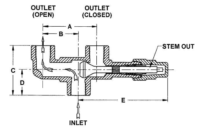
The Valve consists of a Valve inlet or nozzle mounted on the pressurized system, a disc held against the nozzle to prevent flow under normal system operating conditions, a spring to hold the disc closed, and a body/Bonnet to contain the operating elements. The spring load is adjustable to vary the pressure at which the Valve will open.
When a pressure Relief Valve begins to lift, the spring force increases. Thus system pressure must increase if lift is to continue. For this reason pressure Relief Valves are allowed an overpressure allowance to reach full lift. This allowable overpressure is generally 10% for Valves on unfired systems. This margin is relatively small and some means must be provided to assist in the lift effort.
Most pressure Relief Valves, therefore, have a secondary control chamber or huddling chamber to enhance lift. As the disc begins to lift, fluid enters the control chamber exposing a larger area of the disc to system pressure.
This causes an incremental change in force which overcompensates for the increase in spring force and causes the Valve to open at a rapid rate. At the same time, the direction of the fluid flow is reversed and the momentum effect resulting from the change in flow direction further enhances lift. These effects combine to allow the Valve to achieve maximum lift and maximum flow within the allowable overpressure limits. Because of the larger disc area exposed to system pressure after the Valve achieves lift, the Valve will not close until system pressure has been reduced to some level below the set pressure. The design of the control chamber determines where the closing point will occur.
When superimposed back pressure is variable, a balanced bellows or balanced piston design is recommended. A typical balanced bellow is shown on the right. The bellows or piston is designed with an effective pressure area equal to the seat area of the disc. The Bonnet is vented to ensure that the pressure area of the bellows or piston will always be exposed to atmospheric pressure and to provide a telltale sign should the bellows or piston begin to leak. Variations in back pressure, therefore, will have no effect on set pressure. Back pressure may, however, affect flow.
A safety Valve is a pressure Relief Valve actuated by inlet static pressure and characterized by rapid opening or pop action. (It is normally used for steam and air services.)
A low-lift safety Valve is a safety Valve in which the disc lifts automatically such that the actual discharge area is determined by the position of the disc.
A full-lift safety Valve is a safety Valve in which the disc lifts automatically such that the actual discharge area is not determined by the position of the disc.
A Relief Valve is a pressure relief device actuated by inlet static pressure having a gradual lift generally proportional to the increase in pressure over opening pressure. It may be provided with an enclosed spring housing suitable for closed discharge system application and is primarily used for liquid service.
A safety Relief Valve is a pressure Relief Valve characterized by rapid opening or pop action, or by opening in proportion to the increase in pressure over the opening pressure, depending on the application and may be used either for liquid or compressible fluid.
A conventional safety Relief Valve is a pressure Relief Valve which has its spring housing vented to the discharge side of the Valve. The operational characteristics (opening pressure, closing pressure, and relieving capacity) are directly affected by changes of the back pressure on the Valve.
A balanced safety Relief Valve is a pressure Relief Valve which incorporates means of minimizing the effect of back pressure on the operational characteristics (opening pressure, closing pressure, and relieving capacity).
A pilotoperated pressure Relief Valve is a pressure Relief Valve in which the major relieving device is combined with and is controlled by a self-actuated auxiliary pressure Relief Valve.
A poweractuated pressure Relief Valve is a pressure Relief Valve in which the major relieving device is combined with and controlled by a device requiring an external source of energy.
A temperature-actuated pressure Relief Valve is a pressure Relief Valve which may be actuated by external or internal temperature or by pressure on the inlet side.
A vacuum Relief Valve is a pressure relief device designed to admit fluid to prevent an excessive internal vacuum; it is designed to reclose and prevent further flow of fluid after normal conditions have been restored.
Many Codes and Standards are published throughout the world which address the design and application of pressure Relief Valves. The most widely used and recognized of these is the ASME Boiler and Pressure Vessel Code, commonly called the ASME Code.
Most Codes and Standards are voluntary, which means that they are available for use by manufacturers and users and may be written into purchasing and construction specifications. The ASME Code is unique in the United States and Canada, having been adopted by the majority of state and provincial legislatures and mandated by law.
The ASME Code provides rules for the design and construction of pressure vessels. Various sections of the Code cover fired vessels, nuclear vessels, unfired vessels and additional subjects, such as welding and nondestructive examination. Vessels manufactured in accordance with the ASME Code are required to have overpressure protection. The type and design of allowable overpressure protection devices is spelled out in detail in the Code.
is the gauge pressure at which the lift is sufficient to discharge the predetermined flowing capacity. It is equal to the set pressure plus opening pressure difference.
is the cross sectional area upstream or downstream of the body seat calculated from the minimum diameter which is used to calculate the flow capacity without any deduction for obstructions.
is the calculated mass flow from an orifice having a cross sectional area equal to the flow area of the safety Valve without regard to flow losses of the Valve.
the pressure at which a Valve is set on a test rig using a test fluid at ambient temperature. This test pressure includes corrections for service conditions e.g. backpressure or high temperatures.
is that portion of the measured relieving capacity permitted by the applicable code or regulation to be used as a basis for the application of a pressure relieving device.
is the value of increasing static inlet pressure of a pressure Relief Valve at which there is a measurable lift, or at which the discharge becomes continuous as determined by seeing, feeling or hearing.
is the maximum allowable working pressure plus the accumulation as established by reference to the applicable codes for operating or fire contingencies.
Because cleanliness is essential to the satisfactory operation and tightness of a safety Valve, precautions should be taken during storage to keep out all foreign materials. Inlet and outlet protectors should remain in place until the Valve is ready to be installed in the system. Take care to keep the Valve inlet absolutely clean. It is recommended that the Valve be stored indoors in the original shipping container away from dirt and other forms of contamination.
Safety Valves must be handled carefully and never subjected to shocks. Rough handling may alter the pressure setting, deform Valve parts and adversely affect seat tightness and Valve performance.
When it is necessary to use a hoist, the chain or sling should be placed around the Valve body and Bonnet in a manner that will insure that the Valve is in a vertical position to facilitate installation.
Many Valves are damaged when first placed in service because of failure to clean the connection properly when installed. Before installation, flange faces or threaded connections on both the Valve inlet and the vessel and/or line on which the Valve is mounted must be thoroughly cleaned of all dirt and foreign material.
Because foreign materials that pass into and through safety Valves can damage the Valve, the systems on which the Valves are tested and finally installed must also be inspected and cleaned. New systems in particular are prone to contain foreign objects that inadvertently get trapped during construction and will destroy the seating surface when the Valve opens. The system should be thoroughly cleaned before the safety Valve is installed.
The gaskets used must be dimensionally correct for the specific flanges. The inside diameters must fully clear the safety Valve inlet and outlet openings so that the gasket does not restrict flow.
For flanged Valves, draw down all connection studs or bolts evenly to avoid possible distortion of the Valve body. For threaded Valves, do not apply a wrench to the Valve body. Use the hex flats provided on the inlet bushing.
Safety Valves are intended to open and close within a narrow pressure range. Valve installations require accurate design both as to inlet and discharge piping. Refer to International, National and Industry Standards for guidelines.
The Valve should be mounted vertically in an upright position either directly on a nozzle from the pressure vessel or on a short connection fitting that provides a direct, unobstructed flow between the vessel and the Valve. Installing a safety Valve in other than this recommended position will adversely affect its operation.
Discharge piping should be simple and direct. A "broken" connection near the Valve outlet is preferred wherever possible. All discharge piping should be run as direct as is practicable to the point of final release for disposal. The Valve must discharge to a safe disposal area. Discharge piping must be drained properly to prevent the accumulation of liquids on the downstream side of the safety Valve.
The weight of the discharge piping should be carried by a separate support and be properly braced to withstand reactive thrust forces when the Valve relieves. The Valve should also be supported to withstand any swaying or system vibrations.
If the Valve is discharging into a pressurized system be sure the Valve is a "balanced" design. Pressure on the discharge of an "unbalanced" design will adversely affect the Valve performance and set pressure.
The Bonnets of balanced bellows safety Valves must always be vented to ensure proper functioning of the Valve and to provide a telltale in the event of a bellows failure. Do not plug these open vents. When the fluid is flammable, toxic or corrosive, the Bonnet vent should be piped to a safe location.
It is important to remember that a pressure Relief Valve is a safety device employed to protect pressure vessels or systems from catastrophic failure. With this in mind, the application of pressure Relief Valves should be assigned only to fully trained personnel and be in strict compliance with rules provided by the governing codes and standards.

Taylor Valve Technology® is a manufacturer leader in high-quality industrial valves. We deliver safety relief, high-pressure relief, and back pressure relief valves. Our wide array of choke and control valves and pilot-operated valve products are second to none. Products are designed for demanding industrial needs, meeting quality API and ASME Code requirements. High-demand oil & gas industry, chemical plants, power generators, and the processing industry depend on our valves for consistency and durability. Get effective flow control of liquid, steam, and gas. Valves ship from the Taylor Valve Technology, Inc. United States facility. Delivering worldwide, you can depend on quick turnaround times.


 8613371530291