
how to adjust safety valve supplier

The principal type of device used to prevent overpressure in plants is the safety or safety relief valve. The safety valve operates by releasing a volume of fluid from within the plant when a predetermined maximum pressure is reached, thereby reducing the excess pressure in a safe manner.
1. Before the safety valve leaves the factory, we should adjust its opening pressure to reach the set value user specifies. If a user specifies the working pressure level of the spring, then we should adjust it according to the lower limit of the pressure level.
2. Before the safety valve is installed on the protected equipment, users must re-adjust it at the installation site to ensure the set pressure value of the safety valve meets the requirements.
3. In the range of the working pressure level of the spring specified by the nameplate, by turning the adjustment stem to change the compression amount of the spring, we can adjust the opening pressure.
5. To ensure the accuracy of opening pressure value, make sure the medium conditions, such as medium types and temperatures, are as close as possible to the actual operating conditions. When the medium type changes, especially when the dielectric aggregation is different (for example, from the liquid phase to the gas phase), the opening pressure often changes. When the operating temperature rises, the opening pressure is generally reduced. When it’s adjusted at room temperature and used for high temperature, the set pressure value at room temperature should be slightly higher than the required opening pressure value. How high the temperature should be has something to do with the valve structure and material selection, so it should be based on the manufacturer’s instructions.
6. The conventional safety valve is used to fix the additional backpressure. When adjusting opening pressure after the testing (at this time, the backpressure is atmospheric pressure), the set value should be required opening pressure minus additional backpressure.
By adding the 0.1 bar shut-off margin, the safety valve set pressure has to be 10% greater than 6.4 bar. For this example, this means that the safety valve’s set pressure has to be: The set pressure would therefore be chosen as 7.11 bar, provided that this does not exceed the MAWP of the protected system.
Thank you for reading our article and we hope it can help you better understand the adjustment of the opening pressure of the safety valve. If you want to learn more about safety valves, we would like to advise you to visit Adamant Valve homepage for more information.

In order to ensure that the maximum allowable accumulation pressure of any system or apparatus protected by a safety valve is never exceeded, careful consideration of the safety valve’s position in the system has to be made. As there is such a wide range of applications, there is no absolute rule as to where the valve should be positioned and therefore, every application needs to be treated separately.
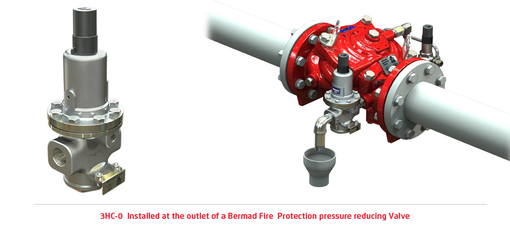
A common steam application for a safety valve is to protect process equipment supplied from a pressure reducing station. Two possible arrangements are shown in Figure 9.3.3.
The safety valve can be fitted within the pressure reducing station itself, that is, before the downstream stop valve, as in Figure 9.3.3 (a), or further downstream, nearer the apparatus as in Figure 9.3.3 (b). Fitting the safety valve before the downstream stop valve has the following advantages:
• The safety valve can be tested in-line by shutting down the downstream stop valve without the chance of downstream apparatus being over pressurised, should the safety valve fail under test.
• When setting the PRV under no-load conditions, the operation of the safety valve can be observed, as this condition is most likely to cause ‘simmer’. If this should occur, the PRV pressure can be adjusted to below the safety valve reseat pressure.
Indeed, a separate safety valve may have to be fitted on the inlet to each downstream piece of apparatus, when the PRV supplies several such pieces of apparatus.
• If supplying one piece of apparatus, which has a MAWP pressure less than the PRV supply pressure, the apparatus must be fitted with a safety valve, preferably close-coupled to its steam inlet connection.
• If a PRV is supplying more than one apparatus and the MAWP of any item is less than the PRV supply pressure, either the PRV station must be fitted with a safety valve set at the lowest possible MAWP of the connected apparatus, or each item of affected apparatus must be fitted with a safety valve.
• The safety valve must be located so that the pressure cannot accumulate in the apparatus viaanother route, for example, from a separate steam line or a bypass line.
It could be argued that every installation deserves special consideration when it comes to safety, but the following applications and situations are a little unusual and worth considering:
• Fire - Any pressure vessel should be protected from overpressure in the event of fire. Although a safety valve mounted for operational protection may also offer protection under fire conditions,such cases require special consideration, which is beyond the scope of this text.
• Exothermic applications - These must be fitted with a safety valve close-coupled to the apparatus steam inlet or the body direct. No alternative applies.
• Safety valves used as warning devices - Sometimes, safety valves are fitted to systems as warning devices. They are not required to relieve fault loads but to warn of pressures increasing above normal working pressures for operational reasons only. In these instances, safety valves are set at the warning pressure and only need to be of minimum size. If there is any danger of systems fitted with such a safety valve exceeding their maximum allowable working pressure, they must be protected by additional safety valves in the usual way.
In order to illustrate the importance of the positioning of a safety valve, consider an automatic pump trap (see Block 14) used to remove condensate from a heating vessel. The automatic pump trap (APT), incorporates a mechanical type pump, which uses the motive force of steam to pump the condensate through the return system. The position of the safety valve will depend on the MAWP of the APT and its required motive inlet pressure.
This arrangement is suitable if the pump-trap motive pressure is less than 1.6 bar g (safety valve set pressure of 2 bar g less 0.3 bar blowdown and a 0.1 bar shut-off margin). Since the MAWP of both the APT and the vessel are greater than the safety valve set pressure, a single safety valve would provide suitable protection for the system.
However, if the pump-trap motive pressure had to be greater than 1.6 bar g, the APT supply would have to be taken from the high pressure side of the PRV, and reduced to a more appropriate pressure, but still less than the 4.5 bar g MAWP of the APT. The arrangement shown in Figure 9.3.5 would be suitable in this situation.
Here, two separate PRV stations are used each with its own safety valve. If the APT internals failed and steam at 4 bar g passed through the APT and into the vessel, safety valve ‘A’ would relieve this pressure and protect the vessel. Safety valve ‘B’ would not lift as the pressure in the APT is still acceptable and below its set pressure.
It should be noted that safety valve ‘A’ is positioned on the downstream side of the temperature control valve; this is done for both safety and operational reasons:
Operation - There is less chance of safety valve ‘A’ simmering during operation in this position,as the pressure is typically lower after the control valve than before it.
Also, note that if the MAWP of the pump-trap were greater than the pressure upstream of PRV ‘A’, it would be permissible to omit safety valve ‘B’ from the system, but safety valve ‘A’ must be sized to take into account the total fault flow through PRV ‘B’ as well as through PRV ‘A’.
A pharmaceutical factory has twelve jacketed pans on the same production floor, all rated with the same MAWP. Where would the safety valve be positioned?
One solution would be to install a safety valve on the inlet to each pan (Figure 9.3.6). In this instance, each safety valve would have to be sized to pass the entire load, in case the PRV failed open whilst the other eleven pans were shut down.
If additional apparatus with a lower MAWP than the pans (for example, a shell and tube heat exchanger) were to be included in the system, it would be necessary to fit an additional safety valve. This safety valve would be set to an appropriate lower set pressure and sized to pass the fault flow through the temperature control valve (see Figure 9.3.8).
A safety valve’s set pressure is the pressure at which it audibly opens for the first time. If you want to change the set pressure of your valve, it may be necessary to replace the installed spring.
Under normal conditions, the set pressure is equal to the test pressure. At temperatures above 100 °C or when compensating for back pressure on the outlet face, the test pressure may deviate from the set pressure.
Please note that unauthorised persons are prohibited from changing the set pressure of a safety valve. In addition, after a pressure change, the safety valve must be sealed and re-stamped in accordance with the regulations.

A safety valve is an important part of any engineering system or industrial installation working with media under high pressure, it is the safety of the operating personnel, the exclusion of equipment destruction and emergency situations.
Conveniently, the safety valve supplier can service, adjust or reset the pressure, and can repair and replace parts if necessary. LESER safety valves are known all over the world and are widely used in industry and heating. To provide customers with more options for service safety valves, OPEKS Energosystems, the official distributor of LESER, uses a proprietary set of LESER equipment and tools to set up and maintain valves at its own production facilities.
Setting the required response pressure of the safety valve consists of the following main steps:Fastening the safety valve using a standard mount in a tuning stand. Preparing to set up.
Valve assembly. Checking the tightness of the valve in the closed position, at a pressure less than the design one to prevent leakage of the working medium. Valve seat polishing, other work if necessary.
Setting up safety valves at the OPEKS production facility allows us to provide a shorter delivery time, shorten the period of service work, provide more opportunities and better service to our customers. Also, the company"s warehouse regularly maintains new valves for water, gases of different diameters with a response pressure, which is most often found in inquiries.
Cooperation with OPEKS Energosystems, which supplies and maintains LESER safety valves, as well as manufactures heat exchange equipment, modular units, steam condensate systems and other heat and power equipment, favorably stands out for its great opportunities for our Clients.

A little product education can make you look super smart to customers, which usually means more orders for everything you sell. Here’s a few things to keep in mind about safety valves, so your customers will think you’re a genius.
A safety valve is required on anything that has pressure on it. It can be a boiler (high- or low-pressure), a compressor, heat exchanger, economizer, any pressure vessel, deaerator tank, sterilizer, after a reducing valve, etc.
There are four main types of safety valves: conventional, bellows, pilot-operated, and temperature and pressure. For this column, we will deal with conventional valves.
A safety valve is a simple but delicate device. It’s just two pieces of metal squeezed together by a spring. It is passive because it just sits there waiting for system pressure to rise. If everything else in the system works correctly, then the safety valve will never go off.
A safety valve is NOT 100% tight up to the set pressure. This is VERY important. A safety valve functions a little like a tea kettle. As the temperature rises in the kettle, it starts to hiss and spit when the water is almost at a boil. A safety valve functions the same way but with pressure not temperature. The set pressure must be at least 10% above the operating pressure or 5 psig, whichever is greater. So, if a system is operating at 25 psig, then the minimum set pressure of the safety valve would be 30 psig.
Most valve manufacturers prefer a 10 psig differential just so the customer has fewer problems. If a valve is positioned after a reducing valve, find out the max pressure that the equipment downstream can handle. If it can handle 40 psig, then set the valve at 40. If the customer is operating at 100 psig, then 110 would be the minimum. If the max pressure in this case is 150, then set it at 150. The equipment is still protected and they won’t have as many problems with the safety valve.
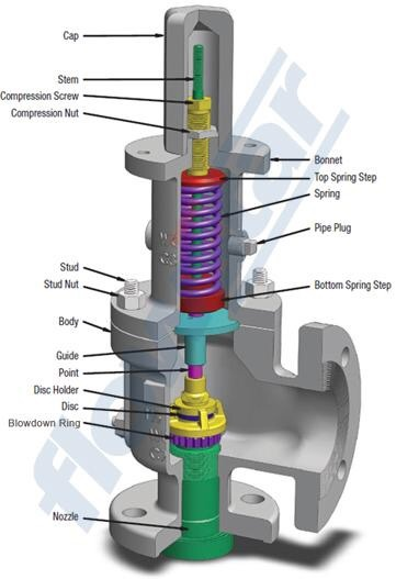
Here’s another reason the safety valve is set higher than the operating pressure: When it relieves, it needs room to shut off. This is called BLOWDOWN. In a steam and air valve there is at least one if not two adjusting rings to help control blowdown. They are adjusted to shut the valve off when the pressure subsides to 6% below the set pressure. There are variations to 6% but for our purposes it is good enough. So, if you operate a boiler at 100 psig and you set the safety valve at 105, it will probably leak. But if it didn’t, the blowdown would be set at 99, and the valve would never shut off because the operating pressure would be greater than the blowdown.
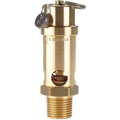
All safety valves that are on steam or air are required by code to have a test lever. It can be a plain open lever or a completely enclosed packed lever.
Safety valves are sized by flow rate not by pipe size. If a customer wants a 12″ safety valve, ask them the flow rate and the pressure setting. It will probably turn out that they need an 8×10 instead of a 12×16. Safety valves are not like gate valves. If you have a 12″ line, you put in a 12″ gate valve. If safety valves are sized too large, they will not function correctly. They will chatter and beat themselves to death.
Safety valves need to be selected for the worst possible scenario. If you are sizing a pressure reducing station that has 150 psig steam being reduced to 10 psig, you need a safety valve that is rated for 150 psig even though it is set at 15. You can’t put a 15 psig low-pressure boiler valve after the reducing valve because the body of the valve must to be able to handle the 150 psig of steam in case the reducing valve fails.
The seating surface in a safety valve is surprisingly small. In a 3×4 valve, the seating surface is 1/8″ wide and 5″ around. All it takes is one pop with a piece of debris going through and it can leak. Here’s an example: Folgers had a plant in downtown Kansas City that had a 6×8 DISCONTINUED Consolidated 1411Q set at 15 psig. The valve was probably 70 years old. We repaired it, but it leaked when plant maintenance put it back on. It was after a reducing valve, and I asked him if he played with the reducing valve and brought the pressure up to pop the safety valve. He said no, but I didn’t believe him. I told him the valve didn’t leak when it left our shop and to send it back.
If there is a problem with a safety valve, 99% of the time it is not the safety valve or the company that set it. There may be other reasons that the pressure is rising in the system before the safety valve. Some ethanol plants have a problem on starting up their boilers. The valves are set at 150 and they operate at 120 but at startup the pressure gets away from them and there is a spike, which creates enough pressure to cause a leak until things get under control.
If your customer is complaining that the valve is leaking, ask questions before a replacement is sent out. What is the operating pressure below the safety valve? If it is too close to the set pressure then they have to lower their operating pressure or raise the set pressure on the safety valve.
Is the valve installed in a vertical position? If it is on a 45-degree angle, horizontal, or upside down then it needs to be corrected. I have heard of two valves that were upside down in my 47 years. One was on a steam tractor and the other one was on a high-pressure compressor station in the New Mexico desert. He bought a 1/4″ valve set at 5,000 psig. On the outlet side, he left the end cap in the outlet and put a pin hole in it so he could hear if it was leaking or not. He hit the switch and when it got up to 3,500 psig the end cap came flying out like a missile past his nose. I told him to turn that sucker in the right direction and he shouldn’t have any problems. I never heard from him so I guess it worked.
If the set pressure is correct, and the valve is vertical, ask if the outlet piping is supported by something other than the safety valve. If they don’t have pipe hangers or a wall or something to keep the stress off the safety valve, it will leak.
There was a plant in Springfield, Mo. that couldn’t start up because a 2″ valve was leaking on a tank. It was set at 750 psig, and the factory replaced it 5 times. We are not going to replace any valves until certain questions are answered. I was called to solve the problem. The operating pressure was 450 so that wasn’t the problem. It was in a vertical position so we moved on to the piping. You could tell the guy was on his cell phone when I asked if there was any piping on the outlet. He said while looking at the installation that he had a 2″ line coming out into a 2×3 connection going up a story into a 3×4 connection and going up another story. I asked him if there was any support for this mess, and he hung up the phone. He didn’t say thank you, goodbye, or send me a Christmas present.
Pipe dope is another problem child. Make sure your contractors ease off on the pipe dope. That is enough for today, class. Thank you for your patience. And thank you for your business.
This website is using a security service to protect itself from online attacks. The action you just performed triggered the security solution. There are several actions that could trigger this block including submitting a certain word or phrase, a SQL command or malformed data.

The National Board strives to keep information in the hands of website users. Provided here are more than 70 Technical Articles previously published in the National Board BULLETINand/or from the proceedings of past General Meetings.
Valve Check Inc. is a manufacture of high-quality check valves offered in a variety of sizes ranging from 1/8, 1/4, 1/2, 3/4, 1 inch though 2 inch and up to 4" NPT. Configurations are offered in Male x Male, Male x Female, Female x Male, and Female x Female.
Valve Check specializes in manufacturing the lowest pressure drop check valves and offers the highest flow check valves of any manufacturer. Pressures range from low pressure .5 psi to 500 psi high pressure check valves.
Industry leading pressure and safety relief valve designs with over 140 years of technical and application expertise providing custom engineered solutions for O&G, Refining, Chemical, Petrochemical, Process and Power applications. Our designs meet global and local codes and standards (API 526; ASME Section I, IV & VIII; EN ISO 4126; PED & more). Gain insight into the performance of your pressure relief valves with wireless monitoring.

1 Piece Ball Valve1 Piece Cast Iron Screwed Ball Valve1 Piece Flanged Ball Valve1 Piece Screwed Ball Valve2 Piece Ball valve2 Piece Cast Steel Ball Valve2 Piece Flanged Ball Valve2 Piece Forged Steel Ball Valve2 Piece Screwed Ball Valve3 Piece Ball Valve3 Piece Cast Iron Ball Valve3 Piece Cast Steel Ball Valve3 Piece Flanged Ball Valve3 Piece Forged Steel Ball Valve3 Piece Reduced Port Ball Valve3 Piece Screwed Ball Valve3 Way Converging and Diverging Control Valve3 Way Plug Valve3 Way Pneumatic Diaphragm Control ValveAir ValveAlloy 20 2 Piece Ball ValveAlloy 20 2 Piece Screwed Ball ValveAlloy 20 3 Piece Ball ValveAlloy 20 3 Piece Screwed Ball ValveAlloy 20 Ball ValveAlloy 20 Dual Plate Lug Type Check ValveAlloy 20 Floating Ball ValveAlloy 20 Swing Check ValveAlloy 20 Trunnion Mounted Ball ValveAlloy 20 ValvesAlloy 20 Wafer Butterfly ValveAlloy Butterfly ValveAlloy Check valveAlloy Dual Plate Wafer Check ValveAlloy Flanged Gate ValveAlloy Flanged Globe ValveAlloy Gate ValveAlloy Gate ValvesAlloy Globe ValvesAlloy Lug Butterfly ValveAlloy Plug ValveAlloy Pressure Seal Globe ValveAluminium Bronze 3 Piece Ball ValveAluminium Bronze Ball ValveAluminium Bronze Butterfly ValveAluminium Bronze Check ValveAluminium Bronze Floating Ball ValveAluminium Bronze Gate ValveAluminium Bronze Lug Butterfly ValveAluminium Bronze Swing Check ValveAluminium Bronze Triple offset Lug Butterfly ValveAluminium Bronze Trunnion Ball ValveAluminium Bronze valvesAluminium Bronze Wafer Butterfly ValveAluminium Dual Plate Wafer Check ValveAluminum Bronze Globe ValveAngle Globe ValveANSI Gate ValveANSI Globe ValveAPI Aluminium Bronze Triple offset Lug Butterfly ValveAPI Gate ValveAPI Globe ValveAustenitic Steel Big Size Ball ValveAustenitic Steel ValvesAWWA Butterfly ValveAWWA Gate ValveAWWA Non Rising Stem Gate ValveAWWA OS&Y Gate ValveAWWA StrainerAWWA Wafer Butterfly ValveAWWA Y StrainerBalancing ValveBall Float Steam TrapBall ValveBellow Seal Globe ValveBi Directional Knife Gate ValveBimetallic Steam TrapBlock and Bleed valveBrass Ball ValveBrass Ball ValvesBrass Check ValvesBrass Flanged Ball ValveBrass Flanged Gate ValveBrass Flanged Globe ValveBrass Gate ValveBrass Gate ValvesBrass Globe ValveBrass Globe ValvesBrass Safety ValveBrass Swing Check ValveBrass ValveBrass Vertical Check ValveBrass Y StrainerBronze Butterfly ValveBronze Check ValveBronze Flanged Gate ValveBronze Flanged Globe ValveBronze Floating Ball ValveBronze Gate ValveBronze Gate ValvesBronze Globe ValveBronze Globe ValvesBronze Swing Check ValveBronze ValveBronze Wafer Butterfly ValveBronze Wafer Check ValveBS Cast Iron Gate valveBS Cast Steel Gate ValveBS Ductile Iron Gate ValveBS Globe ValveBS Non Rising Stem Gate ValveBS NRS Carbon Steel Gate ValveBS NRS Cast Iron Gate ValveBS NRS Ductile Iron Gate ValveBS Rising Stem Gate ValveBS Soft Seat Gate ValveBS Stainless Steel Gate ValveButterfly ValveCarbon Steel Bellow Seal Globe ValveCast Floating Ball ValveCast Iron And Cast Steel Ball ValveCast Iron Diaphragm ValveCasting Trunnion Ball Valvecheck valveConnection Lift Plug ValveControl ValveCryogenic Ball ValveCryogenic Check ValveCryogenic Emergency Cut off ValveCryogenic Gate ValveCryogenic Globe ValveCryogenic Long Stem Globe ValveCryogenic Pneumatic Actuated Globe ValveCryogenic Short Stem Globe ValveCryogenic Steam Jacket Globe ValveCryogenic ValveDiaphragm ValveDIN Globe ValveDIN Non Rising Stem Ductile Iron Gate ValveDIN Non Rising Stem Gate ValveDIN NRS Cast Iron Gate ValveDIN Rising Stem Cast Iron Gate ValveDIN Rising Stem Ductile Iron Gate ValveDIN Rising Stem Gate ValveDIN Soft Seat Gate ValveDirect Acting Pressure Reducing ValveDouble Block and Bleed Ball ValveDouble Disc Gate ValveDouble Eccentric Butterfly ValveDouble Offset Butterfly ValveDouble Orifice Air Release ValveDouble Orifice Kinetic Air ValveDual Plate Lug Check ValveDual Plate Wafer Check ValveDuctile Iron Diaphragm ValveDuplex 1B 3 PC Ball ValveDuplex 3 Piece Ball ValveDuplex Basket StrainerDuplex Butterfly ValveDuplex Check ValveDuplex Dual Plate Lug Type Check ValveDuplex Dual Plate Wafer Check ValveDuplex Floating Ball ValveDuplex Gate ValveDuplex Globe ValveDuplex High Pressure Ball ValveDuplex Lug Type Butterfly ValveDuplex Steel Ball ValveDuplex steel ValveDuplex Swing Check ValveDuplex Top Entry Ball ValveDuplex Trunnion Mounted Ball ValveDuplex Wafer Butterfly ValveEccentric Plug ValveElectric 3 Way Control ValveElectric Actuated 2 Piece Ball ValveElectric Actuated 2 Piece Flanged Ball ValveElectric Actuated 2 Piece Screwed Ball ValveElectric Actuated Ball ValveElectric Actuated Butterfly ValveElectric Actuated Flanged Ball ValveElectric Actuated Floating Forged Ball ValveElectric Actuated Gate ValveElectric Actuated Globe Control ValveElectric Actuated Globe ValveElectric Actuated High Pressure Ball ValvesElectric Actuated High Pressure Direct Mounting Ball ValvesElectric Actuated Lug Butterfly ValveElectric Actuated Metal-Seated Trunnion-Mounted Forged Ball ValveElectric Actuated Three Piece Ball ValveElectric Actuated Three Way Ball ValveElectric Actuated Trunnion-Mounted Casting Ball ValveElectric Actuated ValvesElectric Actuated Wafer Butterfly ValveElectric Cage Type Control ValveElectric Control ValveElectric Double Seat Control ValveElectric O-type Shut-off Control ValveElectric Single Seat Control ValveF22/Alloy Steel Pressure Seal Globe ValveF317L Gate ValveF317L Globe ValveF317L ValvesF321 Gate ValveF321 Globe ValveF321 ValvesF347 3 Piece Ball ValveF347 Ball ValveF347 Butterfly ValveF347 Check ValveF347 Dual Plate Lug Type Check ValveF347 Dual Plate Wafer Check ValveF347 Floating Ball ValveF347 Gate ValveF347 Globe ValveF347 Lug Type Butterfly ValveF347 Swing Check ValveF347 Trunnion Mounted Ball ValveF347 ValvesF347 Wafer Butterfly ValveF44 Gate ValveF44 Globe valvesF44 ValvesF51 Super Duplex Ball ValveF53/F55 Super Duplex Globe ValveFeed Water Control ValveFlanged Butterfly ValveFlanged Knife gate ValveFloat Control ValveFloating Ball ValveFluorine Lined Single Seat Control ValveFoot ValveForged Cryogenic Trunnion Ball ValveForged Floating Ball ValveForged Steel Ball ValveForged Steel Gate ValveForged Steel Globe ValveForged Steel Swing Check ValveForged Trunnion Ball ValveFull Lift Pressure Safety ValveFull Lift Safety ValveFully Welded Ball ValveGate ValveGlobe ValveHastelloy Ball ValveHastelloy C276 2 Piece Flanged Ball ValveHastelloy C276 2 Piece Screwed Ball ValveHastelloy C276 3 Piece Screwed Ball ValveHastelloy C276/B3 3 Piece Ball ValveHastelloy C276/B3 Butterfly ValveHastelloy C276/B3 Dual Plate Lug Type Check ValveHastelloy C276/B3 Dual Plate Wafer Check ValveHastelloy C276/B3 Floating Ball ValveHastelloy C276/B3 Gate ValvesHastelloy C276/B3 Globe ValveHastelloy C276/B3 Lug Butterfly ValveHastelloy C276/B3 Swing Check valveHastelloy C276/B3 Trunnion Mounted Ball ValveHastelloy C276/B3 ValvesHastelloy C276/B3 Wafer Butterfly ValveHastelloy Check ValveHeavy Duty Investment Casting Ball ValveHigh Performance Lug Butterfly ValveHigh Performance Wafer Butterfly ValveIncoloy 2 Piece Ball ValveIncoloy 3 Piece Ball ValveIncoloy Gate ValveIncoloy Globe ValveIncoloy ValvesInconel 2 Piece Ball ValveInconel 3 Piece Ball ValveInconel Ball ValveInconel Butterfly ValveInconel Check ValveInconel Dual Plate Lug Type Check ValveInconel Dual Plate Wafer Check ValveInconel Floating Ball ValveInconel Gate ValveInconel Globe ValveInconel Lug Butterfly ValveInconel safety relief valveInconel Swing Check ValveInconel Trunnion Mounted Ball ValveInconel ValveInconel Wafer Butterfly ValveInverted Bucket Steam TrapInvestment Casting Ball ValveJacketed Ball ValveJacketed Plug ValveKnife Gate ValveLift Check valveLow Lift Pressure Safety ValveLow Lift Safety ValveLubricated Plug valveLug Butterfly ValveMonel 2 Piece Ball ValveMonel 3 Piece Ball ValveMonel 400 2 Piece Flanged Ball ValveMonel 400 ValvesMonel Ball ValveMonel Butterfly ValveMonel Check ValveMonel Dual Plate Lug Check ValveMonel Dual Plate Wafer Check ValveMonel Floating Ball ValveMonel Forged Trunnion Mounted Ball ValveMonel Gate ValveMonel Globe ValveMonel High Pressure Ball ValveMonel Lug Type Butterfly ValveMonel Swing Check ValveMonel Top Entry Ball ValveMonel Trunnion Mounted Ball ValveMonel ValvesMonel Wafer Butterfly ValveNeedle valveNon Slam Swing Check ValveNon-Lubricated Sleeved Plug ValveNon-Rising Stem Gate ValveNon-Slam Swing Check ValveOrbit Plug ValvePilot Operated Pressure Reducing ValvePilot Operated ValvePressure Relief ValvePiston ValvePlug ValvePlunger ValvePneumatic Actuated 2 Piece Ball ValvePneumatic Actuated 2 Piece Flanged Ball ValvePneumatic Actuated Ball ValvePneumatic Actuated Butterfly ValvePneumatic Actuated Flanged Ball ValvePneumatic Actuated Flanged Butterfly ValvePneumatic Actuated Gate ValvePneumatic Actuated Globe type Control ValvePneumatic Actuated Lug Butterfly ValvePneumatic Actuated Three Piece Ball valvePneumatic Actuated Three Way Ball valvePneumatic Actuated Three Way Heavy Duty Ball ValvePneumatic Actuated Two Piece Ball ValvePneumatic Actuated ValvesPneumatic Actuated Wafer Butterfly ValvePneumatic Angle Control ValvePneumatic Angle Seat Control ValvePneumatic Angle Type High Pressure Regulating Control ValvePneumatic Bi Directional Knife Gate valvePneumatic Cage Control ValvePneumatic Control ValvePneumatic Double Seat Control ValvePneumatic Flow Control ValvePneumatic Knife Gate ValvePneumatic Metal Seat Flanged Ball ValvePneumatic Single Seat Globe Control ValvePneumatic Sleeve Type Control ValvePneumatic Three piece Ball ValvePneumatic Three Piece Flanged Ball ValvePneumatic Three Way Ball ValvePneumatic Three Way Flanged Ball ValvePneumatic Trunnion Casting Ball ValvePneumatic Trunnion Forged Ball ValvePneumatic Trunnion Forged Metal Seat Ball ValvePneumatic Unidirectional Knife Gate ValvePressure Reducing ValvePressure Safety ValvePressure Seal Gate ValvePressure Seal Globe ValvePressure Seal Swing Check ValveRotary Airlock ValveSafety ValveSimplex Basket StrainersSingle Orifice Air ValveSingle Plate Wafer Check ValveSlab Gate ValveSlurry Knife Gate ValveSoft Seal Gate ValveSpeciality ValveSS304 Bellow Seal Globe ValveSS316 Bellow Seal Globe ValveSS316L Gate ValveSS316L Lug Butterfly ValveSS316L Wafer Butterfly ValveSteam Pressure Reducing ValveSteam Safety ValveSteam TrapStrainersSuction DiffuserSuper Duplex 2 Piece Ball ValveSuper Duplex 3 Piece Ball ValveSuper Duplex 5A Flanged Gate ValveSuper Duplex 5A Globe ValveSuper Duplex 5A Swing Check ValveSuper Duplex Ball ValveSuper Duplex Butterfly ValveSuper Duplex Check ValveSuper Duplex Dual Plate Lug Type Check ValveSuper Duplex Dual Plate Wafer Check ValveSuper Duplex Floating Ball ValveSuper Duplex Gate ValveSuper Duplex Gate ValvesSuper Duplex Globe ValveSuper Duplex High Pressure Ball ValveSuper Duplex Knife Gate ValveSuper Duplex Lug Butterfly ValveSuper Duplex Pressure Reducing ValveSuper Duplex Top Entry Ball ValveSuper Duplex Trunnion Mounted Ball ValveSuper Duplex ValvesSuper Duplex Wafer Butterfly ValveSurge Anticipator ValveSwing Check ValveThermal Safety ValveThermodynamic Steam TrapThermostatic Steam TrapThree Piece Flanged Ball ValveThree Way Ball ValveThrough Conduit Knife Gate ValveTilting Disc Check ValveTitanium 3 Piece Ball ValveTitanium Ball ValveTitanium Butterfly ValveTitanium Check ValveTitanium Dual Plate Lug Type Check ValveTitanium Dual Plate Wafer Check ValveTitanium Floating Ball ValveTitanium Forged Trunnion Mounted Ball ValveTitanium Gate ValveTitanium Globe ValveTitanium Gr.2 2pc Flanged Ball ValveTitanium Gr.2 3pc Ball ValveTitanium Gr.5 2pc Flanged Ball ValveTitanium Gr.5 3pc Ball ValveTitanium Lug Butterfly ValveTitanium Swing Check ValveTitanium Trunnion Mounted Ball ValveTitanium valvesTitanium Wafer Butterfly ValveTop Entry Ball ValveTriple Duty ValveTriple Eccentric Butterfly ValveTriple Offset Butterfly ValveTrunnion Ball ValveTwin Seal Plug ValveUL/FM Approved ValvesUnidirectional Knife Gate ValveWafer Butterfly ValveWater Pressure Reducing ValveY StrainerY Type Globe ValveZirconium Floating Ball ValveZirconium Gate ValveZirconium Globe ValveZirconium Valves

Boiler explosions have been responsible for widespread damage to companies throughout the years, and that’s why today’s boilers are equipped with safety valves and/or relief valves. Boiler safety valves are designed to prevent excess pressure, which is usually responsible for those devastating explosions. That said, to ensure that boiler safety valves are working properly and providing adequate protection, they must meet regulatory specifications and require ongoing maintenance and periodic testing. Without these precautions, malfunctioning safety valves may fail, resulting in potentially disastrous consequences.
Boiler safety valves are activated by upstream pressure. If the pressure exceeds a defined threshold, the valve activates and automatically releases pressure. Typically used for gas or vapor service, boiler safety valves pop fully open once a pressure threshold is reached and remain open until the boiler pressure reaches a pre-defined, safe lower pressure.
Boiler relief valves serve the same purpose – automatically lowering boiler pressure – but they function a bit differently than safety valves. A relief valve doesn’t open fully when pressure exceeds a defined threshold; instead, it opens gradually when the pressure threshold is exceeded and closes gradually until the lower, safe threshold is reached. Boiler relief valves are typically used for liquid service.
There are also devices known as “safety relief valves” which have the characteristics of both types discussed above. Safety relief valves can be used for either liquid or gas or vapor service.
Nameplates must be fastened securely and permanently to the safety valve and remain readable throughout the lifespan of the valve, so durability is key.
The National Board of Boiler and Pressure Vessel Inspectors offers guidance and recommendations on boiler and pressure vessel safety rules and regulations. However, most individual states set forth their own rules and regulations, and while they may be similar across states, it’s important to ensure that your boiler safety valves meet all state and local regulatory requirements.
The National Board published NB-131, Recommended Boiler and Pressure Vessel Safety Legislation, and NB-132, Recommended Administrative Boiler and Pressure Vessel Safety Rules and Regulationsin order to provide guidance and encourage the development of crucial safety laws in jurisdictions that currently have no laws in place for the “proper construction, installation, inspection, operation, maintenance, alterations, and repairs” necessary to protect workers and the public from dangerous boiler and pressure vessel explosions that may occur without these safeguards in place.
The documents are meant to be used as a guide for developing local laws and regulations and also may be used to update a jurisdiction’s existing requirements. As such, they’re intended to be modifiable to meet any jurisdiction’s local conditions.
The American Society of Mechanical Engineers (ASME) governs the code that establishes guidelines and requirements for safety valves. Note that it’s up to plant personnel to familiarize themselves with the requirements and understand which parts of the code apply to specific parts of the plant’s steam systems.
High steam capacity requirements, physical or economic constraints may make the use of a single safety valve impossible. In these cases, using multiple safety valves on the same system is considered an acceptable practice, provided that proper sizing and installation requirements are met – including an appropriately sized vent pipe that accounts for the total steam venting capacity of all valves when open at the same time.
The lowest rating (MAWP or maximum allowable working pressure) should always be used among all safety devices within a system, including boilers, pressure vessels, and equipment piping systems, to determine the safety valve set pressure.
General guidance on proper installation may seem like common sense to experienced installers and inspectors. A few of the most important guidelines and best practices include:
Avoid isolating safety valves from the system, such as by installing intervening shut-off valves located between the steam component or system and the inlet.
Contact the valve supplier immediately for any safety valve with a broken wire seal, as this indicates that the valve is unsafe for use. Safety valves are sealed and certified in order to prevent tampering that can prevent proper function.
Avoid attaching vent discharge piping directly to a safety valve, which may place unnecessary weight and additional stress on the valve, altering the set pressure.
Emergency situations are not the only times relief valves are active; once installed they continuously regulate the flow of substance. They can also be pre-set to open when the pressure or temperature gets to a certain point that may be dangerous. Generally valves are placed on or near the pump head of the hose, pipe or tube. A wide variety of relief valve designs exist, although most resemble ball-check valves, swing check valves or diaphragm valves.
This last is particularly useful when controlling a flow of fluids that contains suspended solids. Most relief valves are spring operated, as are the majority of check valves. One specialized type of relief valve is known as a vacuum relief valve. As opposed to a normal relief valve, which relieves high pressure, a vacuum relief valve is used to relieve dangerously low pressures, or vacuums, by inserting air or an inert gas.
Like every other type of check valve, relief valves may be constructed from a variety of materials, including PVC, brass, ductile iron, copper, polyethylene, polypropylene, aluminum, steel, stainless steel and rubber. Which raw substance is used to produce each relief valve depends on the environment said relief valve will be in. The wrong product could result in erosion or contamination of the process stream. However, as long as research is done, finding the appropriate type of relief valve is possible. Every plumbing or fluid transfer application in the industrial, commercial and domestic arenas employ or will employ check valves. In fact, check valves of all kinds are an essential part of every day life. Because they need not be supervised to function and prevent product malfunction, check valves are not only desirable but often required by law to ensure the safety of water, gas and pressure applications.

This website is using a security service to protect itself from online attacks. The action you just performed triggered the security solution. There are several actions that could trigger this block including submitting a certain word or phrase, a SQL command or malformed data.


 8613371530291