
how safety valve works for sale

A little product education can make you look super smart to customers, which usually means more orders for everything you sell. Here’s a few things to keep in mind about safety valves, so your customers will think you’re a genius.
A safety valve is required on anything that has pressure on it. It can be a boiler (high- or low-pressure), a compressor, heat exchanger, economizer, any pressure vessel, deaerator tank, sterilizer, after a reducing valve, etc.
There are four main types of safety valves: conventional, bellows, pilot-operated, and temperature and pressure. For this column, we will deal with conventional valves.
A safety valve is a simple but delicate device. It’s just two pieces of metal squeezed together by a spring. It is passive because it just sits there waiting for system pressure to rise. If everything else in the system works correctly, then the safety valve will never go off.
A safety valve is NOT 100% tight up to the set pressure. This is VERY important. A safety valve functions a little like a tea kettle. As the temperature rises in the kettle, it starts to hiss and spit when the water is almost at a boil. A safety valve functions the same way but with pressure not temperature. The set pressure must be at least 10% above the operating pressure or 5 psig, whichever is greater. So, if a system is operating at 25 psig, then the minimum set pressure of the safety valve would be 30 psig.
Most valve manufacturers prefer a 10 psig differential just so the customer has fewer problems. If a valve is positioned after a reducing valve, find out the max pressure that the equipment downstream can handle. If it can handle 40 psig, then set the valve at 40. If the customer is operating at 100 psig, then 110 would be the minimum. If the max pressure in this case is 150, then set it at 150. The equipment is still protected and they won’t have as many problems with the safety valve.
Here’s another reason the safety valve is set higher than the operating pressure: When it relieves, it needs room to shut off. This is called BLOWDOWN. In a steam and air valve there is at least one if not two adjusting rings to help control blowdown. They are adjusted to shut the valve off when the pressure subsides to 6% below the set pressure. There are variations to 6% but for our purposes it is good enough. So, if you operate a boiler at 100 psig and you set the safety valve at 105, it will probably leak. But if it didn’t, the blowdown would be set at 99, and the valve would never shut off because the operating pressure would be greater than the blowdown.
All safety valves that are on steam or air are required by code to have a test lever. It can be a plain open lever or a completely enclosed packed lever.
Safety valves are sized by flow rate not by pipe size. If a customer wants a 12″ safety valve, ask them the flow rate and the pressure setting. It will probably turn out that they need an 8×10 instead of a 12×16. Safety valves are not like gate valves. If you have a 12″ line, you put in a 12″ gate valve. If safety valves are sized too large, they will not function correctly. They will chatter and beat themselves to death.
Safety valves need to be selected for the worst possible scenario. If you are sizing a pressure reducing station that has 150 psig steam being reduced to 10 psig, you need a safety valve that is rated for 150 psig even though it is set at 15. You can’t put a 15 psig low-pressure boiler valve after the reducing valve because the body of the valve must to be able to handle the 150 psig of steam in case the reducing valve fails.
The seating surface in a safety valve is surprisingly small. In a 3×4 valve, the seating surface is 1/8″ wide and 5″ around. All it takes is one pop with a piece of debris going through and it can leak. Here’s an example: Folgers had a plant in downtown Kansas City that had a 6×8 DISCONTINUED Consolidated 1411Q set at 15 psig. The valve was probably 70 years old. We repaired it, but it leaked when plant maintenance put it back on. It was after a reducing valve, and I asked him if he played with the reducing valve and brought the pressure up to pop the safety valve. He said no, but I didn’t believe him. I told him the valve didn’t leak when it left our shop and to send it back.
If there is a problem with a safety valve, 99% of the time it is not the safety valve or the company that set it. There may be other reasons that the pressure is rising in the system before the safety valve. Some ethanol plants have a problem on starting up their boilers. The valves are set at 150 and they operate at 120 but at startup the pressure gets away from them and there is a spike, which creates enough pressure to cause a leak until things get under control.
If your customer is complaining that the valve is leaking, ask questions before a replacement is sent out. What is the operating pressure below the safety valve? If it is too close to the set pressure then they have to lower their operating pressure or raise the set pressure on the safety valve.
Is the valve installed in a vertical position? If it is on a 45-degree angle, horizontal, or upside down then it needs to be corrected. I have heard of two valves that were upside down in my 47 years. One was on a steam tractor and the other one was on a high-pressure compressor station in the New Mexico desert. He bought a 1/4″ valve set at 5,000 psig. On the outlet side, he left the end cap in the outlet and put a pin hole in it so he could hear if it was leaking or not. He hit the switch and when it got up to 3,500 psig the end cap came flying out like a missile past his nose. I told him to turn that sucker in the right direction and he shouldn’t have any problems. I never heard from him so I guess it worked.
If the set pressure is correct, and the valve is vertical, ask if the outlet piping is supported by something other than the safety valve. If they don’t have pipe hangers or a wall or something to keep the stress off the safety valve, it will leak.
There was a plant in Springfield, Mo. that couldn’t start up because a 2″ valve was leaking on a tank. It was set at 750 psig, and the factory replaced it 5 times. We are not going to replace any valves until certain questions are answered. I was called to solve the problem. The operating pressure was 450 so that wasn’t the problem. It was in a vertical position so we moved on to the piping. You could tell the guy was on his cell phone when I asked if there was any piping on the outlet. He said while looking at the installation that he had a 2″ line coming out into a 2×3 connection going up a story into a 3×4 connection and going up another story. I asked him if there was any support for this mess, and he hung up the phone. He didn’t say thank you, goodbye, or send me a Christmas present.
Years ago, it was not uncommon to read news about tragic boiler explosions, sometimes resulting in mass destruction. Today, boilers are equipped with important safety devises to help protect against these types of catastrophes. Let’s take a look at the most critical of these devices: the safety valve.
The safety valve is one of the most important safety devices in a steam system. Safety valves provide a measure of security for plant operators and equipment from over pressure conditions. The main function of a safety valve is to relieve pressure. It is located on the boiler steam drum, and will automatically open when the pressure of the inlet side of the valve increases past the preset pressure. All boilers are required by ASME code to have at least one safety valve, dependent upon the maximum flow capacity (MFC) of the boiler. The total capacity of the safety valve at the set point must exceed the steam control valve’s MFC if the steam valve were to fail to open. In most cases, two safety valves per boiler are required, and a third may be needed if they do not exceed the MFC.
There are three main parts to the safety valve: nozzle, disc, and spring. Pressurized steam enters the valve through the nozzle and is then threaded to the boiler. The disc is the lid to the nozzle, which opens or closes depending on the pressure coming from the boiler. The spring is the pressure controller.
As a boiler starts to over pressure, the nozzle will start to receive a higher pressure coming from the inlet side of the valve, and will start to sound like it is simmering. When the pressure becomes higher than the predetermined pressure of the spring, the disc will start to lift and release the steam, creating a “pop” sound. After it has released and the steam and pressure drops below the set pressure of the valve, the spring will close the disc. Once the safety valve has popped, it is important to check the valve to make sure it is not damaged and is working properly.
A safety valve is usually referred to as the last line of safety defense. Without safety valves, the boiler can exceed it’s maximum allowable working pressure (MAWP) and not only damage equipment, but also injure or kill plant operators that are close by. Many variables can cause a safety valve on a boiler to lift, such as a compressed air or electrical power failure to control instrumentation, or an imbalance of feedwater rate caused by an inadvertently shut or open isolation valve.
Once a safety valve has lifted, it is important to do a complete boiler inspection and confirm that there are no other boiler servicing issues. A safety valve should only do its job once; safety valves should not lift continuously. Lastly, it is important to have the safety valves fully repaired, cleaned and recertified with a National Board valve repair (VR) stamp as required by local code or jurisdiction. Safety valves are a critical component in a steam system, and must be maintained.
All of Nationwide Boiler’s rental boilers include on to two safety valves depending on the size; one set at design pressure and the other set slightly higher than design. By request, we can reset the safeties to a lower pressure if the application requires it. In addition, the valves are thoroughly checked after every rental and before going out to a new customer, and they are replaced and re-certified as needed.

Any pressurised system requires safety devices to protect people, processes and property. This tutorial details situations when overpressure may occur, the wide and often confusing types of device on offer, how such devices operate and the many codes, standards and approval authorities to note.
As soon as mankind was able to boil water to create steam, the necessity of the safety device became evident. As long as 2000 years ago, the Chinese were using cauldrons with hinged lids to allow (relatively) safer production of steam. At the beginning of the 14th century, chemists used conical plugs and later, compressed springs to act as safety devices on pressurised vessels.
Early in the 19th century, boiler explosions on ships and locomotives frequently resulted from faulty safety devices, which led to the development of the first safety relief valves.
In 1848, Charles Retchie invented the accumulation chamber, which increases the compression surface within the safety valve allowing it to open rapidly within a narrow overpressure margin.
Today, most steam users are compelled by local health and safety regulations to ensure that their plant and processes incorporate safety devices and precautions, which ensure that dangerous conditions are prevented.
The principle type of device used to prevent overpressure in plant is the safety or safety relief valve. The safety valve operates by releasing a volume of fluid from within the plant when a predetermined maximum pressure is reached, thereby reducing the excess pressure in a safe manner. As the safety valve may be the only remaining device to prevent catastrophic failure under overpressure conditions, it is important that any such device is capable of operating at all times and under all possible conditions.
Safety valves should be installed wherever the maximum allowable working pressure (MAWP) of a system or pressure-containing vessel is likely to be exceeded. In steam systems, safety valves are typically used for boiler overpressure protection and other applications such as downstream of pressure reducing controls. Although their primary role is for safety, safety valves are also used in process operations to prevent product damage due to excess pressure. Pressure excess can be generated in a number of different situations, including:
The terms ‘safety valve’ and ‘safety relief valve’ are generic terms to describe many varieties of pressure relief devices that are designed to prevent excessive internal fluid pressure build-up. A wide range of different valves is available for many different applications and performance criteria.
In most national standards, specific definitions are given for the terms associated with safety and safety relief valves. There are several notable differences between the terminology used in the USA and Europe. One of the most important differences is that a valve referred to as a ‘safety valve’ in Europe is referred to as a ‘safety relief valve’ or ‘pressure relief valve’ in the USA. In addition, the term ‘safety valve’ in the USA generally refers specifically to the full-lift type of safety valve used in Europe.
• Pressure relief valve -A spring-loaded pressure relief valve which is designed to open to relieve excess pressure and to reclose and prevent the further flow of fluid after normal conditions have been restored. It is characterised by a rapid-opening ‘pop’ action or by opening in a manner generally proportional to the increase in pressure over the opening pressure. It may be used for either compressible or incompressible fluids, depending on design, adjustment, or application.
Safety valves are primarily used with compressible gases and in particular for steam and air services. However, they can also be used for process type applications where they may be needed to protect the plant or to prevent spoilage of the product being processed.
• Relief valve -A pressure relief device actuated by inlet static pressure having a gradual lift generally proportional to the increase in pressure over opening pressure.
Relief valves are commonly used in liquid systems, especially for lower capacities and thermal expansion duty. They can also be used on pumped systems as pressure overspill devices.
• Safety relief valve -A pressure relief valve characterised by rapid opening or pop action, or by opening in proportion to the increase in pressure over the opening pressure, depending on the application, and which may be used either for liquid or compressible fluid.
In general, the safety relief valve will perform as a safety valve when used in a compressible gas system, but it will open in proportion to the overpressure when used in liquid systems, as would a relief valve.
• Safety valve -A valve which automatically, without the assistance of any energy other than that of the fluid concerned, discharges a quantity of the fluid so as to prevent a predetermined safe pressure being exceeded, and which is designed to re-close and prevent further flow of fluid after normal pressure conditions of service have been restored.
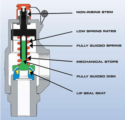
The basic spring loaded safety valve, referred to as ‘standard’ or ‘conventional’ is a simple, reliable self-acting device that provides overpressure protection.
The basic elements of the design consist of a right angle pattern valve body with the valve inlet connection, or nozzle, mounted on the pressure-containing system. The outlet connection may be screwed or flanged for connection to a piped discharge system. However, in some applications, such as compressed air systems, the safety valve will not have an outlet connection, and the fluid is vented directly to the atmosphere.
The valve inlet (or approach channel) design can be either a full-nozzle or a semi-nozzle type. A full-nozzle design has the entire ‘wetted’ inlet tract formed from one piece. The approach channel is the only part of the safety valve that is exposed to the process fluid during normal operation, other than the disc, unless the valve is discharging.
Conversely, the semi-nozzle design consists of a seating ring fitted into the body, the top of which forms the seat of the valve. The advantage of this arrangement is that the seat can easily be replaced, without replacing the whole inlet.
The disc is held against the nozzle seat (under normal operating conditions) by the spring, which is housed in an open or closed spring housing arrangement (or bonnet) mounted on top of the body. The discs used in rapid opening (pop type) safety valves are surrounded by a shroud, disc holder or huddling chamber which helps to produce the rapid opening characteristic.
The closing force on the disc is provided by a spring, typically made from carbon steel. The amount of compression on the spring is usually adjustable, using the spring adjuster, to alter the pressure at which the disc is lifted off its seat.Standards that govern the design and use of safety valves generally only define the three dimensions that relate to the discharge capacity of the safety valve, namely the flow (or bore) area, the curtain area and the discharge (or orifice) area.
Valves in which the flow area and not the curtain area determines the capacity are known as full lift valves. These valves will have a greater capacity than low lift or high lift valves.
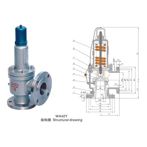
Although the principal elements of a conventional safety valve are similar, the design details can vary considerably. In general, the DIN style valves (commonly used throughout Europe) tend to use a simpler construction with a fixed skirt (or hood) arrangement whereas the ASME style valves have a more complex design that includes one or two adjustable blowdown rings. The position of these rings can be used to fine-tune the overpressure and blowdown values of the valve.
An exception to this situation is found with steel ASME specification valves, which invariably follow the recommendations of the API Recommended Practice 526, where centreline to face dimensions, and orifice sizes are listed. The orifice area series are referred to by a letter. It is common for
For example, 2" x J x 3" and 3" x J x 4" are both valves which have the same size (‘J’) orifice, but they have differing inlet and outlet sizes as shown before and after the orifice letter respectively.
When the inlet static pressure rises above the set pressure of the safety valve, the disc will begin to lift off its seat. However, as soon as the spring starts to compress, the spring force will increase; this means that the pressure would have to continue to rise before any further lift can occur, and for there to be any significant flow through the valve.
The additional pressure rise required before the safety valve will discharge at its rated capacity is called the overpressure. The allowable overpressure depends on the standards being followed and the particular application. For compressible fluids, this is normally between 3% and 10%, and for liquids between 10% and 25%.
These combined effects allow the valve to achieve its designed lift within a relatively small percentage overpressure. For compressible fluids, an additional contributory factor is the rapid expansion as the fluid volume increases from a higher to a lower pressure area. This plays a major role in ensuring that the valve opens fully within the small overpressure limit. For liquids, this effect is more proportional and subsequently, the overpressure is typically greater; 25% is common.
Once normal operating conditions have been restored, the valve is required to close again, but since the larger area of the disc is still exposed to the fluid, the valve will not close until the pressure has dropped below the original set pressure. The difference between the set pressure and this reseating pressure is known as the ‘blowdown’, and it is usually specified as a percentage of the set pressure. For compressible fluids, the blowdown is usually less than 10%, and for liquids, it can be up to 20%.
The blowdown rings found on most ASME type safety valves are used to make fine adjustments to the overpressure and blowdown values of the valves (see Figure 9.1.8). The lower blowdown (nozzle) ring is a common feature on many valves where the tighter overpressure and blowdown requirements require a more sophisticated designed solution. The upper blowdown ring is usually factory set and essentially takes out the manufacturing tolerances which affect the geometry of the huddling chamber.
The lower blowdown ring is also factory set to achieve the appropriate code performance requirements but under certain circumstances can be altered. When the lower blowdown ring is adjusted to its top position the huddling chamber volume is such that the valve will pop rapidly,
minimising the overpressure value but correspondingly requiring a greater blowdown before the valve re-seats. When the lower blowdown ring is adjusted to its lower position there is minimal restriction in the huddling chamber and a greater overpressure will be required before the valve is fully open but the blowdown value will be reduced.
For most countries, there are independent bodies who will examine the design and performance of a product range to confirm conformity with the relevant code or standard. This system of third party approval is very common for any safety related products and is often a customer requirement before purchase, or a requirement of their insurance company.
Standards relevant to safety valves vary quite considerably in format around the world, and many are sections within codes relevant to Boilers or Pressure Containing Vessels. Some will only outline performance requirements, tolerances and essential constructional detail, but give no guidance on dimensions, orifice sizes etc. Others will be related to installation and application.
For steam boiler applications there are very specific requirements for safety valve performance, demanded by national standards and often, insurance companies. Approval by an independent authority is often necessary, such as British Engine, TÜV or Lloyd’s Register.
Safety valves used in Europe are also subject to the standards associated with the Pressure Equipment Directive (PED). Being classified as ‘Safety accessories’, safety valves are considered as ‘Category 4’ equipment, which require the most demanding level of assessment within the PED regime. This can usually be met by the manufacturer having an ISO 9000 quality system and the safety valve design and performance certified by an officially recognised approval authority referred to as a ‘Notified Body’.

Safety valves and pressure relief valves are crucial for one main reason: safety. This means safety for the plant and equipment as well as safety for plant personnel and the surrounding environment.
Safety valves and pressure relief valves protect vessels, piping systems, and equipment from overpressure, which, if unchecked, can not only damage a system but potentially cause an explosion. Because these valves play such an important role, it’s absolutely essential that the right valve is used every time.
The valve size must correspond to the size of the inlet and discharge piping. The National Board specifies that the both the inlet piping and the discharge piping connected to the valve must be at least as large as the inlet/discharge opening on the valve itself.
The connection types are also important. For example, is the connection male or female? Flanged? All of these factors help determine which valve to use.
The set pressure of the valve must not exceed the maximum allowable working pressure (MAWP) of the boiler or other vessel. What this means is that the valve must open at or below the MAWP of the equipment. In turn, the MAWP of the equipment should be at least 10% greater than the highest expected operating pressure under normal circumstances.
Temperature affects the volume and viscosity of the gas or liquid flowing through the system. Temperature also helps determine the ideal material of construction for the valve. For example, steel valves can handle higher operating temperatures than valves made of either bronze or iron. Both the operating and the relieving temperature must be taken into account.
Back pressure, which may be constant or variable, is pressure on the outlet side of the pressure relief valve as a result of the pressure in the discharge system. It can affect the set pressure of the upstream valve and cause it to pop open repeatedly, which can damage the valve.
For installations with variable back pressure, valves should be selected so that the back pressure doesn’t exceed 10% of the valve set pressure. For installations with high levels of constant back pressure, a bellows-sealed valve or pilot-operated valve may be required.
Different types of service (steam, air, gas, etc.) require different valves. In addition, the valve material of construction needs to be appropriate for the service. For example, valves made of stainless steel are preferable for corrosive media.
Safety valves and relief valves must be able to relieve pressure at a certain capacity. The required capacity is determined by several factors including the geometry of the valve, the temperature of the media, and the relief discharge area.
These are just the basic factors that must be considered when selecting and sizing safety valves and relief valves. You must also consider the physical dimensions of the equipment and the plant, as well as other factors related to the environment in which the valve will operate.
Curtiss-Wright"s selection of Pressure Relief Valves comes from its outstanding product brands Farris and Target Rock. We endeavor to support the whole life cycle of a facility and continuously provide custom products and technologies. Boasting a reputation for producing high quality, durable products, our collection of Pressure Relief Valves is guaranteed to provide effective and reliable pressure relief.
While some basic components and activations in relieving pressure may differ between the specific types of relief valves, each aims to be 100% effective in keeping your equipment running safely. Our current range includes numerous valve types, from flanged to spring-loaded, threaded to wireless, pilot operated, and much more.
A pressure relief valve is a type of safety valve designed to control the pressure in a vessel. It protects the system and keeps the people operating the device safely in an overpressure event or equipment failure.
A pressure relief valve is designed to withstand a maximum allowable working pressure (MAWP). Once an overpressure event occurs in the system, the pressure relief valve detects pressure beyond its design"s specified capability. The pressure relief valve would then discharge the pressurized fluid or gas to flow from an auxiliary passage out of the system.
Below is an example of one of our pilot operated pressure relief valves in action; the cutaway demonstrates when high pressure is released from the system.
Air pressure relief valves can be applied to a variety of environments and equipment. Pressure relief valves are a safety valve used to keep equipment and the operators safe too. They"re instrumental in applications where proper pressure levels are vital for correct and safe operation. Such as oil and gas, power generation like central heating systems, and multi-phase applications in refining and chemical processing.
At Curtiss-Wright, we provide a range of different pressure relief valves based on two primary operations – spring-loaded and pilot operated. Spring-loaded valves can either be conventional spring-loaded or balanced spring-loaded.
Spring-loaded valves are programmed to open and close via a spring mechanism. They open when the pressure reaches an unacceptable level to release the material inside the vessel. It closes automatically when the pressure is released, and it returns to an average operating level. Spring-loaded safety valves rely on the closing force applied by a spring onto the main seating area. They can also be controlled in numerous ways, such as a remote, control panel, and computer program.
Pilot-operated relief valves operate by combining the primary relieving device (main valve) with self-actuated auxiliary pressure relief valves, also known as the pilot control. This pilot control dictates the opening and closing of the main valve and responds to system pressure. System pressure is fed from the inlet into and through the pilot control and ultimately into the main valve"s dome. In normal operating conditions, system pressure will prevent the main valve from opening.
The valves allow media to flow from an auxiliary passage and out of the system once absolute pressure is reached, whether it is a maximum or minimum level.
When the pressure is below the maximum amount, the pressure differential is slightly positive on the piston"s dome size, which keeps the main valve in the closed position. When system pressure rises and reaches the set point, the pilot will cut off flow to the dome, causing depressurization in the piston"s dome side. The pressure differential has reversed, and the piston will rise, opening the main valve, relieving pressure.
When the process pressure decreases to a specific pressure, the pilot closes, the dome is repressurized, and the main valve closes. The main difference between spring-loaded PRVs and pilot-operated is that a pilot-operated safety valve uses pressure to keep the valve closed.
Pilot-operated relief valves are controlled by hand and are typically opened often through a wheel or similar component. The user opens the valve when the gauge signifies that the system pressure is at an unsafe level; once the valve has opened and the pressure has been released, the operator can shut it by hand again.
Increasing pressure helps to maintain the pilot"s seal. Once the setpoint has been reached, the valve opens. This reduces leakage and fugitive emissions.
At set pressure the valve snaps to full lift. This can be quite violent on large pipes with significant pressure. The pressure has to drop below the set pressure in order for the piston to reseat.
At Curtiss-Wright we also provide solutions for pressure relief valve monitoring. Historically, pressure relief valves have been difficult or impossible to monitor. Our SmartPRV features a 2600 Series pressure relief valve accessorized with a wireless position monitor that alerts plant operators during an overpressure event, including the time and duration.
There are many causes of overpressure, but the most common ones are typically blocked discharge in the system, gas blowby, and fire. Even proper inspection and maintenance will not eliminate the occurrence of leakages. An air pressure relief valve is the only way to ensure a safe environment for the device, its surroundings, and operators.
A PRV and PSV are interchangeable, but there is a difference between the two valves. A pressure release valve gradually opens when experiencing pressure, whereas a pressure safety valve opens suddenly when the pressure hits a certain level of over pressurization. Safety valves can be used manually and are typically used for a permanent shutdown. Air pressure relief valves are used for operational requirements, and they gently release the pressure before it hits the maximum high-pressure point and circulates it back into the system.
Pressure relief valves should be subject to an annual test, one per year. The operator is responsible for carrying out the test, which should be done using an air compressor. It’s imperative to ensure pressure relief valves maintain their effectiveness over time and are checked for signs of corrosion and loss of functionality. Air pressure relief valves should also be checked before their installation, after each fire event, and regularly as decided by the operators.
Direct-acting solenoid valves have a direct connection with the opening and closing armature, whereas pilot-operated valves use of the process fluid to assist in piloting the operation of the valve.
A control valve works by varying the rate of fluid passing through the valve itself. As the valve stem moves, it alters the size of the passage and increases, decreases or holds steady the flow. The opening and closing of the valve is altered whenever the controlled process parameter does not reach the set point.
Control valves are usually at floor level or easily accessible via platforms. They are also located on the same equipment or pipeline as the measurement and downstream or flow measurements.
An industrial relief valve is designed to control or limit surges of pressure in a system, most often in fluid or compressed air system valves. It does so as a form of protection for the system and defending against instrument or equipment failure. They are usually present in clean water industries.
A PRV is often referred to as a pressure relief valve, which is also known as a PSV or pressure safety valve. They are used interchangeably throughout the industry depending on company standards.

Boiler explosions have been responsible for widespread damage to companies throughout the years, and that’s why today’s boilers are equipped with safety valves and/or relief valves. Boiler safety valves are designed to prevent excess pressure, which is usually responsible for those devastating explosions. That said, to ensure that boiler safety valves are working properly and providing adequate protection, they must meet regulatory specifications and require ongoing maintenance and periodic testing. Without these precautions, malfunctioning safety valves may fail, resulting in potentially disastrous consequences.
Boiler safety valves are activated by upstream pressure. If the pressure exceeds a defined threshold, the valve activates and automatically releases pressure. Typically used for gas or vapor service, boiler safety valves pop fully open once a pressure threshold is reached and remain open until the boiler pressure reaches a pre-defined, safe lower pressure.
Boiler relief valves serve the same purpose – automatically lowering boiler pressure – but they function a bit differently than safety valves. A relief valve doesn’t open fully when pressure exceeds a defined threshold; instead, it opens gradually when the pressure threshold is exceeded and closes gradually until the lower, safe threshold is reached. Boiler relief valves are typically used for liquid service.
There are also devices known as “safety relief valves” which have the characteristics of both types discussed above. Safety relief valves can be used for either liquid or gas or vapor service.
Nameplates must be fastened securely and permanently to the safety valve and remain readable throughout the lifespan of the valve, so durability is key.
The National Board of Boiler and Pressure Vessel Inspectors offers guidance and recommendations on boiler and pressure vessel safety rules and regulations. However, most individual states set forth their own rules and regulations, and while they may be similar across states, it’s important to ensure that your boiler safety valves meet all state and local regulatory requirements.
The National Board published NB-131, Recommended Boiler and Pressure Vessel Safety Legislation, and NB-132, Recommended Administrative Boiler and Pressure Vessel Safety Rules and Regulationsin order to provide guidance and encourage the development of crucial safety laws in jurisdictions that currently have no laws in place for the “proper construction, installation, inspection, operation, maintenance, alterations, and repairs” necessary to protect workers and the public from dangerous boiler and pressure vessel explosions that may occur without these safeguards in place.
The American Society of Mechanical Engineers (ASME) governs the code that establishes guidelines and requirements for safety valves. Note that it’s up to plant personnel to familiarize themselves with the requirements and understand which parts of the code apply to specific parts of the plant’s steam systems.
High steam capacity requirements, physical or economic constraints may make the use of a single safety valve impossible. In these cases, using multiple safety valves on the same system is considered an acceptable practice, provided that proper sizing and installation requirements are met – including an appropriately sized vent pipe that accounts for the total steam venting capacity of all valves when open at the same time.
The lowest rating (MAWP or maximum allowable working pressure) should always be used among all safety devices within a system, including boilers, pressure vessels, and equipment piping systems, to determine the safety valve set pressure.
Avoid isolating safety valves from the system, such as by installing intervening shut-off valves located between the steam component or system and the inlet.
Contact the valve supplier immediately for any safety valve with a broken wire seal, as this indicates that the valve is unsafe for use. Safety valves are sealed and certified in order to prevent tampering that can prevent proper function.
Avoid attaching vent discharge piping directly to a safety valve, which may place unnecessary weight and additional stress on the valve, altering the set pressure.
Fortunately, by understanding how relief valves work, you can solve whatever problem you’re having with the one on your water heater. In this article, we’ll review everything you should know about this valve.
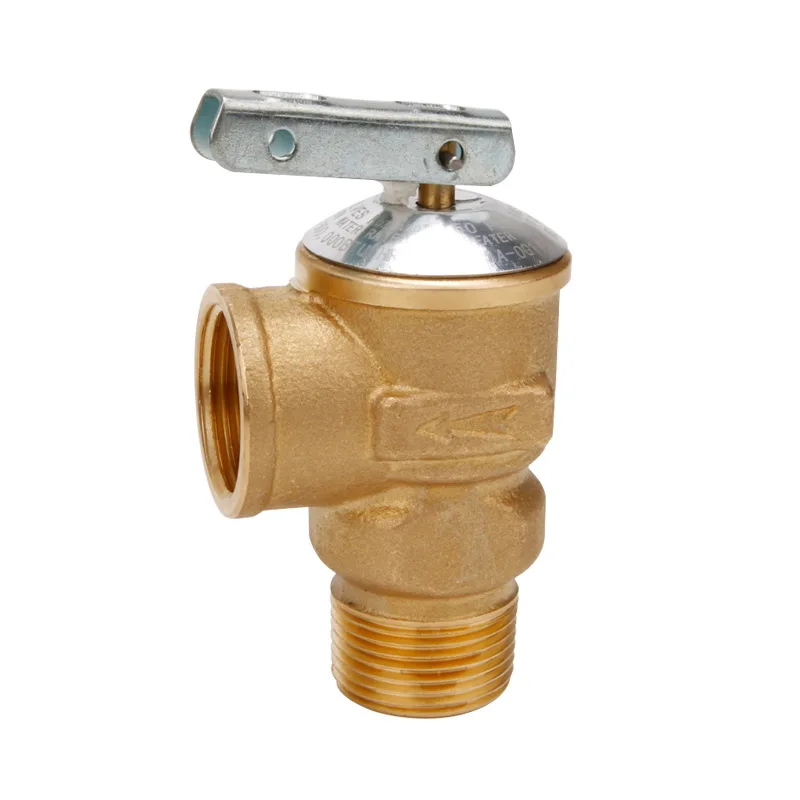
A water heater pressure relief valve, also referred to as a T&P valve, pressure relief valve, or water heater temperature valve is a safety feature that you can find on any water heater. The reason it’s there is to keep you safe in case the water pressure is too high.
Without this safety feature, your water heater could end up breaking. You could potentially end up with burns if the high water pressure is dangerously high.
This valve also ensures that there aren’t any leaks in your water heater, which would lead to low water pressure when you want to use it to wash the dishes or take a shower.
The water heater pressure relief valve is in place so that it can relieve excess pressure and temperature in a water heater if either of these is too high. Because this everyday appliance is a closed system, thermal expansion occurs in water heaters.
Here’s how it works. Whether your water heater is heated by electric elements or a gas burner, both the metal tank and the water inside expand when the hot water temperature is somewhere between 120 and 140 degrees.
However, when the temperature is 210 degrees—or the pressure is 150 pounds per inch (psi)—this is far too much pressure and heat in the water heater. If it’s the case, you should change your hot water heater temperature.
If your water heater pressure relief valve is working, this is when it will open. This releases steam and hot water from the discharge tube, making your water heater operate safely again.
On the micro-level, the functioning of this valve works like this. The relief valve itself has been set up by a professional or pre-designed to open when the temperature or pressure reaches a dangerous level.
This specific state that the water heater is in is called the “blowdown.” Usually, the “blowdown” is defined by professionals (and is used in the design or set up of the valve) as a specific pressure percentage.
The “blowdown” is usually somewhere between 2 and 20%. Once the pressure has reached the “blowdown” amount, the pressure relief valve will close again so that you can use the water heater as intended.
If you’ve been noticing any issues with your water heater pressure relief valve, then you need to know where it is on your water heater. Usually, you can find it on the top or side of this appliance. It’s a valve that’s connected to a plastic or metal discharge tube that points up.
This is for safety reasons. Everything has been done according to standards that have been mandated by plumbing codes. So if you’re having any issues with the valve, you’ll have to call a professional to have it fixed.
If you suspect there’s a problem with your water heater pressure relief valve, you can do a test. This is actually good idea if you don’t have any problems at all, as this type of maintenance will protect your water heater—and yourself.
To get started, identify where the relief valve shut off is. Usually, you can find it upon the cold water feed, which is on top of the water tank, on the right side where the inlet is.
Finally, release the level so that it quickly snaps into the original position. If it doesn’t snap quickly into this original position, then your water heater valve isn’t working and needs to be replaced.
When your water heater pressure relief valve isn’t functioning properly, it’s usually for one of to two reasons. It either sticks so that it doesn’t properly open or close, or it has a leak, which means that it’s continually dripping, lowering your water pressure.
If your valve is sticky, then it becomes stuck in a closed (downward) or open (extended position). If it’s closed, then the valve won’t be able to relieve the heat or pressure that builds up in the closed water heater system. There could be a rupture as a result.
Sometimes, you can easily fix this problem by opening and closing the valve lever a few times. However, if it continues to stick, then you’ll need to replace it.
Your water heater is leaking? Make sure that it doesn’t come from the valve before replacing it. If your pressure relief valve is leaking, then this maybe because it isn’t seated properly in the tank’s threaded opening. This is quite a common issue if you’ve recently replaced your old valve with a new one. To fix this issue with this cause, you have to take several steps.
If the lever snaps into its original position and it’s still leaking, you need to turn off the gas valve by turning it to the off position. Then, shut the water off so you can replace the valve safely.
If a water pressure issue is what is causing the water heater pressure relief valve to not work, then it might be dangerous for you to change the valve yourself. Generally speaking, it’s a good idea to hire a professional to protect yourself.
Now that we’ve reviewed everything you should know about a water heater pressure relief valve you might have realized that you need to replace your water heater valve. However, to be as safe as possible, you want to hire a professional.

Relief Valves└ Valves & Manifolds└ Hydraulics, Pneumatics, Pumps & Plumbing└ Business & IndustrialAll CategoriesAntiquesArtBabyBooks & MagazinesBusiness & IndustrialCameras & PhotoCell Phones & AccessoriesClothing, Shoes & AccessoriesCoins & Paper MoneyCollectiblesComputers/Tablets & NetworkingConsumer ElectronicsCraftsDolls & BearsMovies & TVEntertainment MemorabiliaGift Cards & CouponsHealth & BeautyHome & GardenJewelry & WatchesMusicMusical Instruments & GearPet SuppliesPottery & GlassReal EstateSpecialty ServicesSporting GoodsSports Mem, Cards & Fan ShopStampsTickets & ExperiencesToys & HobbiesTravelVideo Games & ConsolesEverything Else

In a previous article, we explored some common causes of industrial valve leakage, such as incomplete closure, damage, and valve design. These causes are properties of the valve itself, and they can result in significant leakage. However, the most common causes of safety valve leakage we see at job sites are not related to the valves themselves, but rather to improper installation and operating practices.
Most safety valves are designed, manufactured, and tested to be used vertically, meaning in the upright position with the spindle vertical. Mounting a valve horizontally can have a number of significant adverse effects:
A safety valve mounted in a non-vertical orientation may not perform as expected: the seat tightness, operation, and set pressure of the valve may be affected.
Improperly installed valves can both cause leakage and pose safety risks. To guarantee that your valves are installed correctly, and prevent damage to both the valve and the system, ensure that the installation company you use is adequately trained.
Discharge piping must be installed so that it supports its own weight and does not put any weight or strain on the valve itself. According to the National Board of Boiler and Pressure Vessel Inspectors, improperly supported discharge piping is one of the top problems that can prevent valves from operating normally. They write:
Piping that does not allow for the full range of motion.When a boiler heats up, it moves up and down, and the installation must allow both the valve and the piping to move along with it. Otherwise, there can be too much stress placed on the valve body.
Drain holes that are closed. The drain holes on spring-loaded safety valves and their discharge piping must be open when required to drain liquid from the top of the valve.
We see more problems caused by improper safety valve installation than by safety valve operation. That said, the most common operating problems we encounter are those caused by operating the valve too close to its set pressure.
For most safety valves, it is recommended that you maintain a 10% differential between the system operating pressure and the nameplate set pressure. However, seat tightness, and thus valve performance, will be better at a differential of 20%.
If you are experiencing problems with your safety valves, Allied Valve can help you identify and fix the problem so you can get back up and running as quickly and efficiently as possible.
Both pressure relief valves (PRV) and pressure safety valves (PSV) are used for process safety to relieve excess pressure. Although they’re often used interchangeably, they do have different functions and it’s important to know the difference.
If the PRV fails to maintain optimal pressure, the PSV kicks in. This valve opens quickly to avoid overpressurization when a set pressure is reached, preventing a potential safety incident.
Industrial Valve offers new PSVs and PRVs from Farris. Our Farris Authorized Service Team (FAST) can conduct pre-installation testing, install your valve, and perform regularly scheduled maintenance to keep your workflow operating at peak efficiency. Should you ever need an emergency repair, just call us – our technicians are available 24 hours a day!
VSI is your premier source for control valves, pressure relief valves, and safety relief valves. Our factory-certified experts are on-call 24/7 for repairs, testing, sizing & selection, replacement, and installation.
As your trusted source for factory-certified service solutions and consistent value and quality, VSI offers excellent customer service and world-class products and services. VSI has been focused on a legacy of quality and service since its inception in 1975 in Oklahoma City by founder Bill Campbell. Over the years, VSI has expanded its footprint to include four locations, offering service, repair, installation, and custom solutions across the United States. We offer excellent customer service, best-in-class products, and a wide variety of solutions for the process industry. VSI is the premier source for safety valves, pressure relief valves, control valves, and actuation products and services. Contact us to find out how we can help you.
Adapt almost any rotary actuator to a linear valve. Converting pneumatic actuation to electric helps increase operational efficiency and lower emissions.
VSI is a Consolidated™ Green Tag Center™ offering factory-certified repairs, installation, maintenance, and the full range of Consolidated pressure and safety relief valves. We have in-house certified technicians and product experts, and a large inventory to ensure fast delivery.
Our factory-certified and safety-trained, field service technicians are ready to be dispatched to your site. Capabilities include optimization, repair, and maintenance on pressure relief valves, safety valves, control valves, line valves, and actuation.
VSI has rebuilt our pressure relief valves here at [our processing plant] for several years now and I have always been very pleased with their service and quality of work. The work is always completed on time and we have had no reliability issues with the valves they’ve worked on. It’s always a pleasure working with VSI and I look forward to continuing the relationship.
The entire team at VSI has always been able to meet my needs and always exceeds my expectations. I have a great relationship with both the sales and service teams they are always ready to answer technical questions and provide excellent advice on ways to solve problems in the field and are always ready with solutions no matter how obscure or unusual the problem. VSI is more than ready and able to meet all my valve needs at any given moment.
VSI has been helpful in many ways, from greasing valves, valve repair, valve replacement, and training our guys as well. We can’t say enough about quotes, labor support, material delivery time, and billing. Aaron has helped us out of several jams over the years and we appreciate it.
Valve Sales Inc. provides outstanding service and support for all of our valve needs. Their dedication to quality and consistency allows our equipment to run more reliably and improves overall performance of our facility. Our goal is to provide consistent high performing products to our customers and VSI allows us to achieve this goal.
TULSA, OK – August 31, 2022 - Valve Sales Inc. (VSI), and Baker Hughes have partnered to distribute, service, and repair the complete line of Consolidated™ pressure relief valves. VSI’s service and… Read More

Industry leading pressure and safety relief valve designs with over 140 years of technical and application expertise providing custom engineered solutions for O&G, Refining, Chemical, Petrochemical, Process and Power applications. Our designs meet global and local codes and standards (API 526; ASME Section I, IV & VIII; EN ISO 4126; PED & more). Gain insight into the performance of your pressure relief valves with wireless monitoring.
meets numerous application requirements. For example. the type 1900-UM valve is capable of flowing liquid, gas or steam with no adjustment required to switch between different media with the same set pressure.
The ConsolidatedType 19000valve is ASME and PED certified. It meets and exceeds API seat tightness performance. The 19000 offers enhanced capacity and blowdown performance on many media types. In most cases, it does not require parts changes to accommodate different media.
choice for OEM and skid manufacturers requiring high-relief capacity from a small valve. The 1982 offers superior seat tightness and blowdown performance for most media applications.
The ConsolidatedType 11000Series Safety Relief Valve combines performance, quality, reliability and value into a single overpressure device. The 11000 SRV is specifically designed for the most demanding upstream and midstream oil and gas applications where safety is of prime importance.


 8613371530291