
how to calculate cdtp in safety valve made in china
(100Mbs) Over 2000 Questions and Answers. Full API document, codes, questions on each applicable Code/Section (1-2 months) prior to participate in Prometric examination. Full Training presentations for self learning. Bonus: API 510, 571 Flash Cards, PSV notes – excel files.
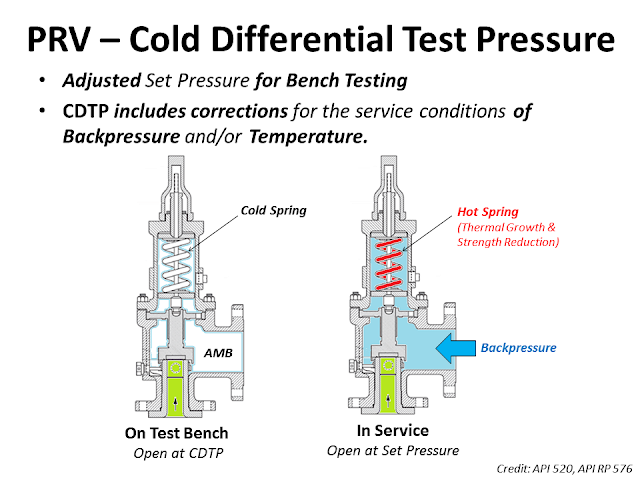
The Cold Differential Test Pressure (CDTP)of thePressure Relief Valve (PRV) is a set pressure that is adjusted to be used for the PRV (Bench Testing). Because in actual use conditions, the PRV may be affected by the Backpressure. And the operating temperature. Therefore, when testing at room temperature and without backpressure, it is necessary to adjust the set pressure to compensate for these factors. In other words, the shop test pressure = CDTP.
An example of aCold Differential Test Pressure (CDTP)with abackpressure (superimposed)effect. In this case, CDTP is equal to Set Pressure minus Backpressure.
An example of aCold Differential Test Pressure (CDTP)with different temperature compensations for use and testing. And an example ofCDTP that has been adjusted to compensate for both Backpressure (Superimposed) and temperatureeffects.
Test Stand or Test Bench is a set of equipment used for Pressure Relief Valve (PRV) in Pop Test (Set Pressure Test), Blowdown and Seat Tightness Test (Leakage Test)
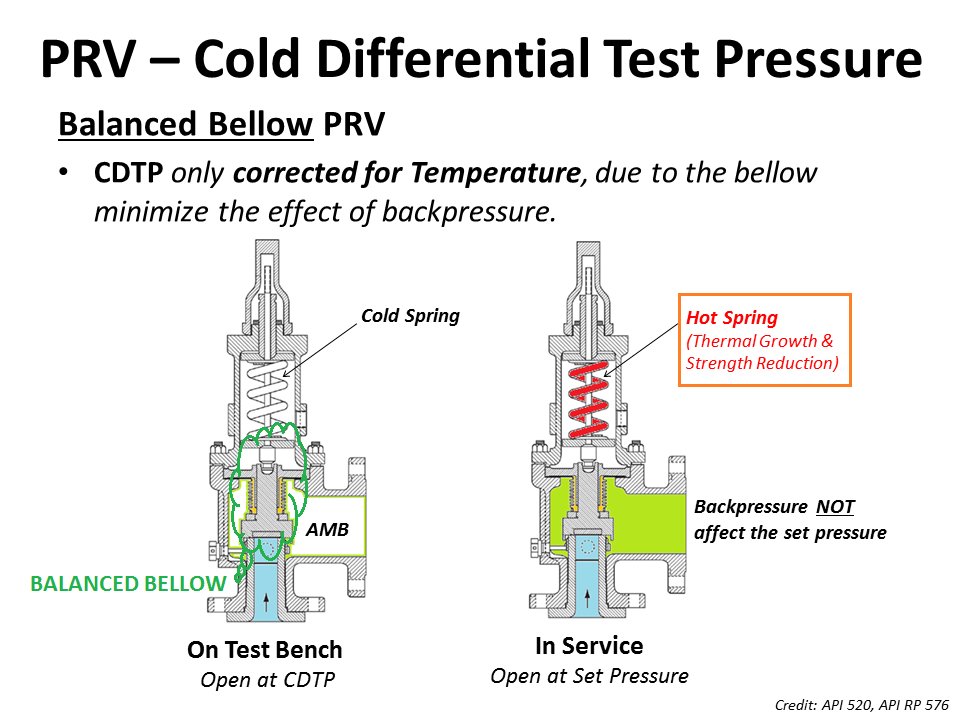
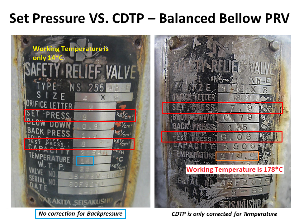
As for theBalanced Bellow Pressure Relief Valve, which has a bellowfor reducing the impact of theBackpressure, the Cold Differential Test Pressure (CDTP) of the Balanced Bellow Type PRV will compensate only for the impact of different temperatures between the Shop Test and In-service.
Proper repair of a Pressure Relief Valve starts with knowing the PRV Manufacturer and Model Number. All Pressure Relief Valves are similar, but being aware of the differences is the first step to being a qualified PRV Technician. Identification and interpretation of Nameplate Data is the basis for a proper repair.
The Manufactureris the PRV Technician"s source for information and replacement parts. Both are vital to a proper "VR" Repair. The Manufacturer or his authorized Assembler can provide the correct Maintenance Manual for Critical Dimensions and Repair Procedures as well as Original Manufacturer"s Parts for replacement.
The Model Number may be extremely long. However, each character is relevant to proper repair. It is important to determine that the PRV is the correct configuration for the application. When a PRV for Liquid service is placed in Air/Gas service, there is a high probability that the spring is the incorrect range for the service and the PRV may exhibit long blowdown when required to open due to a pressure excursion. Conversely, an Air/Gas Service PRV installed in Liquid service may have a spring that is several ranges too high for a Liquid application. The result can be inadequate lift (travel of the disc in the opening direction) during an overpressure event. This could result in reduced capacity thereby causing failure to properly protect the system. One character in the PRV Type or Model Number could make the difference between success and failure of a pressurized system.
The Model Number informs the Repair Technician of the PRV Series. This indicates suitability for the application and indicates which Maintenance Manual will be needed. Further, the Model Number typically indicates the Orifice Size of the PRV. The orifice size drives the selection of the Critical Dimensions to be measured and recorded during Inspection. Included in the Model Number may be a character that indicates the presence of a Bellows or an O-Ring Seat. Cap and Lever Designs may also be indicated in the Model Number, along with Materials (Internals & Body/Bonnet). Typically, the Model Number indicates the Inlet Pressure and Temperature Range of the PRV.
The Inlet Size, Pressure Rating and Connection (Flanged or Threaded, Male or Female) are vital for proper testing of the PRV. The PRV Technician must be able to select the proper Test Fixture for mounting the PRV on the Test Bench.
Set Pressure is necessary for selection of the proper Test Gauge and Test Bench Pressure Rating. Set Pressure and ASME Certification Mark (or Supplanted Code Stamping) lets the PRV Technician calculate the allowable ASME Code Set Pressure Tolerance.
CDTP(Cold Differential Test Pressure) may be stamped on PRVs certified to ASME Section VIII service. CDTP compensates for Elevated Temperature and/or Back Pressure. CDTP is an item of Nameplate Data that is much misunderstood. Simply put, the use of a CDTP means that the PRV Technician does not have to recreate "In-Service" conditions at the Test Bench. Elevated system temperature and/or Back Pressure can be accounted for during testing by application of the CDTP.
Capacity is important because the Units (SCFM, PPH or GPM) indicate the Test Fluid. PRVs must be tested on the appropriate fluid as indicated by the Original Nameplate Capacity.
The Year Builtor alternatively a Serial Number provides traceability to the ASME Code Edition used for construction of the PRV being repaired. Serial Numbers are not required. Rather they are permitted provided they can be traced to the year built. Serial Numbers may provide other information as well. Some Serial Numbers may indicate specific Critical Inspection Criteria or Application.
The ASME Certification Mark with the appropriate Designator or the Supplanted ASME Stamp, indicates the standard to which the PRV was built. This indicates Performance Requirements such as Set Pressure Tolerance, Seat Tightness and Pressure Testing testing requirements, as well as Material Requirements regarding Disc, Nozzle, Spring and Adjacent Sliding Surfaces (Guide & Disc Holder).
The NB Mark is not required Nameplate Data. ASME requires the PRV be capacity certified, but does not require an NB Stamping. The National Board introduced the current stylized Logo in 2001. Prior to that the letters NB were stamped on PRV Nameplates. This NB Mark indicates the PRV Design is capacity certified. This means there is a record at the National Board that can be accessed for critical information about the PRV such as Definition of Set Pressure, Adjustable or Fixed Blowdown Design and Bore Diameter. VR Holders are required to verify Nameplate Data during a repair. Verification of the PRV Capacity may require information that is available in NB-18, the Redbook, such asFlow Area, Lift and Slope or Coefficient. If the design is obsolete, the information can be obtained by contacting the National Board.
There is a wealth of information available on a PRV Nameplate and it needs to be investigated. An experienced PRV Technician knows that proper repair depends on Nameplate Data Interpretation.
The conditions at which PRV is set to operate on a test stand could be different from the actual service conditions under which a PRV is required to open in the plant.
As we had discussed the backpressure that relief valve faces in a closed system would not be present during testing in the shop and this needs to be compensated for conventional relief valves.
However as discussed above the parameter of Temperature correction factor would still be applicable to Bellows and pilot-operated relief valve if the PRV temperature is significantly different from that of ambient temperature.
Project Scenario : A Relief valve of Dresser 1900 Series (Conventional relief valve) valve is required to open at 800 Psig where the service temperature is 400°F and backpressure is 100 Psig.
Built-up back pressure is the backpressure generated due to pressure losses at the outlet of an open relief valve when it is discharging. This pressure depends on the pressure of the vent header downstream to the relief valve and the relieving flowrate which is being discharged. The built-up backpressure is the pressure in the vent header plus pressure drop in the line from relief valve to vent header, when the valve is discharging at full capacity.
For certain relief valve designs, the backpressure on the valve acts as a closing force and can affect the opening pressure for the valve. ‘Conventional’ valves are highly susceptible to this effect and hence not used in applications where high backpressure is expected. ‘Balanced Bellows’ and ‘Pilot Operated’ relief valves relatively shielded from effects of high backpressure.
For some relief valves (especially conventional type relief valves), the opening of the valve is affected by backpressure seen by the valve. If the backpressure seen by such relief valves is higher than atmospheric, then it has to be designed to open at a lower differential pressure value than the relief valve set pressure minus atmospheric pressure. However when the relief valve is tested before installation, it only sees atmospheric pressure as backpressure. Hence to open this relief valve at same differential pressure value, the set point pressure for opening the valve has to be lower than original design set point pressure. This set point value is known as cold differential test pressure (CDTP).
For pilot operated and balanced bellows type relief valves, effect of backpressure on valve opening characteristics is very low and hence CDTP is the same as the original design set point pressure value.

I think that CDTP has been used for set pressure. The data sheet should state both. Set pressure would be 25.5 but this value is stated as the operating pressure.
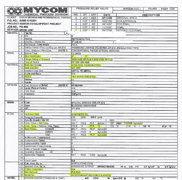
Note also. The subject Fulflo valves are Hydraulic Bypass Relief Valves and not of the API-520/-526 Pressure Relief Valve variety. A PRV data sheet has been used.
Fulflo"s technical on-line literature acknowledges that back pressure affects set pressure. You also have a non standard CL. 300 outlet flange due to high back pressure. You best check your question with the vendor.
Yes, it is a conventional piston type pressure limiting valve. Set pressure is mentioned as differential pressure. i.e, 7.03 Kg/cm2D. Constant back pressure is 18.47 Kg/cm2g. Presently the valve set in the RV shop test stand is 7.03 kg/cm2g. Our concern is, we would like to know, whether the CDTP value is correct or not? As mentioned by " The Obturator" , I think, set pressure should be mentioned as 25.5 Kg/cm2g instead of 7.03 kg/cm2g. RE: CDTP for Fulflo valve
API 520 part 1 says that the CDTP temperature correction is required when the relieving temperature exceeds 250 F however, my practice with Crosby has showed that when the OPERATING NOT RELIEVING temperature is > 150 F, the correction factor is required, u may find it in Installation manual of the relevant manufacturer i think
2) if the back pressure is constant, subtract it from the set pressure and multiply the resultant answer with the temperature correction factor (SP-BP)* TEMPERATURE CORRECTION FACTOR
3) If the valve is balanced, u have to only consider the temperature correction factors in the case of CROSBY. Not sure about the manufacturer u mentioned
for Anderson greenwood 400 series, piston type modulating valve, i couldn"t find any correction factory in the datasheet also checked with the software by increasing the both relieving and operating temperature to 250 F seems no correction is required , however, api says that u have to consult with the manufacturer RE: CDTP for Fulflo valve
“The Fulflo valves operate on differential pressures but temperature normally doesn’t affect the set pressure at which the valve will open as the valve set pressure and then relieves.”
My concern is how to calculate the CDTP. We have more than 7500 PSVs in our plant. But only these two PSVs having concern, how to calculate the CDTP. In all other PSVs data sheet, set pressure is mentioned in kg/cm2g engineering unit, but in these two pzvs, set pressure is kg/cm2D (Differential pressure).
At present, we have mentioned the CDTP as 7.03 kg/cm2g. As we considered as Set pressure is 25.5 kg/cm2g & constant back pressure is 18.47 kg/cm2g. As mentioned above by " The Obturator" , set pressure should be mentioned as 25.5 Kg/cm2g instead of 7.03 kg/cm2g.
Thats a manufacturer chart not API-520. My earlier point is that API-520 does not give a lower/start limit as suggested (in may have done in an earlier API-520 revision), but to obtain from manufacturer. In the case of FulFlo they have answered that they do not compensate.
Regarding also your attached manufacturers chart. It is incomplete. For example, for Crosby, that is the chart for J series (JOS-E/JBS-E). For steam and other valve types the compensation chart is different. The chart also fails to advise that the compensation factor applies to operating temperatured (too many users have taken relief temperature - note Tai incorrectly state this - see API-520).
There have been some substantial changes to the relevant specifications in the last 20 years, I do notice a lot of people seem to be using services like Scribd for access to old documents which exacerbates this problem.
The temperature compensation factor should be outlined in the manufacturers IOM, The Obturator correctly points out that this should be based on operating not relieving temperature as the impact of the thermal effect will not be observed unless the spring is normally exposed to the high temperature. RE: CDTP for Fulflo valve
I am having API-520 9th edition 2014(find attached screen shot). Regarding the temperature correction factor, we are still using the updated chart from the respective pzv manufacturer. Yes, i agree that the correction factor chart is incomplete, i just copied & send to you for the easy reference only. WE are having every pzv manufacture updated IOM.
Find attached 2nd screen shot for the discussion with Crosby (Emerson) team in Sept 2019. Just i want to inform you that we are aware about the latest edition of API 520.
The last revision of API Standard 520, Part I, Ninth Edition (4.2.3 Cold Differential Test Pressure) provides clarity to the possible ambiguity regarding “service conditions” definition as follows:
“4.2.3.3 The temperature used for the correction factor should be based on the temperature at the inlet to the relief valve at its normal service (nonrelieving) conditions
and also used in sizing software programs (ie: PRV2SIZE, etc.) are based on operating temperature at the valve normal service (nonrelieving) conditions.
As per previous Saudi Aramco pzv procedure, for Crosby PZVs, relieving temperature will be considered as operating temperature, while calculating the temperature compensation. May be you have noticed the highlighted portion from the procedure screen shot. Based on API update, it was updated. Now for any manufacturer pzvs, operating temperature will be considered for CDTP.


 8613371530291