
how to calculate cdtp in safety valve price
A safety valve is a valve that acts as a protection of equipment from exploding or damaging and it is mainly installed in pressure vessels such as chemical plants, electric power boilers, and gas storage tanks.
Safety Relief Valve is a type of valve that automatically actuates when the pressure of inlet side of the valve increases to a predetermined pressure, to open the valve disc and discharge the fluid (steam or gas); and when the pressure decreases to the prescribed value, to close the valve disc again.
There are a number of reasons why the pressure in a vessel or equipment can exceed a predetermined limit. The most common are: Blocked outlet; Exposure to external fire, often referred to as “Fire Case”; Thermal expansion of fluid; Abnormal process conditions (Chemical reaction); Cooling system failure; Heat exchanger tube rupture; Pipework component failure; Control Valve failure, etc.
Each of the above-listed events may occur individually or simultaneously. Every cause of over-pressure will create a different mass or volume flow to be discharged. For e.g. small mass flow for thermal expansion and large mass flow in case of a chemical reaction. It is the process engineer’s responsibility to determine the most worst-case scenario for the sizing and selection of a suitable pressure safety device.
Relief valve: A spring-loaded pressure-relief valve actuated by the static pressure upstream of the valve. The valve opens normally in proportion to the pressure increase over the opening pressure. A relief valve is used primarily with incompressible fluids such as any Liquid.
Safety valve: A spring-loaded pressure-relief valve actuated by the static pressure upstream of the valve and characterized by rapid opening or pop action. A safety valve is normally used with compressible fluids such as any Gases, Steam.
The terms full lift, high lift, and low lift refer to the amount of travel the disc undergoes as it moves from its closed position to the position required to produce the certified discharge capacity, and how this affects the discharge capacity of the valve.
A full lift safety valve is one in which the disc lifts sufficiently so that the curtain area no longer influences the discharge area. The discharge area, and therefore the capacity of the valve are subsequently determined by the bore area. This occurs when the disc lifts a distance of at least a quarter of the bore diameter. A full lift conventional safety valve is often the best choice for general steam applications.
The disc of a high lift safety valve lifts a distance of at least 1/12th of the bore diameter. This means that the curtain area, and ultimately the position of the disc, determines the discharge area. The discharge capacities of high lift valves tend to be significantly lower than those of full lift valves, and for a given discharge capacity, it is usually possible to select a full lift valve that has a nominal size several times smaller than a corresponding high lift valve, which usually incurs cost advantages. Furthermore, high lift valves tend to be used on compressible fluids where their action is more proportional.
In low lift valves, the disc only lifts a distance of 1/24th of the bore diameter. The discharge area is determined entirely by the position of the disc, and since the disc only lifts a small amount, the capacities tend to be much lower than those of full or high lift valves.
A conventional safety Relief Valve is a pressure Relief Valve which has its spring housing vented to the discharge side of the Valve. The operational characteristics (opening pressure, closing pressure, and relieving capacity) are directly affected by changes of the back pressure on the Valve.
A balanced safety Relief Valve is a pressure Relief Valve which incorporates means of minimizing the effect of back pressure on the operational characteristics (opening pressure, closing pressure, and relieving capacity).
A pilot-operated pressure Relief Valve is a pressure Relief Valve in which the major relieving device is combined with and is controlled by a self-actuated auxiliary pressure Relief Valve.
A power-actuated pressure Relief Valve is a pressure Relief Valve in which the major relieving device is combined with and controlled by a device requiring an external source of energy.
A temperature-actuated pressure Relief Valve is a pressure Relief Valve that may be actuated by external or internal temperature or by pressure on the inlet side.
A vacuum Relief Valve is a pressure relief device designed to admit fluid to prevent an excessive internal vacuum; it is designed to reclose and prevent further flow of fluid after normal conditions have been restored.
Accumulation: The pressure increases over the MAWP of the vessel, expressed in pressure units, or as a percentage of MAWP or design pressure. Maximum allowable accumulations are established by applicable codes for emergency operating and fire contingencies.
Actual discharge area or actual orifice area: The area of a pressure-relief valve (PRV) is the minimum net area that determines the flow through a valve.
Backpressure: The pressure that exists at the outlet of a pressure-relief device as a result of the pressure in the discharge system. Backpressure is the sum of the superimposed and built-up backpressures.
Superimposed backpressure: The static pressure that exists at the outlet of a pressure-relief device at the time the device is required to operate. Superimposed backpressure is the result of pressure in the discharge system coming from other sources and may be constant or variable.
Built-up backpressure: The increase in pressure at the outlet of a pressure-relief device that develops as a result of flow after the pressure-relief device opens.
Blowdown: The difference between the set pressure and the closing pressure of a pressure-relief valve, expressed as a percentage of the set pressure or in pressure units.
Closing pressure: The value of decreasing inlet static pressure at which the valve disc re-establishes contact with the seat or at which lift becomes zero as determined by seeing, feeling, or hearing.
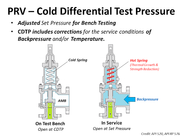
Cold differential test pressure (CDTP): The pressure at which a pressure-relief valve is adjusted to open on the test stand. The CDTP includes corrections for the service conditions of backpressure or temperature or both.
Curtain area: The area of the cylindrical or conical discharge opening between the seating surfaces above the nozzle seat created by the lift of the disc.
Opening pressure: The value of increasing inlet static pressure at which there is a measurable lift of the disc or at which discharge of the fluid becomes continuous, as determined by seeing, feeling, or hearing.
Overpressure: The pressure increases over the set pressure of the relieving device. Overpressure is expressed in pressure units or as a percentage of set pressure. Overpressure is the same as accumulation only when the relieving device is set to open at the MAWP of the vessel.
Pressure-relief device (PRD): A device actuated by inlet static pressure and designed to open during an emergency or abnormal conditions to prevent a rise of internal fluid pressure in excess of specified design value. The device also may be designed to prevent an excessive internal vacuum. The device may be a pressure-relief valve, a non-reclosing pressure-relief device, or a vacuum relief valve.
Conventional pressure-relief valve: A spring-loaded pressure-relief valve whose operational characteristics are directly affected by changes in the backpressure.
Balanced pressure-relief valve: A spring-loaded pressure-relief valve that incorporates a bellows or other means for minimizing the effect of backpressure on the operational characteristics of the valve.
Modulating pressure-relief valve: A pressure-relief valve that opens and flows in proportion to the inlet pressure for some or all parts of the valve’s operating range from set pressure to overpressure at full lift.
Pilot-operated pressure-relief valve: A pressure-relief valve in which the major relieving device or main valve is combined with and controlled by a self-actuated auxiliary pressure-relief valve (pilot).
Built-up back pressure is the backpressure generated due to pressure losses at the outlet of an open relief valve when it is discharging. This pressure depends on the pressure of the vent header downstream to the relief valve and the relieving flowrate which is being discharged. The built-up backpressure is the pressure in the vent header plus pressure drop in the line from relief valve to vent header, when the valve is discharging at full capacity.
For certain relief valve designs, the backpressure on the valve acts as a closing force and can affect the opening pressure for the valve. ‘Conventional’ valves are highly susceptible to this effect and hence not used in applications where high backpressure is expected. ‘Balanced Bellows’ and ‘Pilot Operated’ relief valves relatively shielded from effects of high backpressure.
For some relief valves (especially conventional type relief valves), the opening of the valve is affected by backpressure seen by the valve. If the backpressure seen by such relief valves is higher than atmospheric, then it has to be designed to open at a lower differential pressure value than the relief valve set pressure minus atmospheric pressure. However when the relief valve is tested before installation, it only sees atmospheric pressure as backpressure. Hence to open this relief valve at same differential pressure value, the set point pressure for opening the valve has to be lower than original design set point pressure. This set point value is known as cold differential test pressure (CDTP).
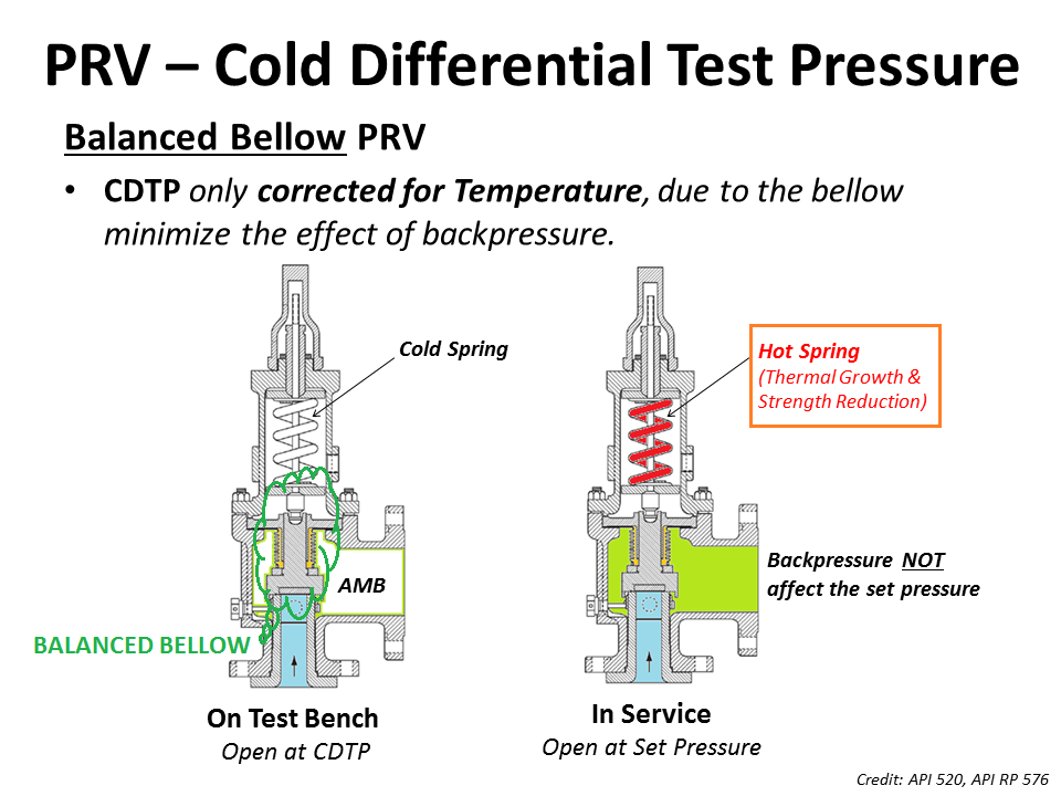
For pilot operated and balanced bellows type relief valves, effect of backpressure on valve opening characteristics is very low and hence CDTP is the same as the original design set point pressure value.
Taylor Valve Technology® is a manufacturer leader in high-quality industrial valves. We deliver safety relief, high-pressure relief, and back pressure relief valves. Our wide array of choke and control valves and pilot-operated valve products are second to none. Products are designed for demanding industrial needs, meeting quality API and ASME Code requirements. High-demand oil & gas industry, chemical plants, power generators, and the processing industry depend on our valves for consistency and durability. Get effective flow control of liquid, steam, and gas. Valves ship from the Taylor Valve Technology, Inc. United States facility. Delivering worldwide, you can depend on quick turnaround times.

(100Mbs) Over 2000 Questions and Answers. Full API document, codes, questions on each applicable Code/Section (1-2 months) prior to participate in Prometric examination. Full Training presentations for self learning. Bonus: API 510, 571 Flash Cards, PSV notes – excel files.
The Cold Differential Test Pressure (CDTP)of thePressure Relief Valve (PRV) is a set pressure that is adjusted to be used for the PRV (Bench Testing). Because in actual use conditions, the PRV may be affected by the Backpressure. And the operating temperature. Therefore, when testing at room temperature and without backpressure, it is necessary to adjust the set pressure to compensate for these factors. In other words, the shop test pressure = CDTP.
An example of aCold Differential Test Pressure (CDTP)with abackpressure (superimposed)effect. In this case, CDTP is equal to Set Pressure minus Backpressure.
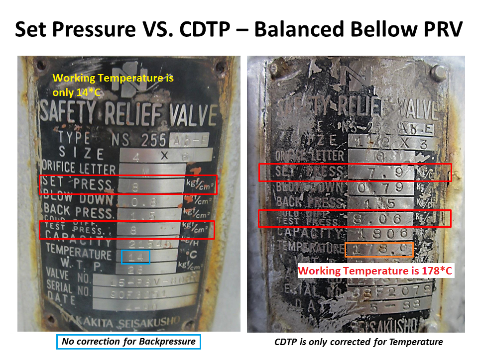
An example of aCold Differential Test Pressure (CDTP)with different temperature compensations for use and testing. And an example ofCDTP that has been adjusted to compensate for both Backpressure (Superimposed) and temperatureeffects.
Test Stand or Test Bench is a set of equipment used for Pressure Relief Valve (PRV) in Pop Test (Set Pressure Test), Blowdown and Seat Tightness Test (Leakage Test)
As for theBalanced Bellow Pressure Relief Valve, which has a bellowfor reducing the impact of theBackpressure, the Cold Differential Test Pressure (CDTP) of the Balanced Bellow Type PRV will compensate only for the impact of different temperatures between the Shop Test and In-service.


 8613371530291