
how to change pressure cooker safety valve manufacturer

This website is using a security service to protect itself from online attacks. The action you just performed triggered the security solution. There are several actions that could trigger this block including submitting a certain word or phrase, a SQL command or malformed data.
New: A brand-new, unused, unopened, undamaged item in its original packaging (where packaging is applicable). Packaging should be the same as what is found in a retail store, unless the item is handmade or was packaged by the manufacturer in non-retail packaging, such as an unprinted box or plastic bag. See the seller"s listing for full details.See all condition definitionsopens in a new window or tab

The pressure relief valve is a warning device that is designed to provide both visual and audio signals to indicate that the vent pipe has been blocked and is no longer regulating pressure and there is excessive pressure in the cooker.
This part is for use only with the models 0136511 Presto® 6-Quart Stainless Steel Pressure Cooker and 0137005 Presto® 8-Quart Stainless Steel Pressure Cooker.

This website is using a security service to protect itself from online attacks. The action you just performed triggered the security solution. There are several actions that could trigger this block including submitting a certain word or phrase, a SQL command or malformed data.

A safety valve is a valve that acts as a fail-safe. An example of safety valve is a pressure relief valve (PRV), which automatically releases a substance from a boiler, pressure vessel, or other system, when the pressure or temperature exceeds preset limits. Pilot-operated relief valves are a specialized type of pressure safety valve. A leak tight, lower cost, single emergency use option would be a rupture disk.
Safety valves were first developed for use on steam boilers during the Industrial Revolution. Early boilers operating without them were prone to explosion unless carefully operated.
Vacuum safety valves (or combined pressure/vacuum safety valves) are used to prevent a tank from collapsing while it is being emptied, or when cold rinse water is used after hot CIP (clean-in-place) or SIP (sterilization-in-place) procedures. When sizing a vacuum safety valve, the calculation method is not defined in any norm, particularly in the hot CIP / cold water scenario, but some manufacturers
The earliest and simplest safety valve was used on a 1679 steam digester and utilized a weight to retain the steam pressure (this design is still commonly used on pressure cookers); however, these were easily tampered with or accidentally released. On the Stockton and Darlington Railway, the safety valve tended to go off when the engine hit a bump in the track. A valve less sensitive to sudden accelerations used a spring to contain the steam pressure, but these (based on a Salter spring balance) could still be screwed down to increase the pressure beyond design limits. This dangerous practice was sometimes used to marginally increase the performance of a steam engine. In 1856, John Ramsbottom invented a tamper-proof spring safety valve that became universal on railways. The Ramsbottom valve consisted of two plug-type valves connected to each other by a spring-laden pivoting arm, with one valve element on either side of the pivot. Any adjustment made to one of valves in an attempt to increase its operating pressure would cause the other valve to be lifted off its seat, regardless of how the adjustment was attempted. The pivot point on the arm was not symmetrically between the valves, so any tightening of the spring would cause one of the valves to lift. Only by removing and disassembling the entire valve assembly could its operating pressure be adjusted, making impromptu "tying down" of the valve by locomotive crews in search of more power impossible. The pivoting arm was commonly extended into a handle shape and fed back into the locomotive cab, allowing crews to "rock" both valves off their seats to confirm they were set and operating correctly.
Safety valves also evolved to protect equipment such as pressure vessels (fired or not) and heat exchangers. The term safety valve should be limited to compressible fluid applications (gas, vapour, or steam).
For liquid-packed vessels, thermal relief valves are generally characterized by the relatively small size of the valve necessary to provide protection from excess pressure caused by thermal expansion. In this case a small valve is adequate because most liquids are nearly incompressible, and so a relatively small amount of fluid discharged through the relief valve will produce a substantial reduction in pressure.
Flow protection is characterized by safety valves that are considerably larger than those mounted for thermal protection. They are generally sized for use in situations where significant quantities of gas or high volumes of liquid must be quickly discharged in order to protect the integrity of the vessel or pipeline. This protection can alternatively be achieved by installing a high integrity pressure protection system (HIPPS).
In the petroleum refining, petrochemical, chemical manufacturing, natural gas processing, power generation, food, drinks, cosmetics and pharmaceuticals industries, the term safety valve is associated with the terms pressure relief valve (PRV), pressure safety valve (PSV) and relief valve.
The generic term is Pressure relief valve (PRV) or pressure safety valve (PSV). PRVs and PSVs are not the same thing, despite what many people think; the difference is that PSVs have a manual lever to open the valve in case of emergency.
Relief valve (RV): an automatic system that is actuated by the static pressure in a liquid-filled vessel. It specifically opens proportionally with increasing pressure
Pilot-operated safety relief valve (POSRV): an automatic system that relieves on remote command from a pilot, to which the static pressure (from equipment to protect) is connected
Low pressure safety valve (LPSV): an automatic system that relieves static pressure on a gas. Used when the difference between the vessel pressure and the ambient atmospheric pressure is small.
Vacuum pressure safety valve (VPSV): an automatic system that relieves static pressure on a gas. Used when the pressure difference between the vessel pressure and the ambient pressure is small, negative and near to atmospheric pressure.
Low and vacuum pressure safety valve (LVPSV): an automatic system that relieves static pressure on a gas. Used when the pressure difference is small, negative or positive and near to atmospheric pressure.
In most countries, industries are legally required to protect pressure vessels and other equipment by using relief valves. Also, in most countries, equipment design codes such as those provided by the ASME, API and other organizations like ISO (ISO 4126) must be complied with. These codes include design standards for relief valves and schedules for periodic inspection and testing after valves have been removed by the company engineer.
Today, the food, drinks, cosmetics, pharmaceuticals and fine chemicals industries call for hygienic safety valves, fully drainable and Cleanable-In-Place. Most are made of stainless steel; the hygienic norms are mainly 3A in the USA and EHEDG in Europe.
The first safety valve was invented by Denis Papin for his steam digester, an early pressure cooker rather than an engine.steelyard" lever a smaller weight was required, also the pressure could easily be regulated by sliding the same weight back and forth along the lever arm. Papin retained the same design for his 1707 steam pump.Greenwich in 1803, one of Trevithick"s high-pressure stationary engines exploded when the boy trained to operate the engine left it to catch eels in the river, without first releasing the safety valve from its working load.
Although the lever safety valve was convenient, it was too sensitive to the motion of a steam locomotive. Early steam locomotives therefore used a simpler arrangement of weights stacked directly upon the valve. This required a smaller valve area, so as to keep the weight manageable, which sometimes proved inadequate to vent the pressure of an unattended boiler, leading to explosions. An even greater hazard was the ease with which such a valve could be tied down, so as to increase the pressure and thus power of the engine, at further risk of explosion.
Although deadweight safety valves had a short lifetime on steam locomotives, they remained in use on stationary boilers for as long as steam power remained.
Weighted valves were sensitive to bouncing from the rough riding of early locomotives. One solution was to use a lightweight spring rather than a weight. This was the invention of Timothy Hackworth on his leaf springs.
These direct-acting spring valves could be adjusted by tightening the nuts retaining the spring. To avoid tampering, they were often shrouded in tall brass casings which also vented the steam away from the locomotive crew.
The Salter coil spring spring balance for weighing, was first made in Britain by around 1770.spring steels to make a powerful but compact spring in one piece. Once again by using the lever mechanism, such a spring balance could be applied to the considerable force of a boiler safety valve.
The spring balance valve also acted as a pressure gauge. This was useful as previous pressure gauges were unwieldy mercury manometers and the Bourdon gauge had yet to be invented.
Paired valves were often adjusted to slightly different pressures too, a small valve as a control measure and the lockable valve made larger and permanently set to a higher pressure, as a safeguard.Sinclair for the Eastern Counties Railway in 1859, had the valve spring with pressure scale behind the dome, facing the cab, and the locked valve ahead of the dome, out of reach of interference.
In 1855, John Ramsbottom, later locomotive superintendent of the LNWR, described a new form of safety valve intended to improve reliability and especially to be tamper-resistant. A pair of plug valves were used, held down by a common spring-loaded lever between them with a single central spring. This lever was characteristically extended rearwards, often reaching into the cab on early locomotives. Rather than discouraging the use of the spring lever by the fireman, Ramsbottom"s valve encouraged this. Rocking the lever freed up the valves alternately and checked that neither was sticking in its seat.
A drawback to the Ramsbottom type was its complexity. Poor maintenance or mis-assembly of the linkage between the spring and the valves could lead to a valve that no longer opened correctly under pressure. The valves could be held against their seats and fail to open or, even worse, to allow the valve to open but insufficiently to vent steam at an adequate rate and so not being an obvious and noticeable fault.Rhymney Railway, even though the boiler was almost new, at only eight months old.
Naylor valves were introduced around 1866. A bellcrank arrangement reduced the strain (percentage extension) of the spring, thus maintaining a more constant force.L&Y & NER.
All of the preceding safety valve designs opened gradually and had a tendency to leak a "feather" of steam as they approached "blowing-off", even though this was below the pressure. When they opened they also did so partially at first and didn"t vent steam quickly until the boiler was well over pressure.
The quick-opening "pop" valve was a solution to this. Their construction was simple: the existing circular plug valve was changed to an inverted "top hat" shape, with an enlarged upper diameter. They fitted into a stepped seat of two matching diameters. When closed, the steam pressure acted only on the crown of the top hat, and was balanced by the spring force. Once the valve opened a little, steam could pass the lower seat and began to act on the larger brim. This greater area overwhelmed the spring force and the valve flew completely open with a "pop". Escaping steam on this larger diameter also held the valve open until pressure had dropped below that at which it originally opened, providing hysteresis.
These valves coincided with a change in firing behaviour. Rather than demonstrating their virility by always showing a feather at the valve, firemen now tried to avoid noisy blowing off, especially around stations or under the large roof of a major station. This was mostly at the behest of stationmasters, but firemen also realised that any blowing off through a pop valve wasted several pounds of boiler pressure; estimated at 20 psi lost and 16 lbs or more of shovelled coal.
Pop valves derived from Adams"s patent design of 1873, with an extended lip. R. L. Ross"s valves were patented in 1902 and 1904. They were more popular in America at first, but widespread from the 1920s on.
Although showy polished brass covers over safety valves had been a feature of steam locomotives since Stephenson"s day, the only railway to maintain this tradition into the era of pop valves was the GWR, with their distinctive tapered brass safety valve bonnets and copper-capped chimneys.
Developments in high-pressure water-tube boilers for marine use placed more demands on safety valves. Valves of greater capacity were required, to vent safely the high steam-generating capacity of these large boilers.Naylor valve) became more critical.distilled feedwater and also a scouring of the valve seats, leading to wear.
High-lift safety valves are direct-loaded spring types, although the spring does not bear directly on the valve, but on a guide-rod valve stem. The valve is beneath the base of the stem, the spring rests on a flange some height above this. The increased space between the valve itself and the spring seat allows the valve to lift higher, further clear of the seat. This gives a steam flow through the valve equivalent to a valve one and a half or twice as large (depending on detail design).
The Cockburn Improved High Lift design has similar features to the Ross pop type. The exhaust steam is partially trapped on its way out and acts on the base of the spring seat, increasing the lift force on the valve and holding the valve further open.
To optimise the flow through a given diameter of valve, the full-bore design is used. This has a servo action, where steam through a narrow control passage is allowed through if it passes a small control valve. This steam is then not exhausted, but is passed to a piston that is used to open the main valve.
There are safety valves known as PSV"s and can be connected to pressure gauges (usually with a 1/2" BSP fitting). These allow a resistance of pressure to be applied to limit the pressure forced on the gauge tube, resulting in prevention of over pressurisation. the matter that has been injected into the gauge, if over pressurised, will be diverted through a pipe in the safety valve, and shall be driven away from the gauge.
There is a wide range of safety valves having many different applications and performance criteria in different areas. In addition, national standards are set for many kinds of safety valves.
Safety valves are required on water heaters, where they prevent disaster in certain configurations in the event that a thermostat should fail. Such a valve is sometimes referred to as a "T&P valve" (Temperature and Pressure valve). There are still occasional, spectacular failures of older water heaters that lack this equipment. Houses can be leveled by the force of the blast.
Pressure cookers are cooking pots with a pressure-proof lid. Cooking at pressure allows the temperature to rise above the normal boiling point of water (100 degrees Celsius at sea level), which speeds up the cooking and makes it more thorough.
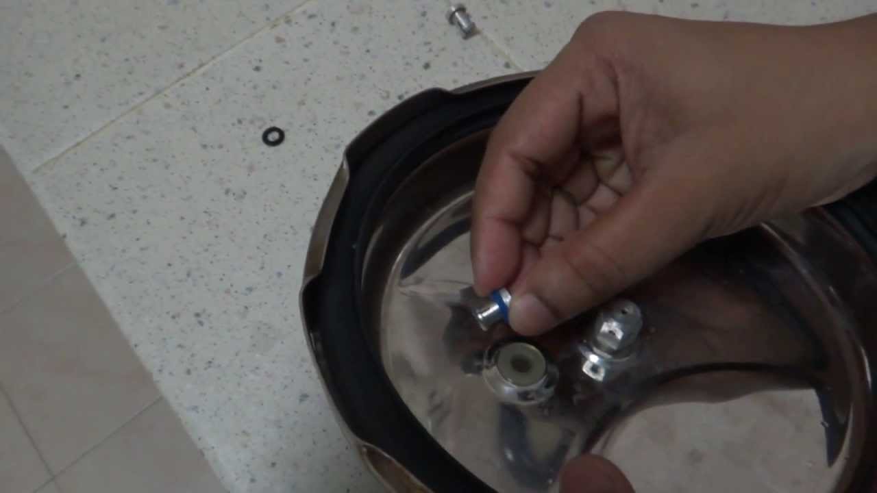
Pressure cookers usually have two safety valves to prevent explosions. On older designs, one is a nozzle upon which a weight sits. The other is a sealed rubber grommet which is ejected in a controlled explosion if the first valve gets blocked. On newer generation pressure cookers, if the steam vent gets blocked, a safety spring will eject excess pressure and if that fails, the gasket will expand and release excess pressure downwards between the lid and the pan. Also, newer generation pressure cookers have a safety interlock which locks the lid when internal pressure exceeds atmospheric pressure, to prevent accidents from a sudden release of very hot steam, food and liquid, which would happen if the lid were to be removed when the pan is still slightly pressurised inside (however, the lid will be very hard or impossible to open when the pot is still pressurised).
These figures are based on two measurements, a drop from 225 psi to 205 psi for an LNER Class V2 in 1952 and a smaller drop of 10 psi estimated in 1953 as 16 lbs of coal.
"Trial of HMS Rattler and Alecto". April 1845. The very lowest pressure exhibited "when the screw was out of the water" (as the opponents of the principle term it) was 34 lb, ranging up to 60 lb., on Salter"s balance.

Such a valve assembly is known from German laying-open print DOS No. 2,606,676. The pressure relief means thereof consists of a check valve which also serves as a safety valve. It has a valve housing of a resilient material which is fitted into a hole in the cover in the vicinity of the cooking valve aperture. The closure body is designed as a shaft-shaped valve body, transverses the valve opening and supports two spaced valve disks inside the cover as well as a dome-shaped head outside the cover. The head abuts against the valve opening in the pressureless state. As the pressure builds up in the pressure-cooker, however, the valve body is lifted and the upper valve disk closes off the valve opening internally so that the pressure in the cooker can build up. When the pressure becomes excessive, the upper valve disk can move outwardly through the valve opening of the valve housing. This allows steam to escape through the valve opening. The second valve disk preventing the valve body from being blown off the cooker although it does not obstruct the escape of steam. The cooking valve usually comprises a spring-loaded valve and a displaceable pressure indicator for the cooker which is located therein and is also spring-loaded. The springs press against the interior of a cap which is adapted to be screwed on to the valve housing. In the known valve assembly, the cap of the cooking valve has an asymmetrical design on the underside facing towards the cooker cover. It features a guide bevel at this location which reduces its clearance height. In the normal cooking position, the area with the maximum inner clearance height overlaps or overlies the check valve. When the cap is screwed off, the area with a minimum clearance height comes to lie above the check valve over which it can move without obstruction when the head of the check valve abuts against the outer side of the valve seat in the completely pressureless state. If the check valve has closed due to the internal build-up of pressure in the cooker, ie if the upper valve disk abuts against the valve seat, the guide bevel presses the valve body of the check valve downwardly and steam can escape through the check valve. The pressure in the cooker is relieved, whilst the person using the cooker is warned simultaneously by the sound of the escaping steam not to unscrew the cap any farther. If the valve body has been raised only slightly owing to a slight superpressure in the cooker, eg at the onset of pressure build-up, an additional stop which projects into the clearance height prevents the cap from being rotated any farther.
The known valve assembly is expensive to manufacture, since it requires a valve housing and a valve body for the pressure relief means. These parts are expensive to manufacture and to assemble. The cap of the cooking valve is also expensive to produce owing to its asymmetrical shape, and the dimensions of the guide bevel as well as the region of reduced clearance height must be kept within a narrow tolerance range: the valve body must be pressed downwardly to open the valve on the one hand, although on the othe hand this must not be so far that the valve head closes the opening externally. Another drawback is that when the cap is rotated into the open position, the stop jams the head of the valve body and this cannot return to its original position, even when the cooker is not under pressure, until the cap has been turned back somewhat. When the check valve functions as a safety valve, the valve disk cannot automatically turn back any longer due to the valve opening. The cap cannot be screwed off over the projecting valve body either. This makes it impossible to gain access to the valve body and return it to the normal position. Yet another disadvantage is that the valve body of the check valve can only be cleaned thoroughly--quite essential for proper sealing--if it has been snapped out of the valve disk. Since this is complicated and troublesome, such cleaning is frequently postponed or forgotten completely.
A valve assembly comprising a pressure relief means disposed adjacent to the cooking valve is also known from German utility model No. 7,624,730. The pressure relief means is designed as a safety valve in the form of a check valve. The cap of the cooking valve has indents on the periphery thereof. Both valves are spatially associated with one another such that the valve body can be raised adjacent to such an indent only when the cap is in certain positions. The check valve can be closed and pressure built up in the cooker only in this position. When the valve body is in the raised position, ie when pressure has built up in the cooker, the valve body in turn locks the cap of the cooking valve which cannot be rotated. Hence, the vent opening cannot be opened by adjusting the cap. This known valve assembly, which therefore does not correspond to the preamble of the present invention, is expensive to manufacture due to the design of the check valve. It is also difficult to clean, since the steam is dissipated to one side through a cavity in the cooking valve beneath the cap when the safety valve responds to excessive pressure. These cavities are difficult to reach, even after the cap has been removed. Furthermore, the valve body cannot be turned back into its original position until after the safety valve has responded and the excess pressure has been vented off. Only then can the cap be removed from the cooking valve.
The object of the present invention is to provide a valve assembly according to the preamble of the claim which is economical to manufacture, easy to clean and simple to operate in all modes of operation.
The construction of the closure body as a seal disposed on the cap makes it possible to design the vent opening in the form of a simple hole in the cover without any valve housing. Such a hole can be produced during one and the same operation as the hole for the cooking valve. It is easy to clean. The arrangement of the associated seal in the cap gives rise to a constructional design which is simple and easy to clean. This construction of the pressure relief means is made possible by the recognition that the vent opening need only be open to relieve the pressure. An open valve is unnecessary prior to a pressure build-up, since the air being heated up can escape by way of the conventional sealing rings between the pressure-cooker and the cover until the sealing ring abuts sealingly against the cover and cooker wall due to the build-up of pressure. In the pressure relief means in accordance with the invention, the co-operation of the seal and the vent opening permits steam to escape even when the cap is moved minimally towards the venting position. The pressure in the cooker decreases immediately. Moreover, the co-action of the venting opening and the seal generates a warning sound which warns the cook not to opening the cooking valve while the cooker is still under pressure. If there is no seal in the cap, no pressure will build up in the cooker at all.
The seal can advantageously consist of a material which is so resilient that it sealingly closes the vent opening at normal cooking pressure and permits pressure to be vented should it become eccessive. The pressure relief means thus functions as a safety valve as well.
In a preferred embodiment, the seal is designed in an annular shape. It is impossible to insert a ring improperly. The opening is always covered irrespectively of the angular position of the cap in the cooking position.
The annular seal advantageously has an internal diameter which is smaller than the external diameter of the cap section it surrounds. The annular seal is thus seated in the cap region in such a way that it can be neither twisted nor lost. Dirt cannot readily collect between the cap and the annular seal so that the seal does not have to be removed every time the cooker is cleaned.
FIG. 1 indicates the cover 1 of a pressure-cooker. A valve housing 2 is firmly riveted into place in the cover 1. It includes a valve seat 2a against which a valve body 3 is urged by a valve spring 4. This valve spring 4 presses against the inner side of a cap 5 overlying the entire valve assembly and designed as a cap or acorn nut. A pressure indicator 6 is displaceably mounted in the valve body 3. It is pre-biased by a pressure indicator spring 7 which presses against the valve body on the one hand and, on the other hand, against the inside of the cap 5. The cap 5 is adapted to be screwed on to the valve housing by means of a thread 8, thereby determining the tension of the valve and pressure indicator springs.
The cylindrical inner part 5b of the cap 5 forming the nut is surrounded by an annular seal 9 of a resilient material. The annular seal has an internal diameter which pre-biases it on the nut. The brim 5a of the cap extends externally to the annular seal.
The cover 1 has a hole 10 in spaced relation from the valve axis and is located between the internal and external diameters of the annular seal. It serves as a vent opening and is closed by the annular seal 9 during cooking.
FIG. 2 shows the cap 5 from the top. It features a inscribed ring 11 which indicates the setting of the cap relative to an arrow 12 on the cover (not shown).
The afore-described valve assembly functions as follows during cooking: the cap 5 is screwed down to the stop with the inscription "cooking" adjacent to the arrow 12. The valve spring as well as the pressure indicator spring are both pre-biased in this position. The annular seal 9 closes the hole 10. Steam pressure can now build up in the cooker in the known manner once the warm air has escaped between the cooker and the cover as mentioned above. The cooking pressure is chosen by regulating the supply of heat in response to the position of the pressure indicator 6. At the conclusion of cooking, the cap 5 is turned half a turn to the "venting" position. This causes the annular seal to release the hole 10, the steam can escape and the pressure is relieved. The venting is continuous and dependent on the speed of rotation.
If the pressure indicator is not observed during cooking, i.e. if the supply of heat is not turned down at the proper time, thus causing the pressure in the cooker to become excessive, the steam can escape through the hole 10. This gives off a warning whistle and deforms the annular seal 9. Should the generated steam still be excessively high, the valve body 3 is lifted off its seat 2a.

1, first add the right amount of water in the pot, will cut the chicken pieces into the water, the water over the chicken, the fire boil immediately remove the chicken to wash
2, clean the chicken in the pressure cooker, add thick ginger, spring onion, 2 root, add a tablespoon of rice wine (preferably in shaoxing rice wine) in the cleaned, Chinese wolfberry, dangshen, Chinese angelica (less put, a small piece), jujube (4, 5 grain of can, more will be a sour soup), 3 longan pulp, such as fear of lose, can get rid of angelica, add 5 g jade bamboo, pearl barley, add a little less salt (make chicken flavor), add water after a chicken an inch or so, cover the pot and valve, boil over the stove fire;
3, pressure cooker steam after changing the medium pressure for 5 minutes, and then change the low pressure for 10 minutes (can keep the soup is clear, not turbid), turn off the heat and wait for pressure cooker reduced;
4, steam open the pot cover, pick up the ginger and onion, add the right amount of salt and chicken essence seasoning (according to personal preference), a pot of delicious chicken soup is done, drink it!
5, if it is with ordinary soup pot stew, water to add more, not the middle of the water, otherwise the soup is not mellow; Simmer over high heat for 10 minutes, then simmer on low heat for 1 hour (for young chicken, double the time for old hen), season to taste;
Prevent blasting and emergency ventilation when the vent is blocked or the pot pressure is too high. The safety hole is actually connected to the inside but is cut off by a layer of aluminum tin metal.


 8613371530291