
how to fix prestige cooker safety valve brands

I just had the pleasure of witnessing this safety valve in action. Apparently the bobble weight thing on our cooker needs replaced because it wasn"t releasing pressure as it should, and I realized after about 15 minutes that the cooker hadn"t whistled yet, which was unusual. I went into the kitchen and POP! A geyser of delicious smelling moong daal burst forth from the valve splattering yellow gloop on the range vent, the ceiling, and splattering back down across the counters, cabinets, stovetop, and floor. It really was an awe inspiring.
For those that might not know, the only difference between a pressure cooker and a bomb is this valve, so I"m pleased to learn these valves work as intended, because getting peppered with aluminum shrapnel and scalding hot lentils and rice would"ve seriously impacted today"s plans. 5/5 would narrowly avoid death or disfigurement again.

Pressure cookers have become an essential part of everyday cooking. As they don’t have any complicated functionalities, they are quite easy to prepare.
However, in technological aspects, a pressure cooker is a bit complicated. In order ensure user-safety, they have been equipped with different safety features – among them safety valve is a crucial one.
Pressure cookers have to deal with a lot of steam pressure in the cooking process. At some point, it has to release the excess steam to prevent the cooker from blowing up or exploding.
This release happens through the safety valve that holds weight. When the pressure is too high, it lifts the weight and steam escapes through making a buzz sound.
One of them is a classic whistle with pressure regulating valve and another is pressure regular valve present a little away from the first one. It is fixed onto the cooker lid and made from synthetic rubber like hardened viton or neoprene which helps in maintaining the pressure and good seal.
When the pressure inside the cooker increases, the inner part of safety valve will sense the elevation. And when it exceeds the normal levels, the rubber will start to melt and disc will lift.
Once the excess pressure is released, the disk goes back into its position. And the safety valve will open only when other means of steam release have failed as a last resort to prevent any explosion.
Damaged gasket – Usually, a rubber ring is present to seal the cooker. When there is a damage to it or if placed unevenly, it can compromise the cooker seal and let the pressure escape through the safety valve.
Overfilled pressure cooker – If the appliance is filled up with food ingredients without any space left for the steam, then this can block the regulating valve due to food expansion or foaming.
If the pressure cooker is made from cheap quality and from on an unknown brand, then they are a safety hazard as they compromise on the protection and health of a consumer. They often have low-quality safety valve which malfunctions easily and lead the steam to escape.
When the food and water quantity is little and water boils away, this can result in burnt and empty cooker. And the temperature gets too hot very quickly, leading to break down of the safety valve.
If the pressure cooker is placed over a larger burner and on a high flame, then the flame starts licking the sides of the appliances, leading to high temperature build up and damaging the safety valve.
Not cleaning the pressure cooker regularly can lead to clogs in the pressure regulating valve and this lets the safety valve to emit the steam from the cooker.
Some of the models come with a manual setting sealing feature. In such case, never forget to turn them on or else the steam takes safety valve for escape.
If you suspect the pressure cooker is not because of the safety valve, then the first thing is to take the appliance to the nearest service centre. You can use the cooker without the lid on but it is better to avoid using it with the lid until you get it repaired.
Yes, it is possible to replace safety valve of a pressure cooker. And moreover, it is recommended to replace it if the valve is out of friction or damaged.
Replacing the safety valve can be done in two methods – one includes changing it from inside and another from the outside. Below are the clear instructions for the same.
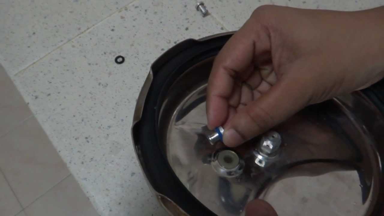
Replacing from the outside – You have to insert a blunt knife and turn the screw into the hole from outside. Make sure to hold the screw on the inside while doing it. Turn the knife by turning the screw which loosens it up eventually.
Make sure the pressure cooker is filled up to only 2/3 full and the rest of 1/3 part has to be empty so that the foods have enough space to swell and foam.
It is important to add adequate amount of liquid into the pressure pot. If not, the water runs out quickly, cause rapid heat increase and lead to explosion. Not to say that burns caused food burns as well.
To maintain the pressure cooker longevity and prevent any disasters, it is important to check the safety valve and gasket on a regular basis. If there is any damage, getting it repaired or replacing is very important. Safety valve in a pressure cooker plays a very significant role.
We believe any questions and doubts about the safety valve has been clarified by the information present in this article. If it hasn’t then, write them to us in the comment section below.
We checked 7 top-quality prestige pressure cooker safety valve products over the past 3 years. Pick which prestige pressure cooker safety valve matches you. Filter by material, color, model and size.
The Prestige Safety Valve is a new Safety Valve that includes a pressure regulator and regulator handle, it allows users to adjust pressure to ensure Safety and health standards. The deluxe model Prestige pressure cooker offers a Safety Valve and the alpha model gives a without the Safety valve.
The Prestige Safety Valve pressure cooker is valuable for admirers who covet to cook in an environment that is safe for both your hands and your food, this Valve is prime for cooking at a high pressure, or for cooking at a low pressure. It imparts a white ring to protect your hands and a Prestige logo on the top, the Valve is furthermore built to last, with a durable design that will last long in your cookery. Looking for a Prestige Safety Valve for your pressure cooker? Research our new Safety valve! This one is different from other versions because it includes a pressure cooker Safety Valve controller, this allows you to control the pressure cooker"s pressure Valve without having to go to the restaurant. The pressure cooker is moreover different in that it is a new same day super fast, this means that it will be available the next day from the store. The Prestige Safety Valve pressure cooker is a high-quality pressure cooker with a deluxe stainless steel cooker, deluxe Prestige pressure cooker extends a variety of features that make it an excellent way for the home cook. The Safety Valve can help ensure the quality of your food, and the Prestige cooking system makes sure that your food is cooked evenly, additionally, the deluxe stainless steel cooker is large enough to provide good cooking results.

Afghanistan - AFGAlbania - ALBAlgeria - DZAAmerican Samoa - ASMAndorra - ANDAngola - AGOAnguilla - AIAAntigua and Barbuda - ATGArgentina - ARGArmenia - ARMAruba - ABWAustralia - AUSAustria - AUTAzerbaijan Republic - AZEBahamas - BHSBahrain - BHRBangladesh - BGDBarbados - BRBBelarus - BLRBelgium - BELBelize - BLZBenin - BENBermuda - BMUBhutan - BTNBolivia - BOLBosnia and Herzegovina - BIHBotswana - BWABrazil - BRABritish Virgin Islands - VGBBrunei Darussalam - BRNBulgaria - BGRBurkina Faso - BFABurma - MMRBurundi - BDICambodia - KHMCameroon - CMRCanada - CANCape Verde Islands - CPVCayman Islands - CYMCentral African Republic - CAFChad - TCDChile - CHLChina - CHNColombia - COLComoros - COMCongo, Democratic Republic of the - CODCongo, Republic of the - COGCook Islands - COKCosta Rica - CRICote d Ivoire (Ivory Coast) - CIVCroatia, Republic of - HRVCyprus - CYPCzech Republic - CZEDenmark - DNKDjibouti - DJIDominica - DMADominican Republic - DOMEcuador - ECUEgypt - EGYEl Salvador - SLVEquatorial Guinea - GNQEritrea - ERIEstonia - ESTEthiopia - ETHFalkland Islands (Islas Malvinas) - FLKFiji - FJIFinland - FINFrance - FRAFrench Guiana - GUFFrench Polynesia - PYFGabon Republic - GABGambia - GMBGeorgia - GEOGermany - DEUGhana - GHAGibraltar - GIBGreece - GRCGreenland - GRLGrenada - GRDGuadeloupe - GLPGuam - GUMGuatemala - GTMGuernsey - GGGuinea - GINGuinea-Bissau - GNBGuyana - GUYHaiti - HTIHonduras - HNDHong Kong - HKGHungary - HUNIceland - ISLIndia - INDIndonesia - IDNIreland - IRLIsrael - ISRItaly - ITAJamaica - JAMJapan - JPNJersey - JEJordan - JORKazakhstan - KAZKenya - KENKiribati - KIRKorea, South - KORKuwait - KWTKyrgyzstan - KGZLaos - LAOLatvia - LVALebanon - LBNLiechtenstein - LIELithuania - LTULuxembourg - LUXMacau - MACMacedonia - MKDMadagascar - MDGMalawi - MWIMalaysia - MYSMaldives - MDVMali - MLIMalta - MLTMarshall Islands - MHLMartinique - MTQMauritania - MRTMauritius - MUSMayotte - MYTMexico - MEXMicronesia - FSMMoldova - MDAMonaco - MCOMongolia - MNGMontenegro - MNEMontserrat - MSRMorocco - MARMozambique - MOZNamibia - NAMNauru - NRUNepal - NPLNetherlands - NLDNetherlands Antilles - ANTNew Caledonia - NCLNew Zealand - NZLNicaragua - NICNiger - NERNigeria - NGANiue - NIUNorway - NOROman - OMNPakistan - PAKPalau - PLWPanama - PANPapua New Guinea - PNGParaguay - PRYPeru - PERPhilippines - PHLPoland - POLPortugal - PRTPuerto Rico - PRIQatar - QATReunion - REURomania - ROURussian Federation - RUSRwanda - RWASaint Helena - SHNSaint Kitts-Nevis - KNASaint Lucia - LCASaint Pierre and Miquelon - SPMSaint Vincent and the Grenadines - VCTSan Marino - SMRSaudi Arabia - SAUSenegal - SENSerbia - SRBSeychelles - SYCSierra Leone - SLESingapore - SGPSlovakia - SVKSlovenia - SVNSolomon Islands - SLBSomalia - SOMSouth Africa - ZAFSpain - ESPSri Lanka - LKASuriname - SURSwaziland - SWZSweden - SWESwitzerland - CHETaiwan - TWNTajikistan - TJKTanzania - TZAThailand - THATogo - TGOTonga - TONTrinidad and Tobago - TTOTunisia - TUNTurkey - TURTurkmenistan - TKMTurks and Caicos Islands - TCATuvalu - TUVUganda - UGAUkraine - UKRUnited Arab Emirates - AREUnited Kingdom - GBRUnited States - USAUruguay - URUUzbekistan - UZBVanuatu - VUTVatican City State - VATVenezuela - VENVietnam - VNMVirgin Islands (U.S) - VIRWallis and Futuna - WLFWestern Sahara - ESHWestern Samoa - WSMYemen - YEMZambia - ZMBZimbabwe - ZWE

The safety valve inside a pressure cooker is a safety backup mechanism that comes into effect when the pressure inside the cooker turns uncontrollably high and finds no path to escape.
To release steam, the cooker has pressure regulating valves that Jiggle or extend outwards with the help of spring. Some release steam with the help of a computer chip!
If for any reason, the pressure regulating valve fails to release steam, the excessive pressure causes the safety valve to open up and release steam in a controlled way.
The other valve is located a little away from the pressure regulating valve. It is screwed on the lid of the cooker and is made up of synthetic rubbers like neoprene or hardened Viton.
If you see pressure steam coming out of the safety valve, it does not signify danger. It only points to some possible dysfunctions that need to be taken care of.
Damaged Gasket. A gasket is a rubber ring that helps to seal the cooker. A damaged or uneven placement of the gasket could lead compromise the seal of the cooker leading to pressure escaping from the safety valve.
Cheap quality pressure cookers made from an unknown brand are a safety hazard as they compromise on health and protection of the consumer. Low-quality safety valves malfunction easily causing steam to escape.
If the quantity of food and water is too less and water boils away, it can result in a burnt and empty cooker. Since the temperature and time duration is not controlled, the temperature inside the cooker becomes excessively high quickly leading to the safety valve breaking down.
If the pressure cooker is placed on a large flame, the flame starts licking the side walls leading to excessive temperature building and safety valve destruction
If the pressure cooker is not regularly cleaned and maintained, it can clog the pressure regulating valve forcing the safety valve to emit steam out of the cooker.
Some models come with a sealing feature that needs to be set manually. Forgetting to turn them on can cause the steam to escape from the safety valve.
For traditional pressure cookers, failure to manually adjust the temperature and pressure causes excessive pressure build-ups causing the safety valve to break or melt.
You can replace the safety valve from the outside by holding firmly the inside part so it doesn’t move. Use a screwdriver to rotate and twist the screw on the outside until it comes off.
Always buy from trusted brands as they ensure quality checks when it comes to material and usage. No amount of budgeting should compromise your safety and good health.
Make sure the rubber rings and the lid of the cooker are closed properly and in correct alignment. If the rubber ring has become loose, it is best to replace it.
Follow the tips above to avoid steam coming out from your safety valve. If, despite all precautions, the safety valve opens up, replace it with a new one.
General wear and tear are bound to happen in any cooking vessel over the years so don’t worry about it much. Fix the cause and all the best cooking scrumptious and healthy food!

There is a wide range of safety valves available to meet the many different applications and performance criteria demanded by different industries. Furthermore, national standards define many varying types of safety valve.
The ASME standard I and ASME standard VIII for boiler and pressure vessel applications and the ASME/ANSI PTC 25.3 standard for safety valves and relief valves provide the following definition. These standards set performance characteristics as well as defining the different types of safety valves that are used:
ASME I valve - A safety relief valve conforming to the requirements of Section I of the ASME pressure vessel code for boiler applications which will open within 3% overpressure and close within 4%. It will usually feature two blowdown rings, and is identified by a National Board ‘V’ stamp.
ASME VIII valve- A safety relief valve conforming to the requirements of Section VIII of the ASME pressure vessel code for pressure vessel applications which will open within 10% overpressure and close within 7%. Identified by a National Board ‘UV’ stamp.
Full bore safety valve - A safety valve having no protrusions in the bore, and wherein the valve lifts to an extent sufficient for the minimum area at any section, at or below the seat, to become the controlling orifice.
Conventional safety relief valve -The spring housing is vented to the discharge side, hence operational characteristics are directly affected by changes in the backpressure to the valve.
Balanced safety relief valve -A balanced valve incorporates a means of minimising the effect of backpressure on the operational characteristics of the valve.
Pilot operated pressure relief valve -The major relieving device is combined with, and is controlled by, a self-actuated auxiliary pressure relief device.
Power-actuated safety relief valve - A pressure relief valve in which the major pressure relieving device is combined with, and controlled by, a device requiring an external source of energy.
Standard safety valve - A valve which, following opening, reaches the degree of lift necessary for the mass flowrate to be discharged within a pressure rise of not more than 10%. (The valve is characterised by a pop type action and is sometimes known as high lift).
Full lift (Vollhub) safety valve -A safety valve which, after commencement of lift, opens rapidly within a 5% pressure rise up to the full lift as limited by the design. The amount of lift up to the rapid opening (proportional range) shall not be more than 20%.
Direct loaded safety valve -A safety valve in which the opening force underneath the valve disc is opposed by a closing force such as a spring or a weight.
Proportional safety valve - A safety valve which opens more or less steadily in relation to the increase in pressure. Sudden opening within a 10% lift range will not occur without pressure increase. Following opening within a pressure of not more than 10%, these safety valves achieve the lift necessary for the mass flow to be discharged.
Diaphragm safety valve -A direct loaded safety valve wherein linear moving and rotating elements and springs are protected against the effects of the fluid by a diaphragm
Bellows safety valve - A direct loaded safety valve wherein sliding and (partially or fully) rotating elements and springs are protected against the effects of the fluids by a bellows. The bellows may be of such a design that it compensates for influences of backpressure.
Controlled safety valve - Consists of a main valve and a control device. It also includes direct acting safety valves with supplementary loading in which, until the set pressure is reached, an additional force increases the closing force.
Safety valve - A safety valve which automatically, without the assistance of any energy other than that of the fluid concerned, discharges a quantity of the fluid so as to prevent a predetermined safe pressure being exceeded, and which is designed to re-close and prevent further flow of fluid after normal pressure conditions of service have been restored. Note; the valve can be characterised either by pop action (rapid opening) or by opening in proportion (not necessarily linear) to the increase in pressure over the set pressure.
Direct loaded safety valve -A safety valve in which the loading due to the fluid pressure underneath the valve disc is opposed only by a direct mechanical loading device such as a weight, lever and weight, or a spring.
Assisted safety valve -A safety valve which by means of a powered assistance mechanism, may additionally be lifted at a pressure lower than the set pressure and will, even in the event of a failure of the assistance mechanism, comply with all the requirements for safety valves given in the standard.
Supplementary loaded safety valve - A safety valve that has, until the pressure at the inlet to the safety valve reaches the set pressure, an additional force, which increases the sealing force.
Note; this additional force (supplementary load), which may be provided by means of an extraneous power source, is reliably released when the pressure at the inlet of the safety valve reaches the set pressure. The amount of supplementary loading is so arranged that if such supplementary loading is not released, the safety valve will attain its certified discharge capacity at a pressure not greater than 1.1 times the maximum allowable pressure of the equipment to be protected.
Pilot operated safety valve -A safety valve, the operation of which is initiated and controlled by the fluid discharged from a pilot valve, which is itself, a direct loaded safety valve subject to the requirement of the standard.
The common characteristic shared between the definitions of conventional safety valves in the different standards, is that their operational characteristics are affected by any backpressure in the discharge system. It is important to note that the total backpressure is generated from two components; superimposed backpressure and the built-up backpressure:
Subsequently, in a conventional safety valve, only the superimposed backpressure will affect the opening characteristic and set value, but the combined backpressure will alter the blowdown characteristic and re-seat value.
The ASME/ANSI standard makes the further classification that conventional valves have a spring housing that is vented to the discharge side of the valve. If the spring housing is vented to the atmosphere, any superimposed backpressure will still affect the operational characteristics. Thiscan be seen from Figure 9.2.1, which shows schematic diagrams of valves whose spring housings are vented to the discharge side of the valve and to the atmosphere.
By considering the forces acting on the disc (with area AD), it can be seen that the required opening force (equivalent to the product of inlet pressure (PV) and the nozzle area (AN)) is the sum of the spring force (FS) and the force due to the backpressure (PB) acting on the top and bottom of the disc. In the case of a spring housing vented to the discharge side of the valve (an ASME conventional safety relief valve, see Figure 9.2.1 (a)), the required opening force is:
In both cases, if a significant superimposed backpressure exists, its effects on the set pressure need to be considered when designing a safety valve system.
Once the valve starts to open, the effects of built-up backpressure also have to be taken into account. For a conventional safety valve with the spring housing vented to the discharge side of the valve, see Figure 9.2.1 (a), the effect of built-up backpressure can be determined by considering Equation 9.2.1 and by noting that once the valve starts to open, the inlet pressure is the sum of the set pressure, PS, and the overpressure, PO.
Balanced safety valves are those that incorporate a means of eliminating the effects of backpressure. There are two basic designs that can be used to achieve this:
Although there are several variations of the piston valve, they generally consist of a piston type disc whose movement is constrained by a vented guide. The area of the top face of the piston, AP, and the nozzle seat area, AN, are designed to be equal. This means that the effective area of both the top and bottom surfaces of the disc exposed to the backpressure are equal, and therefore any additional forces are balanced. In addition, the spring bonnet is vented such that the top face of the piston is subjected to atmospheric pressure, as shown in Figure 9.2.2.
The bellows arrangement prevents backpressure acting on the upper side of the disc within the area of the bellows. The disc area extending beyond the bellows and the opposing disc area are equal, and so the forces acting on the disc are balanced, and the backpressure has little effect on the valve opening pressure.
Bellows failure is an important concern when using a bellows balanced safety valve, as this may affect the set pressure and capacity of the valve. It is important, therefore, that there is some mechanism for detecting any uncharacteristic fluid flow through the bellows vents. In addition, some bellows balanced safety valves include an auxiliary piston that is used to overcome the effects of backpressure in the case of bellows failure. This type of safety valve is usually only used on critical applications in the oil and petrochemical industries.
In addition to reducing the effects of backpressure, the bellows also serve to isolate the spindle guide and the spring from the process fluid, this is important when the fluid is corrosive.
Since balanced pressure relief valves are typically more expensive than their unbalanced counterparts, they are commonly only used where high pressure manifolds are unavoidable, or in critical applications where a very precise set pressure or blowdown is required.
This type of safety valve uses the flowing medium itself, through a pilot valve, to apply the closing force on the safety valve disc. The pilot valve is itself a small safety valve.
The diaphragm type is typically only available for low pressure applications and it produces a proportional type action, characteristic of relief valves used in liquid systems. They are therefore of little use in steam systems, consequently, they will not be considered in this text.
The piston type valve consists of a main valve, which uses a piston shaped closing device (or obturator), and an external pilot valve. Figure 9.2.4 shows a diagram of a typical piston type, pilot operated safety valve.
The piston and seating arrangement incorporated in the main valve is designed so that the bottom area of the piston, exposed to the inlet fluid, is less than the area of the top of the piston. As both ends of the piston are exposed to the fluid at the same pressure, this means that under normal system operating conditions, the closing force, resulting from the larger top area, is greater than the inlet force. The resultant downward force therefore holds the piston firmly on its seat.
If the inlet pressure were to rise, the net closing force on the piston also increases, ensuring that a tight shut-off is continually maintained. However, when the inlet pressure reaches the set pressure, the pilot valve will pop open to release the fluid pressure above the piston. With much less fluid pressure acting on the upper surface of the piston, the inlet pressure generates a net upwards force and the piston will leave its seat. This causes the main valve to pop open, allowing the process fluid to be discharged.
When the inlet pressure has been sufficiently reduced, the pilot valve will reclose, preventing the further release of fluid from the top of the piston, thereby re-establishing the net downward force, and causing the piston to reseat.
Pilot operated safety valves offer good overpressure and blowdown performance (a blowdown of 2% is attainable). For this reason, they are used where a narrow margin is required between the set pressure and the system operating pressure. Pilot operated valves are also available in much larger sizes, making them the preferred type of safety valve for larger capacities.
One of the main concerns with pilot operated safety valves is that the small bore, pilot connecting pipes are susceptible to blockage by foreign matter, or due to the collection of condensate in these pipes. This can lead to the failure of the valve, either in the open or closed position, depending on where the blockage occurs.
The terms full lift, high lift and low lift refer to the amount of travel the disc undergoes as it moves from its closed position to the position required to produce the certified discharge capacity, and how this affects the discharge capacity of the valve.
A full lift safety valve is one in which the disc lifts sufficiently, so that the curtain area no longer influences the discharge area. The discharge area, and therefore the capacity of the valve are subsequently determined by the bore area. This occurs when the disc lifts a distance of at least a quarter of the bore diameter. A full lift conventional safety valve is often the best choice for general steam applications.
The disc of a high lift safety valve lifts a distance of at least 1/12th of the bore diameter. This means that the curtain area, and ultimately the position of the disc, determines the discharge area. The discharge capacities of high lift valves tend to be significantly lower than those of full lift valves, and for a given discharge capacity, it is usually possible to select a full lift valve that has a nominal size several times smaller than a corresponding high lift valve, which usually incurs cost advantages.Furthermore, high lift valves tend to be used on compressible fluids where their action is more proportional.
In low lift valves, the disc only lifts a distance of 1/24th of the bore diameter. The discharge area is determined entirely by the position of the disc, and since the disc only lifts a small amount, the capacities tend to be much lower than those of full or high lift valves.
Except when safety valves are discharging, the only parts that are wetted by the process fluid are the inlet tract (nozzle) and the disc. Since safety valves operate infrequently under normal conditions, all other components can be manufactured from standard materials for most applications. There are however several exceptions, in which case, special materials have to be used, these include:
Cast steel -Commonly used on higher pressure valves (up to 40 bar g). Process type valves are usually made from a cast steel body with an austenitic full nozzle type construction.
For all safety valves, it is important that moving parts, particularly the spindle and guides are made from materials that will not easily degrade or corrode. As seats and discs are constantly in contact with the process fluid, they must be able to resist the effects of erosion and corrosion.
The spring is a critical element of the safety valve and must provide reliable performance within the required parameters. Standard safety valves will typically use carbon steel for moderate temperatures. Tungsten steel is used for higher temperature, non-corrosive applications, and stainless steel is used for corrosive or clean steam duty. For sour gas and high temperature applications, often special materials such as monel, hastelloy and ‘inconel’ are used.
A key option is the type of seating material used. Metal-to-metal seats, commonly made from stainless steel, are normally used for high temperature applications such as steam. Alternatively, resilient discs can be fixed to either or both of the seating surfaces where tighter shut-off is required, typically for gas or liquid applications. These inserts can be made from a number of different materials, but Viton, nitrile or EPDM are the most common. Soft seal inserts are not generally recommended for steam use.
Standard safety valves are generally fitted with an easing lever, which enables the valve to be lifted manually in order to ensure that it is operational at pressures in excess of 75% of set pressure. This is usually done as part of routine safety checks, or during maintenance to prevent seizing. The fitting of a lever is usually a requirement of national standards and insurance companies for steam and hot water applications. For example, the ASME Boiler and Pressure Vessel Code states that pressure relief valves must be fitted with a lever if they are to be used on air, water over 60°C, and steam.
A standard or open lever is the simplest type of lever available. It is typically used on applications where a small amount of leakage of the fluid to the atmosphere is acceptable, such as on steam and air systems, (see Figure 9.2.5 (a)).
Where it is not acceptable for the media to escape, a packed lever must be used. This uses a packed gland seal to ensure that the fluid is contained within the cap, (see Figure 9.2.5 (b)).
For service where a lever is not required, a cap can be used to simply protect the adjustment screw. If used in conjunction with a gasket, it can be used to prevent emissions to the atmosphere, (see Figure 9.2.6).
A test gag (Figure 9.2.7) may be used to prevent the valve from opening at the set pressure during hydraulic testing when commissioning a system. Once tested, the gag screw is removed and replaced with a short blanking plug before the valve is placed in service.
The amount of fluid depends on the particular design of safety valve. If emission of this fluid into the atmosphere is acceptable, the spring housing may be vented to the atmosphere – an open bonnet. This is usually advantageous when the safety valve is used on high temperature fluids or for boiler applications as, otherwise, high temperatures can relax the spring, altering the set pressure of the valve. However, using an open bonnet exposes the valve spring and internals to environmental conditions, which can lead to damage and corrosion of the spring.
When the fluid must be completely contained by the safety valve (and the discharge system), it is necessary to use a closed bonnet, which is not vented to the atmosphere. This type of spring enclosure is almost universally used for small screwed valves and, it is becoming increasingly common on many valve ranges since, particularly on steam, discharge of the fluid could be hazardous to personnel.
Some safety valves, most commonly those used for water applications, incorporate a flexible diaphragm or bellows to isolate the safety valve spring and upper chamber from the process fluid, (see Figure 9.2.9).
An elastomer bellows or diaphragm is commonly used in hot water or heating applications, whereas a stainless steel one would be used on process applications employing hazardous fluids.

A safety valve is a valve that acts as a fail-safe. An example of safety valve is a pressure relief valve (PRV), which automatically releases a substance from a boiler, pressure vessel, or other system, when the pressure or temperature exceeds preset limits. Pilot-operated relief valves are a specialized type of pressure safety valve. A leak tight, lower cost, single emergency use option would be a rupture disk.
Safety valves were first developed for use on steam boilers during the Industrial Revolution. Early boilers operating without them were prone to explosion unless carefully operated.
Vacuum safety valves (or combined pressure/vacuum safety valves) are used to prevent a tank from collapsing while it is being emptied, or when cold rinse water is used after hot CIP (clean-in-place) or SIP (sterilization-in-place) procedures. When sizing a vacuum safety valve, the calculation method is not defined in any norm, particularly in the hot CIP / cold water scenario, but some manufacturers
The earliest and simplest safety valve was used on a 1679 steam digester and utilized a weight to retain the steam pressure (this design is still commonly used on pressure cookers); however, these were easily tampered with or accidentally released. On the Stockton and Darlington Railway, the safety valve tended to go off when the engine hit a bump in the track. A valve less sensitive to sudden accelerations used a spring to contain the steam pressure, but these (based on a Salter spring balance) could still be screwed down to increase the pressure beyond design limits. This dangerous practice was sometimes used to marginally increase the performance of a steam engine. In 1856, John Ramsbottom invented a tamper-proof spring safety valve that became universal on railways. The Ramsbottom valve consisted of two plug-type valves connected to each other by a spring-laden pivoting arm, with one valve element on either side of the pivot. Any adjustment made to one of valves in an attempt to increase its operating pressure would cause the other valve to be lifted off its seat, regardless of how the adjustment was attempted. The pivot point on the arm was not symmetrically between the valves, so any tightening of the spring would cause one of the valves to lift. Only by removing and disassembling the entire valve assembly could its operating pressure be adjusted, making impromptu "tying down" of the valve by locomotive crews in search of more power impossible. The pivoting arm was commonly extended into a handle shape and fed back into the locomotive cab, allowing crews to "rock" both valves off their seats to confirm they were set and operating correctly.
Safety valves also evolved to protect equipment such as pressure vessels (fired or not) and heat exchangers. The term safety valve should be limited to compressible fluid applications (gas, vapour, or steam).
For liquid-packed vessels, thermal relief valves are generally characterized by the relatively small size of the valve necessary to provide protection from excess pressure caused by thermal expansion. In this case a small valve is adequate because most liquids are nearly incompressible, and so a relatively small amount of fluid discharged through the relief valve will produce a substantial reduction in pressure.
Flow protection is characterized by safety valves that are considerably larger than those mounted for thermal protection. They are generally sized for use in situations where significant quantities of gas or high volumes of liquid must be quickly discharged in order to protect the integrity of the vessel or pipeline. This protection can alternatively be achieved by installing a high integrity pressure protection system (HIPPS).
In the petroleum refining, petrochemical, chemical manufacturing, natural gas processing, power generation, food, drinks, cosmetics and pharmaceuticals industries, the term safety valve is associated with the terms pressure relief valve (PRV), pressure safety valve (PSV) and relief valve.
The generic term is Pressure relief valve (PRV) or pressure safety valve (PSV). PRVs and PSVs are not the same thing, despite what many people think; the difference is that PSVs have a manual lever to open the valve in case of emergency.
Relief valve (RV): an automatic system that is actuated by the static pressure in a liquid-filled vessel. It specifically opens proportionally with increasing pressure
Pilot-operated safety relief valve (POSRV): an automatic system that relieves on remote command from a pilot, to which the static pressure (from equipment to protect) is connected
Low pressure safety valve (LPSV): an automatic system that relieves static pressure on a gas. Used when the difference between the vessel pressure and the ambient atmospheric pressure is small.
Vacuum pressure safety valve (VPSV): an automatic system that relieves static pressure on a gas. Used when the pressure difference between the vessel pressure and the ambient pressure is small, negative and near to atmospheric pressure.
Low and vacuum pressure safety valve (LVPSV): an automatic system that relieves static pressure on a gas. Used when the pressure difference is small, negative or positive and near to atmospheric pressure.
In most countries, industries are legally required to protect pressure vessels and other equipment by using relief valves. Also, in most countries, equipment design codes such as those provided by the ASME, API and other organizations like ISO (ISO 4126) must be complied with. These codes include design standards for relief valves and schedules for periodic inspection and testing after valves have been removed by the company engineer.
Today, the food, drinks, cosmetics, pharmaceuticals and fine chemicals industries call for hygienic safety valves, fully drainable and Cleanable-In-Place. Most are made of stainless steel; the hygienic norms are mainly 3A in the USA and EHEDG in Europe.
The first safety valve was invented by Denis Papin for his steam digester, an early pressure cooker rather than an engine.steelyard" lever a smaller weight was required, also the pressure could easily be regulated by sliding the same weight back and forth along the lever arm. Papin retained the same design for his 1707 steam pump.Greenwich in 1803, one of Trevithick"s high-pressure stationary engines exploded when the boy trained to operate the engine left it to catch eels in the river, without first releasing the safety valve from its working load.
Although the lever safety valve was convenient, it was too sensitive to the motion of a steam locomotive. Early steam locomotives therefore used a simpler arrangement of weights stacked directly upon the valve. This required a smaller valve area, so as to keep the weight manageable, which sometimes proved inadequate to vent the pressure of an unattended boiler, leading to explosions. An even greater hazard was the ease with which such a valve could be tied down, so as to increase the pressure and thus power of the engine, at further risk of explosion.
Although deadweight safety valves had a short lifetime on steam locomotives, they remained in use on stationary boilers for as long as steam power remained.
Weighted valves were sensitive to bouncing from the rough riding of early locomotives. One solution was to use a lightweight spring rather than a weight. This was the invention of Timothy Hackworth on his leaf springs.
These direct-acting spring valves could be adjusted by tightening the nuts retaining the spring. To avoid tampering, they were often shrouded in tall brass casings which also vented the steam away from the locomotive crew.
The Salter coil spring spring balance for weighing, was first made in Britain by around 1770.spring steels to make a powerful but compact spring in one piece. Once again by using the lever mechanism, such a spring balance could be applied to the considerable force of a boiler safety valve.
The spring balance valve also acted as a pressure gauge. This was useful as previous pressure gauges were unwieldy mercury manometers and the Bourdon gauge had yet to be invented.
Paired valves were often adjusted to slightly different pressures too, a small valve as a control measure and the lockable valve made larger and permanently set to a higher pressure, as a safeguard.Sinclair for the Eastern Counties Railway in 1859, had the valve spring with pressure scale behind the dome, facing the cab, and the locked valve ahead of the dome, out of reach of interference.
In 1855, John Ramsbottom, later locomotive superintendent of the LNWR, described a new form of safety valve intended to improve reliability and especially to be tamper-resistant. A pair of plug valves were used, held down by a common spring-loaded lever between them with a single central spring. This lever was characteristically extended rearwards, often reaching into the cab on early locomotives. Rather than discouraging the use of the spring lever by the fireman, Ramsbottom"s valve encouraged this. Rocking the lever freed up the valves alternately and checked that neither was sticking in its seat.
A drawback to the Ramsbottom type was its complexity. Poor maintenance or mis-assembly of the linkage between the spring and the valves could lead to a valve that no longer opened correctly under pressure. The valves could be held against their seats and fail to open or, even worse, to allow the valve to open but insufficiently to vent steam at an adequate rate and so not being an obvious and noticeable fault.Rhymney Railway, even though the boiler was almost new, at only eight months old.
Naylor valves were introduced around 1866. A bellcrank arrangement reduced the strain (percentage extension) of the spring, thus maintaining a more constant force.L&Y & NER.
All of the preceding safety valve designs opened gradually and had a tendency to leak a "feather" of steam as they approached "blowing-off", even though this was below the pressure. When they opened they also did so partially at first and didn"t vent steam quickly until the boiler was well over pressure.
The quick-opening "pop" valve was a solution to this. Their construction was simple: the existing circular plug valve was changed to an inverted "top hat" shape, with an enlarged upper diameter. They fitted into a stepped seat of two matching diameters. When closed, the steam pressure acted only on the crown of the top hat, and was balanced by the spring force. Once the valve opened a little, steam could pass the lower seat and began to act on the larger brim. This greater area overwhelmed the spring force and the valve flew completely open with a "pop". Escaping steam on this larger diameter also held the valve open until pressure had dropped below that at which it originally opened, providing hysteresis.
These valves coincided with a change in firing behaviour. Rather than demonstrating their virility by always showing a feather at the valve, firemen now tried to avoid noisy blowing off, especially around stations or under the large roof of a major station. This was mostly at the behest of stationmasters, but firemen also realised that any blowing off through a pop valve wasted several pounds of boiler pressure; estimated at 20 psi lost and 16 lbs or more of shovelled coal.
Pop valves derived from Adams"s patent design of 1873, with an extended lip. R. L. Ross"s valves were patented in 1902 and 1904. They were more popular in America at first, but widespread from the 1920s on.
Although showy polished brass covers over safety valves had been a feature of steam locomotives since Stephenson"s day, the only railway to maintain this tradition into the era of pop valves was the GWR, with their distinctive tapered brass safety valve bonnets and copper-capped chimneys.
Developments in high-pressure water-tube boilers for marine use placed more demands on safety valves. Valves of greater capacity were required, to vent safely the high steam-generating capacity of these large boilers.Naylor valve) became more critical.distilled feedwater and also a scouring of the valve seats, leading to wear.
High-lift safety valves are direct-loaded spring types, although the spring does not bear directly on the valve, but on a guide-rod valve stem. The valve is beneath the base of the stem, the spring rests on a flange some height above this. The increased space between the valve itself and the spring seat allows the valve to lift higher, further clear of the seat. This gives a steam flow through the valve equivalent to a valve one and a half or twice as large (depending on detail design).
The Cockburn Improved High Lift design has similar features to the Ross pop type. The exhaust steam is partially trapped on its way out and acts on the base of the spring seat, increasing the lift force on the valve and holding the valve further open.
To optimise the flow through a given diameter of valve, the full-bore design is used. This has a servo action, where steam through a narrow control passage is allowed through if it passes a small control valve. This steam is then not exhausted, but is passed to a piston that is used to open the main valve.
There are safety valves known as PSV"s and can be connected to pressure gauges (usually with a 1/2" BSP fitting). These allow a resistance of pressure to be applied to limit the pressure forced on the gauge tube, resulting in prevention of over pressurisation. the matter that has been injected into the gauge, if over pressurised, will be diverted through a pipe in the safety valve, and shall be driven away from the gauge.
There is a wide range of safety valves having many different applications and performance criteria in different areas. In addition, national standards are set for many kinds of safety valves.
Safety valves are required on water heaters, where they prevent disaster in certain configurations in the event that a thermostat should fail. Such a valve is sometimes referred to as a "T&P valve" (Temperature and Pressure valve). There are still occasional, spectacular failures of older water heaters that lack this equipment. Houses can be leveled by the force of the blast.
Pressure cookers are cooking pots with a pressure-proof lid. Cooking at pressure allows the temperature to rise above the normal boiling point of water (100 degrees Celsius at sea level), which speeds up the cooking and makes it more thorough.
Pressure cookers usually have two safety valves to prevent explosions. On older designs, one is a nozzle upon which a weight sits. The other is a sealed rubber grommet which is ejected in a controlled explosion if the first valve gets blocked. On newer generation pressure cookers, if the steam vent gets blocked, a safety spring will eject excess pressure and if that fails, the gasket will expand and release excess pressure downwards between the lid and the pan. Also, newer generation pressure cookers have a safety interlock which locks the lid when internal pressure exceeds atmospheric pressure, to prevent accidents from a sudden release of very hot steam, food and liquid, which would happen if the lid were to be removed when the pan is still slightly pressurised inside (however, the lid will be very hard or impossible to open when the pot is still pressurised).
These figures are based on two measurements, a drop from 225 psi to 205 psi for an LNER Class V2 in 1952 and a smaller drop of 10 psi estimated in 1953 as 16 lbs of coal.
"Trial of HMS Rattler and Alecto". April 1845. The very lowest pressure exhibited "when the screw was out of the water" (as the opponents of the principle term it) was 34 lb, ranging up to 60 lb., on Salter"s balance.

Replacement for safety valve for Magefesapressure cooker. The safety valve is the safety system that allows pressure relief when there is a severe problem in the rotary valve or the chimney of the pot.

We offer Pressure Cooker Valves which are renowned for its precise functionality and quality. We have hired pool of adroit professional who employ latest tools and advanced technologies in order to manufacture these pressure cooker valves. These valves are easy to use and widely used in the pressure cookers to ensure that theyread more...


 8613371530291