
how to test a gas oven safety valve free sample

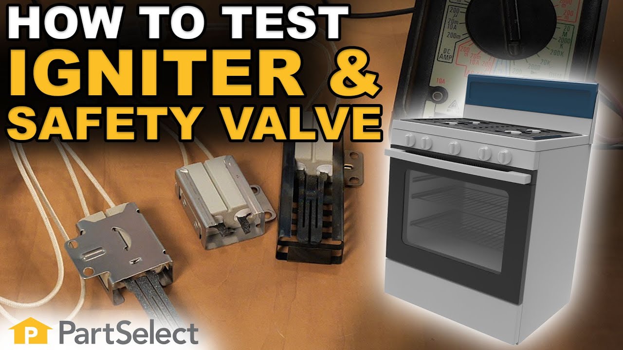
Trouble turning on your gas stove? If your igniter is glowing but there is no flame, then one of two components in your range are at fault. These components are the “safety valve” and the igniter itself.
Take a clamp-on type ammeter, and attach it to the circuit to determine whether the igniter is working efficiently enough to open the safety valve. Clamp your meter onto the wire that either goes to the bake burner igniter or the bake burner safety valve. Turn on the bake function, and see what current is drawn. Typically your meter will show 2.8 – 3.0 amps for a normal current draw for a working igniter. If your meter is showing 2.7 or lower then you can assume that the igniter is not drawing enough current to actually ignite the flame, and therefore it won’t open the oven safety valve to allow the gas to enter the burner chamber. If this happens, it’s time to replace the oven burner igniter.
For a “hot surface” or “glow bar igniter” you can test their power continuity using a multimeter. Simply insert both leads onto the terminals for the igniter and measure the resistance. If it shows resistance, it has continuity. No resistance? No continuity. Typically these will be somewhere between 80 and 175 ohms of resistance for a working igniter.
To test the oven safety valve, measure between the two terminals, on the valve and look for continuity. The resistance here is low, but you should be able to detect 1 to 1.5 ohms. If your model uses a dual valve, one for the broil burner and one for the bake burner, then you will have two bi-metals and again you can test them for continuity using a multimeter. They also should be very low resistance and those would indicate that they"re normal working oven safety valves.
If after performing these tests, you"ve determined that you need to replace your gas range"s oven safety valves, oven igniter, burn igniter, or safety valves? Take a look at our large selection of oven parts.

Pilot ignition systems use a flame sensing element to sense whether the pilot is lit and the safety valve can open. The sensing element sits right in the pilot flame.
Just exactly where the sensor sits in the pilot flame is important. (See figure 6-A) If the sensing bulb is not in the right part of the flame, or if the pilot is adjusted too low or too high, it will not get hot enough and the safety valve will not open.
When two dissimilar metals (for example, copper and steel) are bonded together electrically, and then heated, they generate a tiny electrical current between them. The voltage is very small, measured in millivolts. This is the basis for a millivolt oven ignitor system. All that"s needed is a safety valve that will sense this tiny voltage and open the valve if it is present. If the pilot is out, there is no millivoltage and the safety valve will not open. See figure 6-B.
If the burner in a millivolt system will not start, typically the problem is the gas valve. Occasionally the problem might be the pilot generator or thermostat. The thermostat in these is just a temperature-sensitive on/off switch. To test, turn it on and test for continuity.
If that doesn"t work, we have a minor dilemma in determining whether the problem is the pilot generator or the safety valve. The dilemma here is that the voltages are too small to be measured with standard equipment. VOM millivolt adaptors cost nearly as much as the pilot generator itself. And the safety valve, which is usually the problem, costs twice as much as the pilot generator. So usually you just replace either or both of them. But don"t forget they are electrical parts, which are non-returnable. What I recommend is just to replace the gas valve first; that usually will solve the problem. If not, replace the pilot generator. You just ate a gas valve, but trust me, you"d have bought one sooner or later anyway.
When installing the pilot generator, screw it into the safety valve finger tight, plus 1/4 turn. Any tighter than that and you can damage the electrical contacts on the valve.
In some systems the sensor is a liquid-filled bulb, with a capillary to the safety valve or flame switch. When the liquid inside heats up, it expands and exerts pressure on a diaphragm, which opens the valve or closes the switch.
It is important to know that these sensor bulbs do not cycle the burner on and off to maintain oven temperature. That is the thermostat"s function. It has a sensor bulb too, but it senses oven temperature, not pilot flame. The only function of these pilot sensing elements is to prevent gas flow to the burner if the bulb does not get hot enough to assure burner ignition.
In flame switch systems, hydraulic pressure from the capillary physically closes the switch, which completes an electrical circuit to the safety valve. The safety valve is electrical and operates on 110 volts. See Figure 6-D. If the pilot is out, the flame switch does not close and the 110 volt heating circuit is not complete, so the safety valve will not open.
Some of these direct-pressure (hydraulic) systems use a two-level pilot. The pilot stays at a very low level; not even high enough to activate the safety valve. This is called the constant pilot, or primary pilot. Gas for the primary pilot may come from either the thermostat or directly from the gas manifold.
When the thermostat valve is turned on, the pilot flame gets bigger, heating the sensor bulb, which activates the safety valve (hydraulically) and the burner ignites. This is called the heater pilot, or secondary pilot. Gas for the secondary pilot comes from the oven thermostat itself.
When the gas oven reaches the correct temperature setting, the thermostat drops the pilot flame back to the lower level, the safety valve closes and the burner shuts off. See figure 6-E.
The sensing bulb needs to be sitting right in the hottest part of the flame as described in section 6-2. If you don"t have a good strong pilot (secondary pilot, in two-level systems) that engulfs the pilot sensing bulb with flame, try cleaning the pilot assembly and sensor bulb as described in section 6-5. If that doesn"t work, replace the pilot assembly.
If you do have a good strong pilot that engulfs the pilot sensing bulb with flame, then odds are that the sensing element and/or whatever it is attached to are defective. If it is a flame switch, replace the flame switch. If it is a safety valve replace that.
In a two-level pilot system, remember that the main oven thermostat supplies the secondary pilot with gas. So if you cannot get a good secondary pilot the problem may be the pilot assembly, or it may be the thermostat. If you do get a good secondary pilot, you"re back to the sensing bulb and safety valve.
Spark ignition systems use a spark module to generate a pulsing, high-voltage spark to ignite the gas. The spark module is an electronic device that produces 2-4 high-voltage electrical pulses per second. These pulses are at very low amperage, measured in milliamps, so the risk of shock is virtually nil. But the voltage is high enough to jump an air gap and ignite gas. The spark ignition module is usually located either under the cooktop or inside the back of the stove. The same module is used for both the surface burner ignition and the oven burner ignition.
However, the spark is not certain enough to light the oven burner, and the gas flow is too high, to rely on the spark alone. Remember, in an oven, before the safety valve opens, you need to be assured of ignition. So the spark ignites a low-gasflow pilot, and then the safety valve opens only when the pilot is lit.
This is the same two-level pilot system described in section 6-2(b), with a few important exceptions. The constant or primary pilot does not stay lit when the oven thermostat is turned off. It does, however, stay lit the whole time the oven thermostat is turned on.
When the gas oven is turned on, a switch mounted to the oven thermostat stem signals the spark module. These are the same switches as shown in section 5-3.
The flame is positioned between the spark electrode and its target. The pilot flame actually conducts electricity. So when the pilot flame is burning, electricity from the spark electrode is drained off to ground, and sparking stops. If the pilot quits, sparking resumes.
When the thermostat calls for more heat in the oven, the heater or secondary pilot increases the size of the pilot flame, which heats the sensing bulb, which opens the safety valve and kicks on the burner.
Yup, this ol" boy"s got it all. Spark ignition, a pilot, a flame switch and TWO - count "em - TWO safety valves; one for the pilot and one for the burner. (Figure 6-H)
The operation is actually simpler than the diagram looks. When you turn on the oven thermostat, a cam on the thermostat hub closes the pilot valve switch. This opens the 110 volt pilot safety valve and energizes the spark module, igniting the pilot. As in the other spark system, the pilot flame provides a path that drains off the spark current, so the ignitor stops sparking while the pilot is lit. As long as the oven thermostat is turned on, the pilot valve switch stays closed, so the pilot valve stays open and the pilot stays lit.
When the pilot heats the pilot sensing element of the flame switch, the flame switch closes. This completes the 110 volt circuit to the oven safety valve, so the valve opens and the burner ignites.
When the oven temperature reaches the set point of the thermostat, the thermostat switch opens, breaking the circuit and closing the oven safety valve, and shutting off the burner.
Now that you know how the system works, first look to see what is not working. When the oven thermostat is on, and there isn"t a pilot flame, is the electrode sparking? Is there spark, but no primary pilot? Is the primary pilot igniting, but not the secondary? Is there sparking after the thermostat is shut off?
(The pilot may or may not light, but the main burner is not lighting) Remember that the thermostat supplies the pilot with gas in these ovens, and only when the thermostat is on. So if you don"t have a primary and secondary pilot flame, odds are the problem is the pilot orifice or oven thermostat. Try cleaning the pilot assembly and sensor bulb as described in section 6-5. If that doesn"t work, adjust the secondary flame a little higher. If that doesn"t work, replace the pilot assembly.
If you do have a good strong secondary pilot that engulfs the pilot sensing bulb with flame, then odds are that the oven safety valve (or flame switch, whichever is attached to the pilot sensing bulb in your system) is defective. Replace the defective component.
Something is wrong with the high-voltage sparking system. If you are in a hurry to use your oven, you can turn on the oven thermostat, carefully ignite the primary pilot with a match and use the oven for now; but remember that the minute you turn off the thermostat, the pilot goes out.
Are the cooktop ignitors sparking? If so, the spark module is probably OK. What typically goes wrong with the sparking system is that the rotary switch on the valve stops working. Test continuity as described in section 5-3(a). If that isn"t the problem, check the electrode for damage and proper adjustment. The spark target (the nearest metal to the electrode) should be about 1/8″ to 3/16″ away from it, (about the thickness of 2-3 dimes) and directly across the primary pilot orifice. Replace or adjust the electrode as appropriate. When replacing, make sure you get the right kind of electrode (there are several) and do not cut the electrode lead; follow it all the way back to the spark module and plug the new lead into the proper spark module terminal.
Usually the ignition switch has gotten some moisture in it and it is shorting. To test, pull the lead off the switch and see if the sparking stops. If so, the switch is bad. Replace it.
Remember that these switches are on 110 volt circuits. If you get too fast and loose with pulling these leads off to test them, you might zap yourself.

If your gas range is not working correctly, you should check the gas pressure regulator shut-off valve. The factory default setting for the gas pressure regulator is in the "ON" position but may have been turned to the "OFF" position during handling or transportation. When the shut-off valve is on the "OFF" position, gas will flow to the cooktop burners but will not provide a gas supply to the oven.
You can check if the shut-off valve if you can slide the range out from the cabinet. If you are unable to slide the range out, we recommend consultation with a local certified technician.
Verify the pressure regulator shut-off valve is in the open position. The pressure regulator is located at the back of the range. Make sure that the shut-off valve lever is in the "On" position (see illustration below).
NOTE: If the range is hard piped, you will not be able to slide it out from the cabinet if it connected with a flexible supply line, take care not to over-extend the supply line. The main gas valve will usually be at the end of a fixed pipe and connect to the pressure regulator with a flexible supply line. Take care not to kink or pinch this flexible pipe.
Most modern appliances have safety features built in, but your gas oven safety valve is arguably the most important. If an electrical appliance malfunctions, it can cause a fire, but a misfiring gas oven could potentially blow up your house. You don"t really need to know how the safety mechanism works to use your oven, but you may find that it gives you some extra peace of mind.
Broadly speaking, there are two ways a built-in safety mechanism can work. One option is that it remains "open" by default and to shut off if certain conditions are met. That"s how fuses and circuit breakers work in an electrical circuit: Ordinarily, the electricity is free to flow, but if the current grows too large, the fuse or breaker will blow and cut off the circulation of electricity.
The other option is for your safety mechanism to be "closed" by default and allow a device to operate only when the correct conditions are met. That"s how a gas oven safety valve works. Gas ordinarily is prevented from flowing, and if the valve is working correctly, it opens only when you want to light your oven.
Many gas stoves use what"s called a "hot surface igniter," a bar or element (similar to the ones on your stovetop) that gets hot enough to ignite the gas on contact. Gas oven safety valves on stoves with this type of ignition system take a couple of different approaches.
In one approach, a bimetallic strip operates the valve. It harnesses a simple scientific principle: Metals expand and contract at different rates when they"re heated and cooled. If you bond two suitable metals together in one strip, that strip will flex to a predictable degree as the temperature goes up and down. Wall-mount thermostats often use this principle, as do analog oven thermometers and the thermometer in the lid of your gas grill.
As appliance-repair website PartSelect explains, turning on your gas oven causes electricity to flow into the heating element of your hot surface igniter. As the igniter heats up, it warms a bimetallic strip inside your gas oven safety valve. When the igniter reaches its operating temperature, the bimetallic strip opens the valve and allows the gas to flow, igniting as it crosses the heated surface.
One intriguing thing about electricity is that a change in temperature can affect how well it passes through certain materials. For example, a lot of research revolves around superconductors – materials that offer very little resistance to an electrical current – but superconductors typically must be heavily chilled to work.
According to heating-equipment vendor Anglo Nordic, gas oven safety valves use a variation of that principle to operate. In these stoves, the flow of electrical current through the hot surface igniter becomes the control mechanism. The igniter"s bar is made of a material that offers less and less resistance to electricity as it heats. When it reaches the temperature required to ignite the gas, its resistance becomes low enough to trip the safety valve and open the flow of gas.
More modern ranges use an electrical igniter. When you turn on your oven, the gas begins flowing immediately, and it sends an electrical current to a piezo electric igniter. The current makes the igniter spark (like the manual igniter on your gas grill) and lights the oven"s burner. In this case, the safety valve works in the opposite way: An electronic sensor checks for the heat caused by ignition after a few seconds, and if it"s absent, it will close the valve and shut off the flow of gas.
It"s worth pointing out that not all gas ovens have a safety valve in the conventional sense. Older stoves simply use a pilot light, a small but constant flow of gas, which, in turn, feeds a small, candle-like flame. You essentially are the safety mechanism in this system: It"s up to you to check that the pilot is lit. When you turn on the gas manually, the small pilot flame ignites the main flame. It"s a mechanically simple system, which makes it durable, and for that reason, you"ll still see it used on commercial restaurant ranges, which must stand up to decades of heavy use.

Safety is of the utmost importance when dealing with pressure relief valves. The valve is designed to limit system pressure, and it is critical that they remain in working order to prevent an explosion. Explosions have caused far too much damage in companies over the years, and though pressurized tanks and vessels are equipped with pressure relief vales to enhance safety, they can fail and result in disaster.
That’s also why knowing the correct way to test the valves is important. Ongoing maintenance and periodic testing of pressurized tanks and vessels and their pressure relief valves keeps them in working order and keep employees and their work environments safe. Pressure relief valves must be in good condition in order to automatically lower tank and vessel pressure; working valves open slowly when the pressure gets high enough to exceed the pressure threshold and then closes slowly until the unit reaches the low, safe threshold. To ensure the pressure relief valve is in good working condition, employees must follow best practices for testing them including:
If you consider testing pressure relief valves a maintenance task, you’ll be more likely to carry out regular testing and ensure the safety of your organization and the longevity of your
It’s important to note, however, that the American Society of Mechanical Engineers (ASME) and National Board Inspection Code (NBIC), as well as state and local jurisdictions, may set requirements for testing frequency. Companies are responsible for checking with these organizations to become familiar with the testing requirements. Consider the following NBIC recommendations on the frequency for testing relief valves:
High-pressure steam boilers greater than 15 psi and less than 400 psi – perform manual check every six months and pressure test annually to verify nameplate set pressure
High-pressure steam boilers 400 psi and greater – pressure test to verify nameplate set pressure every three years or as determined by operating experience as verified by testing history
High-temperature hot water boilers (greater than 160 psi and/or 250 degrees Fahrenheit) – pressure test annually to verify nameplate set pressure. For safety reasons, removal and testing on a test bench is recommended
When testing the pressure relief valve, raise and lower the test lever several times. The lever will come away from the brass stem and allow hot water to come out of the end of the drainpipe. The water should flow through the pipe, and then you should turn down the pressure to stop the leak, replace the lever, and then increase the pressure.
One of the most common problems you can address with regular testing is the buildup of mineral salt, rust, and corrosion. When buildup occurs, the valve will become non-operational; the result can be an explosion. Regular testing helps you discover these issues sooner so you can combat them and keep your boiler and valve functioning properly. If no water flows through the pipe, or if there is a trickle instead of a rush of water, look for debris that is preventing the valve from seating properly. You may be able to operate the test lever a few times to correct the issue. You will need to replace the valve if this test fails.
When testing relief valves, keep in mind that they have two basic functions. First, they will pop off when the pressure exceeds its safety threshold. The valve will pop off and open to exhaust the excess pressure until the tank’s pressure decreases to reach the set minimum pressure. After this blowdown process occurs, the valve should reset and automatically close. One important testing safety measure is to use a pressure indicator with a full-scale range higher than the pop-off pressure.
Thus, you need to be aware of the pop-off pressure point of whatever tank or vessel you test. You always should remain within the pressure limits of the test stand and ensure the test stand is assembled properly and proof pressure tested. Then, take steps to ensure the escaping pressure from the valve is directed away from the operator and that everyone involved in the test uses safety shields and wears safety eye protection.
After discharge – Because pressure relief valves are designed to open automatically to relieve pressure in your system and then close, they may be able to open and close multiple times during normal operation and testing. However, when a valve opens, debris may get into the valve seat and prevent the valve from closing properly. After discharge, check the valve for leakage. If the leakage exceeds the original settings, you need to repair the valve.
According to local jurisdictional requirements – Regulations are in place for various locations and industries that stipulate how long valves may operate before needing to be repair or replaced. State inspectors may require valves to be disassembled, inspected, repaired, and tested every five years, for instance. If you have smaller valves and applications, you can test the valve by lifting the test lever. However, you should do this approximately once a year. It’s important to note that ASME UG136A Section 3 requires valves to have a minimum of 75% operating pressure versus the set pressure of the valve for hand lifting to be performed for these types of tests.
Depending on their service and application– The service and application of a valve affect its lifespan. Valves used for clean service like steam typically last at least 20 years if they are not operated too close to the set point and are part of a preventive maintenance program. Conversely, valves used for services such as acid service, those that are operated too close to the set point, and those exposed to dirt or debris need to be replaced more often.
Pressure relief valves serve a critical role in protecting organizations and employees from explosions. Knowing how and when to test and repair or replace them is essential.

This website is using a security service to protect itself from online attacks. The action you just performed triggered the security solution. There are several actions that could trigger this block including submitting a certain word or phrase, a SQL command or malformed data.

The site navigation utilizes arrow, enter, escape, and space bar key commands. Left and right arrows move across top level links and expand / close menus in sub levels. Up and Down arrows will open main level menus and toggle through sub tier links. Enter and space open menus and escape closes them as well. Tab will move on to the next part of the site rather than go through menu items.

As a design engineer responsible for developing and specifying boilers, dryers, furnaces, heaters, ovens and other industrial heating equipment, you face a daunting labyrinth of standards and industry regulations. Regulatory bodies sound a bit like alphabet soup, with acronyms like UL, FM, CSA, UR, AGA, ASME, ANSI, IRI, CE and NFPA tossed about. This article will help explain a common task for many thermal processing equipment specifiers: meeting the requirements of key codes — including Underwriters Laboratories (UL), Factory Mutual Insurers (FM) and the National Fire Protection Association (NFPA) — for safety valve equipment used in process heating applications.
Key to designing safety into your fuel train configurations are familiar technologies such as safety shutoff valves and vent valves as well as visual-indication mechanisms and proof-of-closure switches.
Your design skills come into play with how you take advantage of the wide range of products available. You can mix and match solenoid and safety shutoff valves — within designs from catalytic reactors to multi-zone furnaces — to create easily installed, cost-effective solutions that comply with all necessary standards. (See table.)
Make sure, however, that you start with a good grasp of valve element fundamentals. For example, examining a proof-of-closure (POC) switch underlines how reliably modern valves can ensure combustion safety. The POC unit provides an electrical contact interlocked with the controller safety circuit. In a typical design, the switch is located at the bottom of the valve, positioned to trace the stroke of the valve disc. When the disc seal reaches the fully closed position, it triggers the mechanism to push down on the contact, closing it and triggering the unit’s visual indicator to show open or closed status. As a result, the operator can act with full confidence in situations where it is critical that a safety valve be safely closed.
To provide ease of installation, many users prefer valves with modular capabilities. For example, to reduce mounting complexity, you can choose modular gas safety shut-off valves — combining a solenoid valve with an electrohydraulic motorized valve for a compact double-valve footprint, a slow-open feature and high flow rates. An accompanying actuator can provide on/off or high/low/off firing rates as well as visual indication and proof of closure for compliance with most industry standards.
Also, you may want to look for valves that include useful features such as pipe taps, which can facilitate accurate pressure readings and leakage testing.
Knowing your valve choices — and how they meet given codes and standards — can reduce the time required for design and production while facilitating compliance. This results in safer, more efficient and cost-effective heating process installations.

Surface-controlled subsurface safety valves (SCSSVs) are critical components of well completions, preventing uncontrolled flow in the case of catastrophic damage to wellhead equipment. Fail-safe closure must be certain to ensure proper security of the well. However, this is not the only function in which it must be reliable—the valve must remain open to produce the well. Schlumberger surface controlled subsurface safety valves exceed all ISO 10432 and API Spec 14A requirements for pressure integrity, leakage acceptance criteria, and slam closure.
Through decades of innovation and experience, Schlumberger safety valve flapper systems are proven robust and reliable. The multizone dynamic seal technology for hydraulic actuation of subsurface safety valves is a further improvement in reliability performance when compared with traditional seal systems in the industry.
The multizone seal technology was developed and proved with exhaustive verification and validation of reliability, longevity, and performance. The validation methodology utilized a unique sapphire crystal bore, enabling the design team to view the seal’s dynamic and static performance in real time while simulating wellbore pressure and temperature conditions.
The multizone seal technology is currently available in the GeoGuard high-performance deepwater safety valves, which is validated to API Spec 14A V1 and V1-H.


 8613371530291