
huddling chamber safety valve free sample

noun A space in which a fluid gathers; specifically, an annular space under the projecting collar of a pop safety-valve, in which the steam collects as soon as the valve opens at all and, by thrusting on the ring, forces the valve open wider and holds it open until the pressure drops. See safety-valve.

As soon as mankind was able to boil water to create steam, the necessity of the safety device became evident. As long as 2000 years ago, the Chinese were using cauldrons with hinged lids to allow (relatively) safer production of steam. At the beginning of the 14th century, chemists used conical plugs and later, compressed springs to act as safety devices on pressurised vessels.
Early in the 19th century, boiler explosions on ships and locomotives frequently resulted from faulty safety devices, which led to the development of the first safety relief valves.
In 1848, Charles Retchie invented the accumulation chamber, which increases the compression surface within the safety valve allowing it to open rapidly within a narrow overpressure margin.
Today, most steam users are compelled by local health and safety regulations to ensure that their plant and processes incorporate safety devices and precautions, which ensure that dangerous conditions are prevented.
The principle type of device used to prevent overpressure in plant is the safety or safety relief valve. The safety valve operates by releasing a volume of fluid from within the plant when a predetermined maximum pressure is reached, thereby reducing the excess pressure in a safe manner. As the safety valve may be the only remaining device to prevent catastrophic failure under overpressure conditions, it is important that any such device is capable of operating at all times and under all possible conditions.
Safety valves should be installed wherever the maximum allowable working pressure (MAWP) of a system or pressure-containing vessel is likely to be exceeded. In steam systems, safety valves are typically used for boiler overpressure protection and other applications such as downstream of pressure reducing controls. Although their primary role is for safety, safety valves are also used in process operations to prevent product damage due to excess pressure. Pressure excess can be generated in a number of different situations, including:
The terms ‘safety valve’ and ‘safety relief valve’ are generic terms to describe many varieties of pressure relief devices that are designed to prevent excessive internal fluid pressure build-up. A wide range of different valves is available for many different applications and performance criteria.
In most national standards, specific definitions are given for the terms associated with safety and safety relief valves. There are several notable differences between the terminology used in the USA and Europe. One of the most important differences is that a valve referred to as a ‘safety valve’ in Europe is referred to as a ‘safety relief valve’ or ‘pressure relief valve’ in the USA. In addition, the term ‘safety valve’ in the USA generally refers specifically to the full-lift type of safety valve used in Europe.
Pressure relief valve- A spring-loaded pressure relief valve which is designed to open to relieve excess pressure and to reclose and prevent the further flow of fluid after normal conditions have been restored. It is characterised by a rapid-opening ‘pop’ action or by opening in a manner generally proportional to the increase in pressure over the opening pressure. It may be used for either compressible or incompressible fluids, depending on design, adjustment, or application.
Safety valves are primarily used with compressible gases and in particular for steam and air services. However, they can also be used for process type applications where they may be needed to protect the plant or to prevent spoilage of the product being processed.
Relief valve - A pressure relief device actuated by inlet static pressure having a gradual lift generally proportional to the increase in pressure over opening pressure.
Relief valves are commonly used in liquid systems, especially for lower capacities and thermal expansion duty. They can also be used on pumped systems as pressure overspill devices.
Safety relief valve - A pressure relief valve characterised by rapid opening or pop action, or by opening in proportion to the increase in pressure over the opening pressure, depending on the application, and which may be used either for liquid or compressible fluid.
In general, the safety relief valve will perform as a safety valve when used in a compressible gas system, but it will open in proportion to the overpressure when used in liquid systems, as would a relief valve.
Safety valve- A valve which automatically, without the assistance of any energy other than that of the fluid concerned, discharges a quantity of the fluid so as to prevent a predetermined safe pressure being exceeded, and which is designed to re-close and prevent further flow of fluid after normal pressure conditions of service have been restored.

eEoEeE HALL CLARK, or CAMBRIDGE, MASSACHUSETTS, AssIsNoE To-enosnr- STEAM GAGE & VALVE COMPANY, OF BOSTON, MASSACHUSETTS, A OORPORA- ,TION" OF MASSACHUSETTS.
Be it known that I, GEORGE HALL CL RK, a citizen of the United States of America, and resident of Cambridge, in the county of Middlesex and State of Massachusetts, have invented new and useful Improvements in Safety-Valves, of which the following is a specification.
My invention relates to safetyvalves forsteam boilers, and has for its objects to provide av valve which will sustain practibe provided for by the valve-design, and be nevertheless consistent with small blow down, the efficiency of the valve as a relief device will be increased. By the employment of my invention the regulative parts of the valve are of such propor"tions"and are so located that small variations in machine work are of little or. no consequence,
and therefore it is easier to maintain practical uniformity in manufacture. In my improved safety valve herein described, the lift-regulating parts are centrally located, and are therefore of relatively small diameter, so that an error or variation in machining produces relatively little volumetric variation.
In the prevailing type of safety valve, it has also been observed that these valves have a considerably lower sustained lift at popping pressure than the lift to which they rise momentarily at the pop, and the difference between these two lifts is more than the increase in lift gained by the standard permissible 3% accumulation. Any lifting means employed to helpsuch valve during its accumulation period will necessarily become active at the pop so that the valve immediately pops into its high lift; or, in the alternative, if the lifting means does not become active at the moment of pop,
The class of safety valve to which this invention peculiarly relates is typified by the two-seated valve, in which the valve disk coacts with two concentric seats, and the apertures of egress from one of said seats (usually the inner and smaller one) afford means of control of thelift of the valve disk. Heretofore such safety valves have afforded. a fixed though adjustable- 0011- trolling cross section in said apertures, and the effectiveness of control diminished rel atively as the valve disk rose and increased the effective cross-sectional area of the main avenue of egress which included the opening between the disk and the outer and larger valve-seat.
Broadly speaking, my invention herein described is characterized by means for progressively constricting the effective crosssectional area of the control apertures of egress as the valve disk rises to predetermined lifts, so that the effectiveness of con trol by said control apertures keeps pace with the changing condition of lift, and is a powerful factor when control-poweris .needed the most.
The safety valve herein described will give of its pop lift; its action, instead of being abrupt, is more deliberate than the explosive action of modern high pressure valves of the prevailing type. y
Figure 1 is a vertical cross section of a safety valve which embodies my, improvements; and I V Figs. 2 and 3 are fragmentary views showing different forms of adjustable regulating device. I is the base of the valve adapted to be secured to a boiler and provided with two concentric valve seats at E and F. The disk valve B makes a sliding fit in the lower lip of the valve hood, and has, preferably formed integrally with it, a tubular skirt J which makes a sliding fit in the base and is located just inside the inner valve seat F.
The disk valve itself is centrally perforated at L,this perforation constituting a vent from the tubular interior of the skirt J through the valve head, which contains the usual loading spring G, to the atmosphere by way of suitable apertures H. The skirt J is laterally apertured at points close to the junction between the skirt and the disk of the valve, these apertures being shown at K. Preferably, also, an annular huddling chamber is formed at N inside the inner valve The action of a safety valve comprising elements such as are exemplified in the structure shown in the drawings is as follows: Aside from the action of the huddling chamber N which may, and preferably will be provided, when the pressure in the boiler rises to the point at which the valve is set,
the disk valve B will lift slightly, and as the apertures K present themselves for egress of steam, producing pressure in the tubular interior of the skirt J and thus giving the disk B an added lifting impulse which is responded to until compression of the spring G producesequilibrium.
Preferably, for purposes of control and, regulation, the constricting device exemplified by the tapered spindle O operates pro gressively as the disk B lifts to constrict the available free vent at. L, thus enhancing the aggregate disk-lifting pressure. At the same time, as more and more of the area of apertures K is exposed, more steam will be admitted into the interior of the tubular skirt J, emphasizing the tendency to further lift of the disk, which of course always retains itself in practical equilibrium with the spring Gr. When conditions which "cause excess pressure in the boiler have passed, the disk moves downward with decreased pressure, thus increasing the vent at L and decreasing the steam egress apertures K; continued decrease in lift will finally cut down the pressure in the skirt J to such value that the valve will close quickly after blowing down. For the sake of securing a quick and sensitive pop, it is advisable to employ the huddling chamber N in conjunction with the above described controlling and regulating factors; for when the boiler pressure starts the disk B off of its seats the presence of the huddling chamber instantly brings into play additional lifting area, and insures a quick pop; and also when, upon subsidence of boiler pressure and descent of the valve disk, the auxiliary sustaining and lifting pressure inside the tubular skirt J is cut down to such a value that the valve disk closes, its final closure, which might otherwise be too abrupt, is cushioned by the momentary accumulation of pressure in the huddling chamber N which is caused by the final constriction of p the apertures K.
Furthermore, any of the above suggested methods of affecting the action of the valve may be further modified by varying the shape of the apertures K which admit steam into the central. well formed by the interior of the skirt J.
If the adjusting spindle 0 were to be eliminated and the orifice L increased in size so that there could be no appreciable pressure sustained in the tubular interior of the skirt and disk, all the parts necessary to provide a safety valve operating in the ordinary manner will remain if the huddling chamber N and vent K are present. The annular chamber N will then be the huddling chamber, and the area on the disk between the tubular skirt and the circumference of the inner seat F is the exposed area which causes pop and lift; the apertures K perform the function which the external blow-down ring in the usual type of valve performs. Such a valve will function completely as a safety valve and give lift diagrams which do not vary substan tially from those secured from valves of the prevalent commercial type. The lift may be increased by increasing the diameter of the inner seat F, this, however, not without increasing blow-down. Lifts obtainable under such conditions as are now being described are necessarily low because"of the small area which will be exposed when the valve is designed to give blow-downs of reasonably small value.
Moreover, in valves wherein a controlling spindle such as O is used, the spindle may be adjusted to such a positionthat it will take effect in conjunction with the vent L only under accumulation conditions. This implies a design such that pressure in the well will only exist in substantial value after accumulation has taken place, and imnominal seat area which lies outside the line of the seat contact at the outer seat; the steam employed to produce lift and regulation is only a small percentage of the total steam discharged, and is not quantitatively proportional to the lift and may be varied in quantity between wide limits according to requirements; the spring load area of the disk is smaller per inch of nominal valve diameter than is the case in existing valves; and the volume of the inner tubular portion or well is very large in comparison with the huddling chamber of the conventional type of valve, so large that the valve does vnot rise on the pop to a greater lift than it will sustain after the pop at the same pressure. This last mentioned feature makes a very hi h accumulation factor possible.
1. In a safety valve, a centrally perforated valve disk, concentric seats for said valve disk, of which the inner is adjacent to the central perforation in the disk, and means to constrict the effective area of egress from said inner seat as the valve disk rises.
2. In a safety valve, a base provided with concentric seats, a valve disk seating thereon, and means controlled by movement of the valve disk to constrict the effective area of egress from the inner seat as the valve disk rises.
3. In a safety-valve, a base provided with two concentric valve-seats, a disk-valve seating thereon, said disk-valve centrally perforated and provided with a tubular skirt in sliding engagement with the base inside the inner valve seat, said skirt being laterally apertured to admit pressure to its tubular interior when the disk valve is raised from its seats, and means to construct the vent provided by the central perforation in the disk-valve, as the valve rises.
l. In a safety-valve, a base provided with two concentric valve-seats, a disk-valve seating thereon, said disk valve centrally perforated and provided with a tubular skirt in sliding engagement with the base inside the inner valve seat, a huddling chamber between the inner valve seat and the tubular skirt, said skirt being laterally apertured to admit pressure to its tubular interior when the disk valve is raised from its seats.
5. In a safetywalve, a base provided with two concentric valve-seats, a disk-valve seating thereon, said disk valve centrally perforated and provided with a tubular skirt in sliding engagement with the base inside the inner valve seat, a huddling chamber between the imier valve seat and the tubular skirt, said skirt being laterally apertured to admit pressure to its tubular interior when the disk valve is raised from its seats, and means to constrict the vent provided by the central perforation in the disk valve, as the valve rises.
6. In a safety-valve, a base provided with two concentric valve-seats, a disk-valve seating thereon, said disk-valve centrally perforated and provided with a tubular skirt in sliding engagement with the base inside the inner valve seat, said skirt being laterally apertured to admit pressure to its tubular interior when the disk valve is raised from its seats, and a tapered spindle at the central perforation in the disk-valve, to constrict the vent provided thereby, as the valve rises.
7. In a safety-valve, a base provided with two concentric valve-seats, a disk-valve"seating thereon, said disk-valve centrally perforated and provided with a tubular skirt in sliding engagement with the base inside the inner valve seat, a huddling chamber between the inner valve seat and the tubular skirt, said skirt being laterally apertured to admit pressure to its tubular interior when the disk valve is raised from its seats, and a tapered spindle at the central perforation in the disk valve, to constrict the vent provided thereby, as the valve rises.
8. In a safety-valve, a base provided with two concentric valve-seats, a disk-valve seating thereon, said disk-valve centrally perforated and provided with a tubular skirt in sliding engagement with the base inside the

Many electronic, pneumatic and hydraulic systems exist today to control fluid system variables, such as pressure, temperature and flow. Each of these systems requires a power source of some type, such as electricity or compressed air in order to operate. A pressure Relief Valve must be capable of operating at all times, especially during a period of power failure when system controls are nonfunctional. The sole source of power for the pressure Relief Valve, therefore, is the process fluid.
Once a condition occurs that causes the pressure in a system or vessel to increase to a dangerous level, the pressure Relief Valve may be the only device remaining to prevent a catastrophic failure. Since reliability is directly related to the complexity of the device, it is important that the design of the pressure Relief Valve be as simple as possible.
The pressure Relief Valve must open at a predetermined set pressure, flow a rated capacity at a specified overpressure, and close when the system pressure has returned to a safe level. Pressure Relief Valves must be designed with materials compatible with many process fluids from simple air and water to the most corrosive media. They must also be designed to operate in a consistently smooth and stable manner on a variety of fluids and fluid phases.
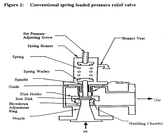
The basic spring loaded pressure Relief Valve has been developed to meet the need for a simple, reliable, system actuated device to provide overpressure protection.
The Valve consists of a Valve inlet or nozzle mounted on the pressurized system, a disc held against the nozzle to prevent flow under normal system operating conditions, a spring to hold the disc closed, and a body/Bonnet to contain the operating elements. The spring load is adjustable to vary the pressure at which the Valve will open.
When a pressure Relief Valve begins to lift, the spring force increases. Thus system pressure must increase if lift is to continue. For this reason pressure Relief Valves are allowed an overpressure allowance to reach full lift. This allowable overpressure is generally 10% for Valves on unfired systems. This margin is relatively small and some means must be provided to assist in the lift effort.
Most pressure Relief Valves, therefore, have a secondary control chamber or huddling chamber to enhance lift. As the disc begins to lift, fluid enters the control chamber exposing a larger area of the disc to system pressure.
This causes an incremental change in force which overcompensates for the increase in spring force and causes the Valve to open at a rapid rate. At the same time, the direction of the fluid flow is reversed and the momentum effect resulting from the change in flow direction further enhances lift. These effects combine to allow the Valve to achieve maximum lift and maximum flow within the allowable overpressure limits. Because of the larger disc area exposed to system pressure after the Valve achieves lift, the Valve will not close until system pressure has been reduced to some level below the set pressure. The design of the control chamber determines where the closing point will occur.
A safety Valve is a pressure Relief Valve actuated by inlet static pressure and characterized by rapid opening or pop action. (It is normally used for steam and air services.)
A low-lift safety Valve is a safety Valve in which the disc lifts automatically such that the actual discharge area is determined by the position of the disc.
A full-lift safety Valve is a safety Valve in which the disc lifts automatically such that the actual discharge area is not determined by the position of the disc.
A Relief Valve is a pressure relief device actuated by inlet static pressure having a gradual lift generally proportional to the increase in pressure over opening pressure. It may be provided with an enclosed spring housing suitable for closed discharge system application and is primarily used for liquid service.
A safety Relief Valve is a pressure Relief Valve characterized by rapid opening or pop action, or by opening in proportion to the increase in pressure over the opening pressure, depending on the application and may be used either for liquid or compressible fluid.
A conventional safety Relief Valve is a pressure Relief Valve which has its spring housing vented to the discharge side of the Valve. The operational characteristics (opening pressure, closing pressure, and relieving capacity) are directly affected by changes of the back pressure on the Valve.
A balanced safety Relief Valve is a pressure Relief Valve which incorporates means of minimizing the effect of back pressure on the operational characteristics (opening pressure, closing pressure, and relieving capacity).
A pilotoperated pressure Relief Valve is a pressure Relief Valve in which the major relieving device is combined with and is controlled by a self-actuated auxiliary pressure Relief Valve.
A poweractuated pressure Relief Valve is a pressure Relief Valve in which the major relieving device is combined with and controlled by a device requiring an external source of energy.
A temperature-actuated pressure Relief Valve is a pressure Relief Valve which may be actuated by external or internal temperature or by pressure on the inlet side.
A vacuum Relief Valve is a pressure relief device designed to admit fluid to prevent an excessive internal vacuum; it is designed to reclose and prevent further flow of fluid after normal conditions have been restored.
Many Codes and Standards are published throughout the world which address the design and application of pressure Relief Valves. The most widely used and recognized of these is the ASME Boiler and Pressure Vessel Code, commonly called the ASME Code.
is the calculated mass flow from an orifice having a cross sectional area equal to the flow area of the safety Valve without regard to flow losses of the Valve.
the pressure at which a Valve is set on a test rig using a test fluid at ambient temperature. This test pressure includes corrections for service conditions e.g. backpressure or high temperatures.
is the value of increasing static inlet pressure of a pressure Relief Valve at which there is a measurable lift, or at which the discharge becomes continuous as determined by seeing, feeling or hearing.
Because cleanliness is essential to the satisfactory operation and tightness of a safety Valve, precautions should be taken during storage to keep out all foreign materials. Inlet and outlet protectors should remain in place until the Valve is ready to be installed in the system. Take care to keep the Valve inlet absolutely clean. It is recommended that the Valve be stored indoors in the original shipping container away from dirt and other forms of contamination.
Safety Valves must be handled carefully and never subjected to shocks. Rough handling may alter the pressure setting, deform Valve parts and adversely affect seat tightness and Valve performance.
When it is necessary to use a hoist, the chain or sling should be placed around the Valve body and Bonnet in a manner that will insure that the Valve is in a vertical position to facilitate installation.
Many Valves are damaged when first placed in service because of failure to clean the connection properly when installed. Before installation, flange faces or threaded connections on both the Valve inlet and the vessel and/or line on which the Valve is mounted must be thoroughly cleaned of all dirt and foreign material.
Because foreign materials that pass into and through safety Valves can damage the Valve, the systems on which the Valves are tested and finally installed must also be inspected and cleaned. New systems in particular are prone to contain foreign objects that inadvertently get trapped during construction and will destroy the seating surface when the Valve opens. The system should be thoroughly cleaned before the safety Valve is installed.
The gaskets used must be dimensionally correct for the specific flanges. The inside diameters must fully clear the safety Valve inlet and outlet openings so that the gasket does not restrict flow.
For flanged Valves, draw down all connection studs or bolts evenly to avoid possible distortion of the Valve body. For threaded Valves, do not apply a wrench to the Valve body. Use the hex flats provided on the inlet bushing.
Safety Valves are intended to open and close within a narrow pressure range. Valve installations require accurate design both as to inlet and discharge piping. Refer to International, National and Industry Standards for guidelines.
The Valve should be mounted vertically in an upright position either directly on a nozzle from the pressure vessel or on a short connection fitting that provides a direct, unobstructed flow between the vessel and the Valve. Installing a safety Valve in other than this recommended position will adversely affect its operation.
Discharge piping should be simple and direct. A "broken" connection near the Valve outlet is preferred wherever possible. All discharge piping should be run as direct as is practicable to the point of final release for disposal. The Valve must discharge to a safe disposal area. Discharge piping must be drained properly to prevent the accumulation of liquids on the downstream side of the safety Valve.
The weight of the discharge piping should be carried by a separate support and be properly braced to withstand reactive thrust forces when the Valve relieves. The Valve should also be supported to withstand any swaying or system vibrations.
If the Valve is discharging into a pressurized system be sure the Valve is a "balanced" design. Pressure on the discharge of an "unbalanced" design will adversely affect the Valve performance and set pressure.
The Bonnets of balanced bellows safety Valves must always be vented to ensure proper functioning of the Valve and to provide a telltale in the event of a bellows failure. Do not plug these open vents. When the fluid is flammable, toxic or corrosive, the Bonnet vent should be piped to a safe location.
It is important to remember that a pressure Relief Valve is a safety device employed to protect pressure vessels or systems from catastrophic failure. With this in mind, the application of pressure Relief Valves should be assigned only to fully trained personnel and be in strict compliance with rules provided by the governing codes and standards.
One of the main reasons I have found for chattering of a safety valve is improper line sizing. Specifically, the inlet line to the safety valve. What"s happening is if the system sees an overpressure the safety valve opens (fully, assumes a true safety valve with huddling chamber). The valve will remain open as long as it is at app. 90% full capacity. If the line sizing restricts this flow the valve closes. Pressure builds, it opens fully. The process is cyclic and the rapid opening/closing prematurely wears down the valve nozzle and seat.
The valve pops on static pressure increase, the flow losses cause it to reseat before the system pressure (at the source has cleared) and the cycle repeats...
look for reducers, excessive bends and elbows, and valving in the inlet line. also look for long piping runs beteen the relief valve and the vessel or the pipe being protected.
I also encounter a lot of general industry plants that try to operate at or very near to the safety valve settings. It"s very common for the unknowing to select a safety valve that"s set for their operating pressure, and have it "feather". RE: Pressure Valve Chattering
you can take into account line and minor losses in system where PRV"s are installed, it would not be practicle to minimize line and minor losses only to cut the pressure loss you saved with the PRV valve.....
To take these into account you have to properly size the valve(S). I hinted to a big blunder I see often. A PRV may consist of more than one valve depending on what you are trying to accomplish....
Why not use a pilot operated PSV with the sensor located on the vessel (or whatever it is you"re trying to protect)? That should help with pressure drop on the inlet side. This may stop the chattering, but you may still have a problem if the line is too small, ie, the pipe and valve won"t pass enough fluid to bring the pressure down fast enough. RE: Pressure Valve Chattering
Or......if this is a steam pressure reducing valve, check out the catalog information for the Watts Model 152A which has an anti-chatter adjusting screw on the side. RE: Pressure Valve Chattering
Both Farris Engineering and Dresser Consolidated Troubleshooting Charts refer to Undersized Inlet Piping as a major cause of Chatter. A quote from Crosby, "A valve should never be installed on a fitting having a smaller inside diameter than the inlet connection of the valve."
According to API RP576, 5.2.c., "Improper or lengthy piping to the PRV inlet…can cause a PRV to chatter. The pressure under the seat may become great enough to open the PRV. However, as soon as the flow is established, the built-up pressure drop in the connecting piping may be so great that the pressure under the seat falls and allows the valve to close. A cycle of opening and closing may develop, become rapid, and subject the PRV Seating Surfaces to severe hammering, which damages the seating surfaces, sometimes beyond repair."
If you think about it logically, reducing the inlet piping or making it excessively long both have the same effect on the operation of a PRV as placing a large, high capacity PRV in a low volume application (oversizing). Basically there is insufficient volume to maintain the reaction force in the PRV Huddling Chamber necessary to overcome spring force.
The PRV is designed for a flow range, if the system cannot deliver that flow then the valve is oversized, no matter what the diameter and if you design only on daimeter without understanding the system, it is bound to fail...Volume of flow through the valve has nothing to do with its operation, its only the pressure that performs the work to modulate the valve.
I understand that Site Specific Engineering Solutions are preferable to a CODE which seeks consensus. However,I have been Setting & Testing Pressure Relief Valves for ASME Sec. I, Steam and for ASME Sec. VIII Steam, Air/Gas and Liquid Service for 30 years. I have tested on a range of Test Benches from small Test Rigs with no volume to Test Benches with 100 cu ft Test Vessels as well as on Power Boilers upto 2970 psi with Live Steam. My experience with the Performance of PRVs tested on Low Volume and then placed in High Flow Service Applications proves to me that Flow is as important to PRV Performance as Pressure.
I have known many of the members of ASME Sub-Committee Safety Valve Requirements for years, many are employees of PRV Manufacturers and all are very knowledgable. They take their Committee Work seriously and have written the requirements to reflect their collective experience.
All my comments are directed toward Pressure Relief Valves. I have no practical experience in Pressure Reducing applications and I began to wonder if that is why we seem to be in disagreement over some very basic issues.
For years the ASME Code referred to Safety-Relief Valves (SRV), but recently the National Board Inspection Code has attempted to change the term to Pressure Relief Valve (PRV).
sorry for the confusion, I reread your posts too....I was DEFINATELY not talking steam!!!! Nor relief valves.... LOL it is confusing and I wish we engineers would settle on terminology....I was talking pressure reducing service for fluids.....I was wrong not to quantify my response.....my comments only go for fluids for whoever is reading.....


 8613371530291