
huddling chamber safety valve brands

As soon as mankind was able to boil water to create steam, the necessity of the safety device became evident. As long as 2000 years ago, the Chinese were using cauldrons with hinged lids to allow (relatively) safer production of steam. At the beginning of the 14th century, chemists used conical plugs and later, compressed springs to act as safety devices on pressurised vessels.
Early in the 19th century, boiler explosions on ships and locomotives frequently resulted from faulty safety devices, which led to the development of the first safety relief valves.
In 1848, Charles Retchie invented the accumulation chamber, which increases the compression surface within the safety valve allowing it to open rapidly within a narrow overpressure margin.
Today, most steam users are compelled by local health and safety regulations to ensure that their plant and processes incorporate safety devices and precautions, which ensure that dangerous conditions are prevented.
The principle type of device used to prevent overpressure in plant is the safety or safety relief valve. The safety valve operates by releasing a volume of fluid from within the plant when a predetermined maximum pressure is reached, thereby reducing the excess pressure in a safe manner. As the safety valve may be the only remaining device to prevent catastrophic failure under overpressure conditions, it is important that any such device is capable of operating at all times and under all possible conditions.
Safety valves should be installed wherever the maximum allowable working pressure (MAWP) of a system or pressure-containing vessel is likely to be exceeded. In steam systems, safety valves are typically used for boiler overpressure protection and other applications such as downstream of pressure reducing controls. Although their primary role is for safety, safety valves are also used in process operations to prevent product damage due to excess pressure. Pressure excess can be generated in a number of different situations, including:
The terms ‘safety valve’ and ‘safety relief valve’ are generic terms to describe many varieties of pressure relief devices that are designed to prevent excessive internal fluid pressure build-up. A wide range of different valves is available for many different applications and performance criteria.
In most national standards, specific definitions are given for the terms associated with safety and safety relief valves. There are several notable differences between the terminology used in the USA and Europe. One of the most important differences is that a valve referred to as a ‘safety valve’ in Europe is referred to as a ‘safety relief valve’ or ‘pressure relief valve’ in the USA. In addition, the term ‘safety valve’ in the USA generally refers specifically to the full-lift type of safety valve used in Europe.
Pressure relief valve- A spring-loaded pressure relief valve which is designed to open to relieve excess pressure and to reclose and prevent the further flow of fluid after normal conditions have been restored. It is characterised by a rapid-opening ‘pop’ action or by opening in a manner generally proportional to the increase in pressure over the opening pressure. It may be used for either compressible or incompressible fluids, depending on design, adjustment, or application.
Safety valves are primarily used with compressible gases and in particular for steam and air services. However, they can also be used for process type applications where they may be needed to protect the plant or to prevent spoilage of the product being processed.
Relief valve - A pressure relief device actuated by inlet static pressure having a gradual lift generally proportional to the increase in pressure over opening pressure.
Relief valves are commonly used in liquid systems, especially for lower capacities and thermal expansion duty. They can also be used on pumped systems as pressure overspill devices.
Safety relief valve - A pressure relief valve characterised by rapid opening or pop action, or by opening in proportion to the increase in pressure over the opening pressure, depending on the application, and which may be used either for liquid or compressible fluid.
In general, the safety relief valve will perform as a safety valve when used in a compressible gas system, but it will open in proportion to the overpressure when used in liquid systems, as would a relief valve.
Safety valve- A valve which automatically, without the assistance of any energy other than that of the fluid concerned, discharges a quantity of the fluid so as to prevent a predetermined safe pressure being exceeded, and which is designed to re-close and prevent further flow of fluid after normal pressure conditions of service have been restored.
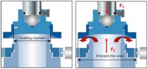
The pressure below the valve must increase above the set pressurebefore the safety valve reaches a noticeable lift. As a result of the restriction of flow between the disc and the adjusting ring, pressure builds up in the huddling chamber. The pressure now acts on an enlarged disc area. This increases the force Fp so that the additional spring force required to further compress the spring is overcome. The valve will open rapidly with a "pop", in most cases to its full lift.
Overpressure is the pressure increase above the set pressurenecessary for the safety valve to achieve full lift and capacity. The overpressure is usually expressed as a percentage of the set pressure. Codes and standards provide limits for the maximum overpressure. A typical value is 10%, ranging between 3% and 21% depending on the code and application.
Many electronic, pneumatic and hydraulic systems exist today to control fluid system variables, such as pressure, temperature and flow. Each of these systems requires a power source of some type, such as electricity or compressed air in order to operate. A pressure Relief Valve must be capable of operating at all times, especially during a period of power failure when system controls are nonfunctional. The sole source of power for the pressure Relief Valve, therefore, is the process fluid.
Once a condition occurs that causes the pressure in a system or vessel to increase to a dangerous level, the pressure Relief Valve may be the only device remaining to prevent a catastrophic failure. Since reliability is directly related to the complexity of the device, it is important that the design of the pressure Relief Valve be as simple as possible.
The pressure Relief Valve must open at a predetermined set pressure, flow a rated capacity at a specified overpressure, and close when the system pressure has returned to a safe level. Pressure Relief Valves must be designed with materials compatible with many process fluids from simple air and water to the most corrosive media. They must also be designed to operate in a consistently smooth and stable manner on a variety of fluids and fluid phases.
The basic spring loaded pressure Relief Valve has been developed to meet the need for a simple, reliable, system actuated device to provide overpressure protection.
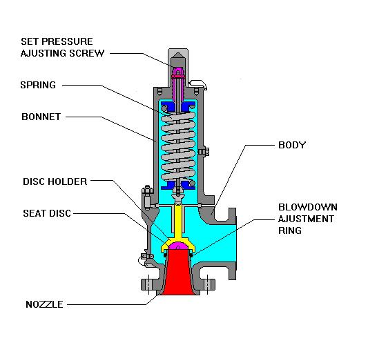
The Valve consists of a Valve inlet or nozzle mounted on the pressurized system, a disc held against the nozzle to prevent flow under normal system operating conditions, a spring to hold the disc closed, and a body/Bonnet to contain the operating elements. The spring load is adjustable to vary the pressure at which the Valve will open.
When a pressure Relief Valve begins to lift, the spring force increases. Thus system pressure must increase if lift is to continue. For this reason pressure Relief Valves are allowed an overpressure allowance to reach full lift. This allowable overpressure is generally 10% for Valves on unfired systems. This margin is relatively small and some means must be provided to assist in the lift effort.
Most pressure Relief Valves, therefore, have a secondary control chamber or huddling chamber to enhance lift. As the disc begins to lift, fluid enters the control chamber exposing a larger area of the disc to system pressure.
This causes an incremental change in force which overcompensates for the increase in spring force and causes the Valve to open at a rapid rate. At the same time, the direction of the fluid flow is reversed and the momentum effect resulting from the change in flow direction further enhances lift. These effects combine to allow the Valve to achieve maximum lift and maximum flow within the allowable overpressure limits. Because of the larger disc area exposed to system pressure after the Valve achieves lift, the Valve will not close until system pressure has been reduced to some level below the set pressure. The design of the control chamber determines where the closing point will occur.
A safety Valve is a pressure Relief Valve actuated by inlet static pressure and characterized by rapid opening or pop action. (It is normally used for steam and air services.)
A low-lift safety Valve is a safety Valve in which the disc lifts automatically such that the actual discharge area is determined by the position of the disc.
A full-lift safety Valve is a safety Valve in which the disc lifts automatically such that the actual discharge area is not determined by the position of the disc.
A Relief Valve is a pressure relief device actuated by inlet static pressure having a gradual lift generally proportional to the increase in pressure over opening pressure. It may be provided with an enclosed spring housing suitable for closed discharge system application and is primarily used for liquid service.
A safety Relief Valve is a pressure Relief Valve characterized by rapid opening or pop action, or by opening in proportion to the increase in pressure over the opening pressure, depending on the application and may be used either for liquid or compressible fluid.
A conventional safety Relief Valve is a pressure Relief Valve which has its spring housing vented to the discharge side of the Valve. The operational characteristics (opening pressure, closing pressure, and relieving capacity) are directly affected by changes of the back pressure on the Valve.
A balanced safety Relief Valve is a pressure Relief Valve which incorporates means of minimizing the effect of back pressure on the operational characteristics (opening pressure, closing pressure, and relieving capacity).
A pilotoperated pressure Relief Valve is a pressure Relief Valve in which the major relieving device is combined with and is controlled by a self-actuated auxiliary pressure Relief Valve.
A poweractuated pressure Relief Valve is a pressure Relief Valve in which the major relieving device is combined with and controlled by a device requiring an external source of energy.
A temperature-actuated pressure Relief Valve is a pressure Relief Valve which may be actuated by external or internal temperature or by pressure on the inlet side.
A vacuum Relief Valve is a pressure relief device designed to admit fluid to prevent an excessive internal vacuum; it is designed to reclose and prevent further flow of fluid after normal conditions have been restored.
Many Codes and Standards are published throughout the world which address the design and application of pressure Relief Valves. The most widely used and recognized of these is the ASME Boiler and Pressure Vessel Code, commonly called the ASME Code.
is the calculated mass flow from an orifice having a cross sectional area equal to the flow area of the safety Valve without regard to flow losses of the Valve.
the pressure at which a Valve is set on a test rig using a test fluid at ambient temperature. This test pressure includes corrections for service conditions e.g. backpressure or high temperatures.
is the value of increasing static inlet pressure of a pressure Relief Valve at which there is a measurable lift, or at which the discharge becomes continuous as determined by seeing, feeling or hearing.
Because cleanliness is essential to the satisfactory operation and tightness of a safety Valve, precautions should be taken during storage to keep out all foreign materials. Inlet and outlet protectors should remain in place until the Valve is ready to be installed in the system. Take care to keep the Valve inlet absolutely clean. It is recommended that the Valve be stored indoors in the original shipping container away from dirt and other forms of contamination.
Safety Valves must be handled carefully and never subjected to shocks. Rough handling may alter the pressure setting, deform Valve parts and adversely affect seat tightness and Valve performance.
When it is necessary to use a hoist, the chain or sling should be placed around the Valve body and Bonnet in a manner that will insure that the Valve is in a vertical position to facilitate installation.
Many Valves are damaged when first placed in service because of failure to clean the connection properly when installed. Before installation, flange faces or threaded connections on both the Valve inlet and the vessel and/or line on which the Valve is mounted must be thoroughly cleaned of all dirt and foreign material.
Because foreign materials that pass into and through safety Valves can damage the Valve, the systems on which the Valves are tested and finally installed must also be inspected and cleaned. New systems in particular are prone to contain foreign objects that inadvertently get trapped during construction and will destroy the seating surface when the Valve opens. The system should be thoroughly cleaned before the safety Valve is installed.
The gaskets used must be dimensionally correct for the specific flanges. The inside diameters must fully clear the safety Valve inlet and outlet openings so that the gasket does not restrict flow.
For flanged Valves, draw down all connection studs or bolts evenly to avoid possible distortion of the Valve body. For threaded Valves, do not apply a wrench to the Valve body. Use the hex flats provided on the inlet bushing.
Safety Valves are intended to open and close within a narrow pressure range. Valve installations require accurate design both as to inlet and discharge piping. Refer to International, National and Industry Standards for guidelines.
The Valve should be mounted vertically in an upright position either directly on a nozzle from the pressure vessel or on a short connection fitting that provides a direct, unobstructed flow between the vessel and the Valve. Installing a safety Valve in other than this recommended position will adversely affect its operation.
Discharge piping should be simple and direct. A "broken" connection near the Valve outlet is preferred wherever possible. All discharge piping should be run as direct as is practicable to the point of final release for disposal. The Valve must discharge to a safe disposal area. Discharge piping must be drained properly to prevent the accumulation of liquids on the downstream side of the safety Valve.
The weight of the discharge piping should be carried by a separate support and be properly braced to withstand reactive thrust forces when the Valve relieves. The Valve should also be supported to withstand any swaying or system vibrations.
If the Valve is discharging into a pressurized system be sure the Valve is a "balanced" design. Pressure on the discharge of an "unbalanced" design will adversely affect the Valve performance and set pressure.
The Bonnets of balanced bellows safety Valves must always be vented to ensure proper functioning of the Valve and to provide a telltale in the event of a bellows failure. Do not plug these open vents. When the fluid is flammable, toxic or corrosive, the Bonnet vent should be piped to a safe location.
It is important to remember that a pressure Relief Valve is a safety device employed to protect pressure vessels or systems from catastrophic failure. With this in mind, the application of pressure Relief Valves should be assigned only to fully trained personnel and be in strict compliance with rules provided by the governing codes and standards.
Because a safety valve is often the last device to prevent catastrophic failure under pressure conditions, it is important that the valve works at all times i.e. it must be 100% reliable.
Safety valves should be installed wherever the maximum allowable working pressure of a system or pressure containing vessel is likely to be exceeded, in particular under fault conditions due to the failure of another piece of equipment in the system.
The term “Safety Valve” and “Relief Valve” are generic terms to describe a variety of pressure relief devices. A wide range is available based on the application and required performance criteria. The different designs are required to meet numerous national standards.
The images below show the devastating results of a failed Safety valve (due to poor maintenace) or ones which have been incorrectly sized, installed or maintained.
A spring-loaded pressure relief valve which is designed to open to relieve excess pressure and to reclose and prevent the further flow of fluid after normal conditions have been restored. It is characterised by a rapid-opening "pop" action or by opening in a manner generally proportional to the increase in pressure over the opening pressure. It may be used for either compressible or incompressible fluids, depending on design, adjustment, or application.
Relief valve - A pressure relief device actuated by inlet static pressure having a gradual lift generally proportional to the increase in pressure over opening pressure.
Safety relief valve - A pressure relief valve characterised by rapid opening or pop action, or by opening in proportion to the increase in pressure over the opening pressure, depending on the application, and which may be used either for liquid or compressible fluid.
Safety valve - A valve which automatically, without the assistance of any energy other than that of the fluid concerned, discharges a quantity of the fluid so as to prevent a predetermined safe pressure being exceeded, and which is designed to re-close and prevent further flow of fluid after normal pressure conditions of service have been restored.
The images below show a standard Relief valve and a standard Safety valve from a well-known UK manufacturer. Each manufacturer does things slightly differently however all of the basic components and principles of operation are the same. As described previously, a safety valve differs from a relief valve in that it opens rapidly once the set pressure has been reached. For the same inlet size and with the valve in the closed position, the surface area that the pressure on the inlet side will see is the same. When the set pressure is reached and the valve starts to open, the disk on a Safety valve is larger (see the diagrams below) and hence the same pressure then sees a much larger surface area and consequently the force increases greatly causing the valve to open quickly and hence the characteristic pop action.
The image below shows the above Safety valves and Relief valves dismantled. The disk diameter on the 1" (DN25) Safety valve is only 7mm larger than on the Relief valve which doesnt sound like much, but when you calculate the areas it is an increase of 36%.
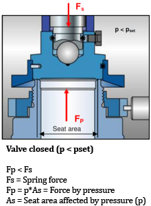
This diagram represents a Safety valve in its very simplest form. The force acting on the inlet side of the disk is acting against the force applied by the spring plus the force applied by the back pressure on the top of the disk.
The valve remains closed when(PI x Ab) < Fs + (PB x At), is in equilibrium when(PI x Ab) = Fs + (PB x At) and opens when(PI x Ab) > Fs + (PB x At) were PI = Inlet pressure, PB = Back pressure, At = Top of disk area, Ab = Bottom of disk area. Things to notice from this design are that if PB is variable and quite large relative to PI, then this will cause the pressure at which the valve opens to vary which is undesirable. The following two designs (Fig 3 & Fig 4) are available that eliminate the effect of back pressure on the set pressure.
The bellows prevents backpressure acting on the top side of the disk. In relation to the piston there is no top side within the main body of the valve hence again the back pressure cannot affect the set pressure. Bellows failure is an important concern in critical applications where a very precise set pressure is required. In these cases some mechanism to detect a leak of process medium out of the top vent would be implemented. Piston designs are not usually found in conventional Safety valves but are more common in Pilot Operated Safety valves.
API 520 Practice Guidelines: a conventional design should not typically be used when the built-up backpressure is greater than 10% of the set pressure at 10% over pressure. European standard EN ISO 4126: the built-up backpressure should be limited to 10% of the set pressure when the valve is discharging at the certified capacity.
Overpressure is the percentage over the set pressure by which the valve is fully open. The blowdown is the percentage below the set pressure by which the valve is fully closed.
The basic elements of the design are right angle pattern valve body, inlet can be either a full nozzle or a semi-nozzle type. With a full nozzle design has the “wetted” inlet tract formed from one piece (as per figure 6) with the seat integrated into the top of the nozzle. The internal bore of the nozzle and the disc is the only part of the valve that is exposed to the process fluid with the valve in the closed position. A semi-nozzle design consists of a seating ring fitted into the body.The disc is held onto the seat by the stem, with the downward force coming from the compression on the spring mounted in the bonnet. The amount of compression on the spring is adjusted by the spring adjuster under the cap.
Unless bellows or diaphragm sealing is used, process fluid will enter the spring housing (or bonnet). The amount of fluid depends on the particular design of safety valve. If emission of this fluid into the atmosphere is acceptable, the spring housing may be vented to the atmosphere - an open bonnet. This is usually advantageous when the safety valve is used on high temperature fluids or for boiler applications as, otherwise, high temperatures can relax the spring, altering the set pressure of the valve. However, using an open bonnet exposes the valve spring and internals to environmental conditions, which can lead to damage and corrosion of the spring.
When the fluid must be completely contained by the safety valve (and the discharge system), it is necessary to use a closed bonnet, which is not vented to the atmosphere. This type of spring enclosure is almost universally used for small screwed valves and, it is becoming increasingly common on many valve ranges since, particularly on steam, discharge of the fluid could be hazardous to personnel.
A lifting mechanism is recommended to test for correct valve operation at all times where corrosion, caking, or any deposit could prevent the opening operation.
Foreign particles can lodge under the seat of the valve when it discharges. The lifting lever allows you to lift the valve and flush the obstruction. Pressure relief valves for Section VIII require a lift lever on all air, steam, and hot water valves used at temperatures over 60 degC. Typically used where periodic testing of the valve in location is desired to assure its operation. With an Open lifting lever design, when the valve discharges, fluid media will escape into the atmosphere around the open lifting lever assembly. If this is not desirable or when back pressure is present you would select a Packed Lifting Lever design.
As described above, this type is selected where leakage of the media to the atmosphere during valve discharge or during back pressure would be un-desirable. A packed lever design is a completely sealed assembly.
Under certain circumstances i.e. under the start-up conditions of a plant or to pressure test the system in a controlled environment, it may be required that the valve is prevented from opening.This is achieved by screwing the bolt (shown on the wire) into the cap which screws down onto the stem and prevents it lifting. Obviously it is important that test gags are removed prior to placing the valve into service.
The bellows is designed to cover the same area on the back of the disc equal to the seat area hence the back pressure will have no effect on the set pressure. See the previous section “Basic Safety Valve Principles”. Bellows also protects the spindle, spindle guide and spring from the process medium.
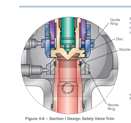
A disc is held against the nozzle by a spring, which is contained in a cast bonnet. The spring is adjusted by a compression screw to permit the calibration of opening or set pressure. An adjustable nozzle ring, threaded onto the nozzle, controls the geometry of the fluid exit control chamber (also known as a huddling chamber). The control chamber (huddling chamber) geometry is very important in controlling valve opening and closing pressures and stability of operation. The nozzle ring is locked into position by a ring pin assembly as shown in Figure 15 below.
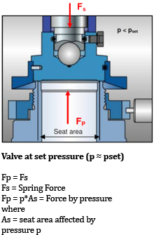
Under normal system operation the valve remains in the closed position because the spring force (Fs) is greater than the system pressure acting on the internal nozzle seating area (PA). If system pressure increases to a point when these forces are equal, then the set pressure is reached. The disc lifts and fluid flows through the valve. When pressure in the system returns to a safe level, the valve closes.
Just prior to reaching set point, the pressure relief valve leaks system fluid into the huddling chamber. The fluid now acts on a larger area of the disc inside the huddling chamber (PAh), causing the valve to experience an instantaneous increase in the opening force. Refer to the figure 16 above to see relationship between Nozzle Area (A) and the Huddling Chamber Area (Ah). System pressure acting on the larger area will suddenly open the safety relief valve at a rapid rate.
Although the opening is rapid and dramatic, the valve does not open fully at set point. The system pressure must increase above set point to open the valve to its full lift and capacity position. Maximum lift and certified flow rates will be achieved within the allowable limits (overpressure) established by various codes and standards. All pressure relief ales are allowed an overpressure allowance to reach full rated flow. The allowable over pressure can vary from 10% to 21% on unfired vessels and systems, depending on the sizing basis, number of valves, and whether a fire condition is encountered.
Once the valve has controlled the pressure excursion, system pressure will start to reduce. Since the huddling chamber area is now controlling the exit fluid flow, system pressure must reduce below the set point before the spring force is able to close the valve. The difference between the set pressure and the closing pressure is called blowdown, and is usually expressed as a percentage of set pressure. The typical blowdown can vary from 7% to 10%, the industry standard.
The nozzle ring adjustment changes the shape and volume of the huddling chamber, and its position will affect both the opening and the closing characteristics of the valve. When the nozzle ring is adjusted to its top position, the huddling chamber is restricted to its maximum. The valve will usually pop very distinctly with a minimum simmer (leakage before opening), but the blowdown will increase. When the nozzle ring is lowered to its lowest position, minimal restriction to the huddling chamber occurs. At this position, simmer increases and the blowdown decreases. The final ring position is somewhere between these two extremes to provide optimal performance.
On liquid service, a different dynamic situation exists. Liquids do not expand when flowing across orifices, and a small amount of fluid flow across the nozzle will produces a large local pressure drop at the nozzle orifice. This local pressure drop causes the spring to reclose the valve if the fluid flow is minimal. Liquids leaking into the huddling chamber can quickly drain out by gravity and prevent fluid pressure from building up in the secondary area of the huddling chamber. Liquid relief valves are thus susceptible to a phenomenon called chatter, especially at low fluid flow rates. Chatter is the rapid opening and closing of the pressure relief valve and is always destructive.
Because of the difference in the characteristics of gases and liquids, some valve designs require a special liquid trim in order to meet ASME Code Section VIII performance criteria of full rated liquid flow at 10% overpressure. With liquids since no visible or audible pop is heard at set point, the set pressure is defined as the pressure when the first heavy flow occurs (a pencil sized steady stream of water that remains unbroken for approximately one inch).
If you have a system that is shut down for annual maintenance then this is an ideal time to remove your Safety valves and have them inspected and recertified.
For systems that can only be off for short periods of time, it is sensible to keep a spare valve to swap over and then the removed valve can be inspected and recertified.
For systems that cannot be shut down, you will need to use a changeover valve which allows you to swap between Safety valves allowing one to be removed for inspection and testing.
For larger Safety valves on systems that run continuously, you may consider using in-situ testing. This method does have some limitations however since you cannot visually inspect the inside of the valve, but it will tell you if the valve is opening at the correct set pressure.
(a) A valve passing (leaking) on the outlet side when the valve is supposed to be closed. This can happen to valves of any age (new or old) and occurs if debris contained in the medium passes through the valve at a point when the valve lifts, and the debris either traps or damages the internals of the valve. On soft seated valves, hard particles may embed themselves in the soft material causing re-sealing issues. If your valve has a lifting lever and it is safe to do so, then it is worth lifting the handle for a few seconds which will hopefully clear any debris allowing the valve to reseal correctly. If this isn’t an option or it doesn’t cure the problem, then the valve will need to be removed and returned for maintenance and recertification. The time we often see this the most is during the startup of a system and there is a pressure spike, hence this is why it is extremely important that a system is flushed out well before hand.

A spring-loaded relief valve can be thought of as a spring /mass system which is why relief valves chatter. Researchers have found significant differences in the stability of relief valves based on the design of their internals. One recent study found that with 6 feet of inlet piping, valves from Manufacturer X were stable in 50% of the tests while valves from Manufacturer Z where stable in 100% of these tests.¹ Smith & Burgess Laboratory research has confirmed these findings. However, relief systems designers tend to downplay (if not ignore) the importance of the mechanical design of relief valves which is important to stability. Therefore, this article discusses the fundamentals of the design parameters for the internals of a relief valve. The intent is to provide design considerations and general operation information for use by relief systems designers, specifically assisting with the understanding of the effects of valve design on stability.
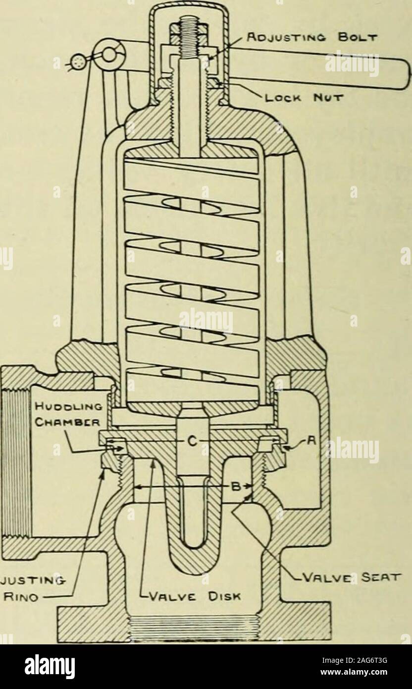
Modern relief valves are wonderfully modular.The internal parts for a relief valve (valve disc,disc holder, blowdown ringandspring) can be interchanged for ones with a different design to customize valve performance based on the application, fluid service, and set pressure.Valve disccan be metal-to-metal or soft seats. Soft seat designs use an elastomer to create a better seal between thevalvediscand thenozzle. Relief valves with elastomer seats have limitations and can only be used in certain applications.Disc holdersare generally designed to allow thevalve discto float which provides an angular movement that reduces seat leakage from minor misalignments (ensuring that thevalve dischas 360 degrees of contact with thenozzle). Thedisc holderoutside diameter, shape and thickness plays an important role in determining the valve performance by defining the shape of thehuddling chamber. Thehuddling chambercan also be defined by theblowdown ring(s). Thering(s)can also be swapped to different sized and shapedringsto adjust performance based on the expected relief fluid.Springsare selected to keep the valve closed and must fit inside thevalve bonnet. The force thespringexerts is an important design criteria for a relief device and varies depending on the relief fluid, valve size and set pressure.
Spring loaded relief valves are known as "pop action" relief valves as they typically pop open at their set pressure. Initially, the pressure differential across thevalve discthat creates the force to over come the spring force and open the valve.The pop action occurs because mosthuddling chambersare designed with an area that is approximately 10%-30% larger than thevalve seat(as thedisc holderis bigger than thevalve disc). Once the pressure under the seat is enough to lift thevalve discoff thenozzle, there is a step change in the upward forces on thespringand the valve "pops" open. The shape of thehuddling chamber(created by the shape and size of thedisc holder), the position and shape of theblowdown ring, and the characteristics of the fluid being relieved together determine the initial opening force and the initial lift of the valve.
Blowdown ringsare adjustable rings with a design shape that modifies the effluent flow path andhuddling chamberbased on the position. For process valves, a singleblowdown ringis typically threaded onto thenozzleand can be adjusted vertically up or down. Manufacturers will specify a recommended position relative to contact with thevalve disc. The position of theblowdown ringis fixed with a locking screw. The position of theblowdown ringchanges the blowdown (or reseat) pressure. For valves with a singleblowdown ring, the closer theblowdown ringis to thenozzle, the lower the pressure in the system will need to be for the valve to close (more blowdown). Other relief valves have multipleblowdown rings. Each manufacturer designs a uniqueblowdown ringto compliment other aspects of the relief valve design. Smith & Burgess" testing confirms that position and design ofblowdown ring(s)affects valve stability.
Relief Valve manufactures generally select aspringthat is designed for the set pressure of the valve. Thespringthat is selected will have a pressure range that thespringcan be applied. In many cases, there may be more than onespringthat can be used with each relief valve each having a different spring constant. The stifferspringmay have a range that is higher than the softerspringbut still meet the overall requirements for set pressure. The selection of thespringwill affect stability as the specific spring influences the natural frequency of the valve and can also affect the blowdown.
Think about the physics of what the huddling chamber does, and how it does it. Then it will all make perfect sense. The whole purpose of the huddling chamber is accelerate the opening of the valve....to get the valve into a high left position more quickly. The huddling chamber puts the "pop" into "pop valves". A consequence or trade-off is that it also makes the valve harder to re-close (blowdown).
The huddling chamber accelerates the PSV opening by creating a "secondary orifice". It"s easier to visualize this phenomenon if we talk about a gas (compressible fluid) application. As the gas flows through the primary orifice it then flows through the huddling chamber. At the exit of the huddling chamber the gas is pinched as it passes through the gap created by the blowdown adjustment ring (also referred to as the "nozzle ring"). The pressure on the upstream side of this gap (inside the huddling chamber) is acting on all surfaces, but notice that there"s a lot more surface area on the upper side than the lower side. Thus, this pressure creates additional lifting force, helping the valve get to a higher lift position.
When the gap at the outlet of the huddling chamber is reduced, the blowdown increases. The reduced gap causes a slightly higher pressure in the huddling chamber, thus increasing the lifting force (which necessarily impedes the re-closing of the valve). One can reduce the gap by either lowering the upper piece or raising the lower piece (blowdown adjustment ring).

Pressure Relief Valves – Pressure equipment requires protection from over pressurisation. A common way to protect vessels is the installation of a pressure relief valve. A pressure relief device is actuated by inlet static pressure and designed to open during an emergency or abnormal conditions to prevent a rise of internal fluid pressure above the specified design value. This device may also be designed to avoid an internal vacuum.
The sizing of valves is very important. To find out what happens if this is not done correctly, have a look at this article. Equally important to the design of the valve, is the in-service inspection and maintenance. The Health and safety Pressure System guide also highlights the need to have safety valves in place.
Common examples of these types include; direct spring-loaded pressure relief valves, pilot-operated pressure-relief valves, rupture disks, weight-loaded devices and pressure and/or vacuum vent valves.
A pressure relief valve (PRV) is designed to open for the relief of excess pressure and reclose, thereby preventing further flow after normal conditions have been restored. A PRV may be used for either compressible or incompressible fluids, depending on the design, adjustment or application.
Therefore, PRV is a general term, including safety valves, relief valves, conventional safety relief valves, balanced safety relief valves, and pilot-operated relief valves. The names ‘safety’ and ‘relief’ are frequently used interchangeably, but they should not be.
Safety valves are for compressible fluids, steam and other gases. This compressibility demands quick overpressure relief. So, safety valves have pop seats and plugs which open rapidly on overpressure, relieving at full flow. They may discharge steam into the atmosphere or direct a gas back to the system.
Relief valves are for non-compressible fluids-liquids such as water and oil. Immediate full-flow discharge is unnecessary since a minimal flow significantly reduces overpressure, so the plug and seat open and close very slowly, discharging back to some low-pressure point in the system to conserve the liquid.
A relief valve is a spring-loaded pressure relief valve actuated by the static pressure upstream of the valve. The valve opens typically in proportion to the pressure increase over the opening pressure. A relief valve is used primarily with non-compressible fluids.
A safety valve is a spring-loaded pressure relief valve actuated by the static pressure upstream of the valve and characterised by rapid opening or pop action. A safety valve is generally used with compressible fluids.
The oldest and the most commonly used type of PSV is the direct-acting type. They are designed as direct-acting because the force element that keeps the valve closed is either a weight, a spring or a combination of both. The process to be relieved acts directly on a disc that is held closed by the spring force opposing the lifting process pressure.
The image below shows the construction of a conventional spring-loaded PSV. The valve consists of a valve inlet or nozzle mounted on the pressurised system, a disc held against the nozzle to prevent flow under typical system operating conditions, a spring to hold the disc closed, and a body and bonnet to contain the operating elements.
The spring load is adjustable to vary the pressure at which the valve will open; when PSV begins to lift, the spring force increases. Thus, system pressure must increase if the lift is to continue. For this reason, pressure relief valves are allowed an overpressure allowance to reach full lift. This allowable overpressure is generally 10% for valves on unfired systems.
This margin is relatively small, and some means must be provided to assist in the lift effort. Most pressure relief valves, therefore, have a secondary control chamber or huddling chamber to enhance lift. As the disc begins to lift, fluid enters the control chamber, exposing a larger surface area for the pressure to act against.
This causes an incremental change in force that overcompensates for the increase in spring force and causes the valve to open rapidly. At the same time, the direction of the fluid flow is reversed, and the momentum effect resulting from the change in flow direction further enhances lift.
These effects combine to allow the valve to achieve maximum lift and maximum flow within the allowable overpressure limits. However, because the larger disc area is exposed to system pressure after the valve achieves lift, the valve will not close until system pressure has been reduced to some level below the set pressure. The design of the control chamber determines where the closing point will occur.
Force is equal to Pressure x Area.Therefore, the huddling chamber allows an increase in force by increasing the area by which the force can be exposed and applied, enhancing the lift.
Once normal operating conditions have been restored, the valve is required to close again, but since the larger area of the disc is still exposed to the fluid, the valve will not close until the pressure has dropped below the original set pressure.
Pressure relief valves on clean, non-toxic, non-corrosive systems may be vented directly to the atmosphere. Pressure relief valves on corrosive, toxic or valuable, recoverable fluids are vented into closed systems.
For valves installed in a closed system or when a long vent pipe is used, there is a possibility of developing high backpressure. Therefore, the back pressure on a PRV must always be evaluated, and its effect on valve performance and relieving capacity must be considered.
Superimposed backpressure may result from the valve outlet being connected to a normally pressurised system or caused by other pressure relief valves venting into a common header. Compensation for superimposed backpressure, which is constant, may be provided by reducing the spring force.
A pilot-operated pressure relief valve is a pressure relief valve in which the major relieving device is combined with and is controlled by a self-actuated auxiliary pressure relief valve.
Rupture discs are safety devices with a defined breaking point, which respond to a specific pressure and are used for pressure relief in the most diverse applications. They are used to protect against overpressure or vacuum within a process.
Rupture discs are either installed directly between flanges or inserted into a corresponding rupture disc holder, then mounted between flanges. Although they are often used to protect the inlet of a PRV from corrosive service conditions, they should be non-fragmenting to prevent damage to the valve when used in this service.
Stripdown and Inspection: Participants will be involved in the ‘as received’ lift test, strip down, inspection, assessment and reporting on the condition of the valve. We can supply sample used valves for use during the course if required.
Reassemble and Testing: During this phase of the course, the delegates will have the opportunity to conduct seat lapping and surface finish assessment. In addition, instruction will be given on the reassembly of the valve and the testing.
If you don’t know your blow down from your pop action, NASVI has you covered. Here is a handy cheat sheet on safety valve lingo and how to accurately order them.
SAFETY RELIEF VALVE:Safety relief valves are basically like pop safety valves and are primarily for liquid service where the thermal expansion in a liquid-laden vessel actuates the valve. When vapor is generated in these vessels, due to uncontrolled heat input, this valve with the huddling chamber, will give a high disc lift and discharge the expanded vapors. This valve is also suitable for gas or vapor service.
SELECTION OF VALVE:Valves should be selected for the particular installation on which they are to be used and also on the basis of the rated discharge capacity. This should be equal to or greater than the maximum output of the system.
INSTALLATION:The valve is to be installed in a vertical position, into a clean fitting, using the proper size and type of wrench so as not to damage the valve. The discharge piping, without stop valves, shall be independently supported and sloped downward slightly to drain condensate.

A spring-loaded pressure relief valve, also known as a “POP” type safety valve, is use in many industries to protect from over pressurizing of vessels, pipes, and containers. Conventional and balance bellows relief valves are the types of spring-loaded pressure relief valves. Codes and standards like IBR, ASME, API, etc require that these pressure relief valves are size to have a reliable capacity that is enough to maintain the integrity of the system by stopping the internal pressure from exceeding the design limits. The spring load pressure safety valves are design and select by the pressure relief system engineers to meet process-engineering requirements.
A spring-loaded pressure relief valve can assume as a spring/mass system which is the cause of relief valve chattering. Academics have found noticeable differences in the stability of safety valves based on internal constructions. In a study, the researchers found that with 6 feet of inlet piping, valves from manufacturer X were stable in 50% of the tests while valves from manufacturer Z were stable in 100% of these tests. However, relief systems engineers tend to downplay the value of the mechanical design of pressure relief valves which are important to stability. Because of this, this article especially discusses the fundamentals of the design parameters for the inner parts of a relief valve. The intention is to employ design considerations and general operation information for use by relief system engineers. Specifically assisting with the knowledge of the effects of valve design on stability.
Spring-loaded Pressure Relief Valves are also known as “POP type safety Valves”. This valve typically pops open at its set pressure. In the beginning, the pressure differential around the valve disc produces the force to overcome the spring force and open the valve. The pop movement came out because most huddling chambers are design with an area that is almost 10% to 30% larger than the valve seat. When the pressure under the seat would be enough to lift the valve disc off the nozzle, there would be a step change in the upward forces on the spring and the valve “pops” open. The shape of the huddling chamber which is created by the shape and size of the disc holder, the position and shape of the blowdown ring, and the characteristics of the fluid being relieved together determine the initial opening force and the initial lift of the valve. To read information about all types of valves click on Aira Blog.
The “POP” type safety valves should be IBR approved for the Indian market. IBR is a short form of Indian Boiler Regulation. The IBR has set the standard design and pressure range for the safety valve to sell in Indian markets. All manufacturers who are selling their safety valves in India should make valves that fit their criteria. Aira Euro Automation pvt. ltd. is an India-based industrial valve manufacturer that follows all criteria of IBR including API, CE, ATEX, etc.

Safety Relief Valve are normally used for liquid service, although safety valves may also be used. Ordinary relief valves do not have an accentuated huddling chamber nor a regular ring for varying or adjusting blowdown they therefore operate with a relatively lazy motion, slowly opening or closing as pressure increases or decreases. Such reliving action affords suitable protection for vessels or systems where there is no need for instaeous release of large volumes, and where sufficient leeway is provided between the design pressure and operating pressure in the system.
The Pressure Safety Valve Inspection article provides you information about inspection of pressure safety valve and pressure safety valve test in manufacturing shop as well as in operational plants.
Your pressure safety valve is a direct spring-loaded pressure-relief valve that is opened by the static pressure upstream of the valve and characterized by rapid opening or pop action.
Your construction code for pressure safety valve is API Standard 526 and covers the minimum requirements for design, materials, fabrication, inspection, testing, and commissioning.
These are:API Recommended Practice 520 for Sizing and SelectionAPI Recommended practice 521 Guideline for Pressure Relieving and Depressing SystemsAPI Recommended Practice 527 Seat Tightness of Pressure Relief Valves
For example if there is pressure vessel need to be installed in the state of Minnesota then the pressure vessel nameplate shall be U stamped and pressure vessel safety valve shall be UV stamped.
National Board Inspection Code (NBIC) have own certification scheme for pressure safety valves and using NB symbol. The NBIC code book for this certification is NB 18.
There are some other standards and codes which are used in pressure safety valve such as:ASME PTC 25 for pressure relief devices which majorly is used for assessment of testing facility and apparatus for safety valvesBS EN ISO 4126-1, 4126-2 and 4126-3 which is construction standard similar to API STD 526.
This API RP 527 might be used in conjunction of API RP 576 as testing procedure for seat tightness testing of pressure safety valve for periodical servicing and inspection.
These are only important points or summery of points for pressure safety valve in-service inspection and should not be assumed as pressure safety valve inspection procedure.
Pressure safety valve inspection procedure is comprehensive document which need to cover inspection methods to be employed, equipment and material to be used, qualification of inspection personnel involved and the sequence of the inspection activities as minimum.
You may use following content as summery of points for Pressure Safety Valve Inspection in operational plantDetermination pressure safety valve inspection interval based API STD 510 and API RP 576 requirementsInspection of inlet and outlet piping after pressure safety valve removal for any foulingInspection of pressure safety valve charge and discharge nozzles for possible deposit and corrosion productsTaking care for proper handling of pressure safety valves from unit to the valve shop. The detail of handling and transportation instruction is provided in API RP 576.Controlling of seals for being intact when the valves arrived to the valve shop.Making as received POP test and recording the relieving pressure.
If the POP pressure is higher than the set pressure the test need to be repeated and if in the second effort it was near to the set pressure it is because of deposit.If in the second effort it was not opened near to the set pressure either it was set wrongly or it was changed during the operationIf the pressure safety valve was not opened in 150% of set pressure it should be considered as stuck shut.If the pressure safety valve was opened below the set pressure the spring is weakenedMaking external visual inspection on pressure safety valve after POP test. The test need contain following item as minimum;the flanges for pitting and roughness
Making body wall thickness measurementDismantling of pressure safety valve if the result of as received POP test was not satisfactoryMaking detail and comprehensive visual and dimensional inspection on the dismantled valve parts (after cleaning)Making special attention to the dismantled valves seating surfaces inspection e.g. disk and seat for roughness, wear and damage which might cause valve leakage in serviceReplacing the damaged parts in dismantled valves based manufacture recommendation and API RP 576 requirementsMaking precise setting of the pressure safety valve after reassembly based manufacture recommendation or NB-18 requirements
Making at least two POP test after setting and making sure the deviation from set pressure is not more than 2 psi for valves with set pressure equal or less than 70 psi or 3% for valves with set pressure higher than 70 psiMaking valve tightness test for leakage purpose after approval of the setting pressure and POP tests. The test method and acceptance criteria must be according to the API RP 576.The API RP 527 also can be used for pressure safety valve tightness test.Recording and maintaining the inspection and testing results.


 8613371530291