
huddling chamber safety valve price
Because a safety valve is often the last device to prevent catastrophic failure under pressure conditions, it is important that the valve works at all times i.e. it must be 100% reliable.
Safety valves should be installed wherever the maximum allowable working pressure of a system or pressure containing vessel is likely to be exceeded, in particular under fault conditions due to the failure of another piece of equipment in the system.
The term “Safety Valve” and “Relief Valve” are generic terms to describe a variety of pressure relief devices. A wide range is available based on the application and required performance criteria. The different designs are required to meet numerous national standards.
The images below show the devastating results of a failed Safety valve (due to poor maintenace) or ones which have been incorrectly sized, installed or maintained.
A spring-loaded pressure relief valve which is designed to open to relieve excess pressure and to reclose and prevent the further flow of fluid after normal conditions have been restored. It is characterised by a rapid-opening "pop" action or by opening in a manner generally proportional to the increase in pressure over the opening pressure. It may be used for either compressible or incompressible fluids, depending on design, adjustment, or application.
Relief valve - A pressure relief device actuated by inlet static pressure having a gradual lift generally proportional to the increase in pressure over opening pressure.
Safety relief valve - A pressure relief valve characterised by rapid opening or pop action, or by opening in proportion to the increase in pressure over the opening pressure, depending on the application, and which may be used either for liquid or compressible fluid.
Safety valve - A valve which automatically, without the assistance of any energy other than that of the fluid concerned, discharges a quantity of the fluid so as to prevent a predetermined safe pressure being exceeded, and which is designed to re-close and prevent further flow of fluid after normal pressure conditions of service have been restored.
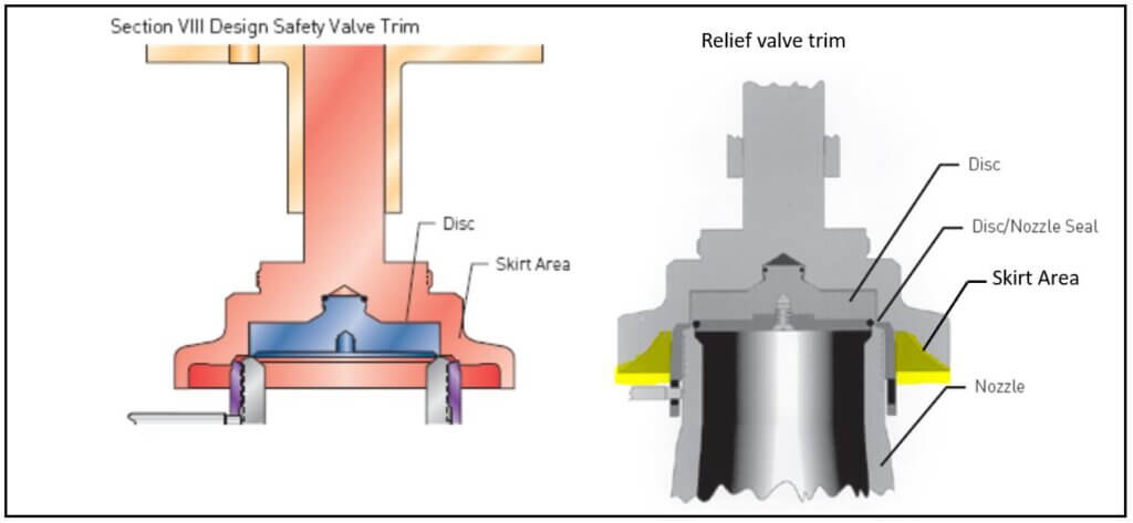
The images below show a standard Relief valve and a standard Safety valve from a well-known UK manufacturer. Each manufacturer does things slightly differently however all of the basic components and principles of operation are the same. As described previously, a safety valve differs from a relief valve in that it opens rapidly once the set pressure has been reached. For the same inlet size and with the valve in the closed position, the surface area that the pressure on the inlet side will see is the same. When the set pressure is reached and the valve starts to open, the disk on a Safety valve is larger (see the diagrams below) and hence the same pressure then sees a much larger surface area and consequently the force increases greatly causing the valve to open quickly and hence the characteristic pop action.
The image below shows the above Safety valves and Relief valves dismantled. The disk diameter on the 1" (DN25) Safety valve is only 7mm larger than on the Relief valve which doesnt sound like much, but when you calculate the areas it is an increase of 36%.
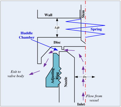
This diagram represents a Safety valve in its very simplest form. The force acting on the inlet side of the disk is acting against the force applied by the spring plus the force applied by the back pressure on the top of the disk.
The valve remains closed when(PI x Ab) < Fs + (PB x At), is in equilibrium when(PI x Ab) = Fs + (PB x At) and opens when(PI x Ab) > Fs + (PB x At) were PI = Inlet pressure, PB = Back pressure, At = Top of disk area, Ab = Bottom of disk area. Things to notice from this design are that if PB is variable and quite large relative to PI, then this will cause the pressure at which the valve opens to vary which is undesirable. The following two designs (Fig 3 & Fig 4) are available that eliminate the effect of back pressure on the set pressure.
The bellows prevents backpressure acting on the top side of the disk. In relation to the piston there is no top side within the main body of the valve hence again the back pressure cannot affect the set pressure. Bellows failure is an important concern in critical applications where a very precise set pressure is required. In these cases some mechanism to detect a leak of process medium out of the top vent would be implemented. Piston designs are not usually found in conventional Safety valves but are more common in Pilot Operated Safety valves.
API 520 Practice Guidelines: a conventional design should not typically be used when the built-up backpressure is greater than 10% of the set pressure at 10% over pressure. European standard EN ISO 4126: the built-up backpressure should be limited to 10% of the set pressure when the valve is discharging at the certified capacity.
Overpressure is the percentage over the set pressure by which the valve is fully open. The blowdown is the percentage below the set pressure by which the valve is fully closed.
The basic elements of the design are right angle pattern valve body, inlet can be either a full nozzle or a semi-nozzle type. With a full nozzle design has the “wetted” inlet tract formed from one piece (as per figure 6) with the seat integrated into the top of the nozzle. The internal bore of the nozzle and the disc is the only part of the valve that is exposed to the process fluid with the valve in the closed position. A semi-nozzle design consists of a seating ring fitted into the body.The disc is held onto the seat by the stem, with the downward force coming from the compression on the spring mounted in the bonnet. The amount of compression on the spring is adjusted by the spring adjuster under the cap.
Unless bellows or diaphragm sealing is used, process fluid will enter the spring housing (or bonnet). The amount of fluid depends on the particular design of safety valve. If emission of this fluid into the atmosphere is acceptable, the spring housing may be vented to the atmosphere - an open bonnet. This is usually advantageous when the safety valve is used on high temperature fluids or for boiler applications as, otherwise, high temperatures can relax the spring, altering the set pressure of the valve. However, using an open bonnet exposes the valve spring and internals to environmental conditions, which can lead to damage and corrosion of the spring.
When the fluid must be completely contained by the safety valve (and the discharge system), it is necessary to use a closed bonnet, which is not vented to the atmosphere. This type of spring enclosure is almost universally used for small screwed valves and, it is becoming increasingly common on many valve ranges since, particularly on steam, discharge of the fluid could be hazardous to personnel.
A lifting mechanism is recommended to test for correct valve operation at all times where corrosion, caking, or any deposit could prevent the opening operation.
Foreign particles can lodge under the seat of the valve when it discharges. The lifting lever allows you to lift the valve and flush the obstruction. Pressure relief valves for Section VIII require a lift lever on all air, steam, and hot water valves used at temperatures over 60 degC. Typically used where periodic testing of the valve in location is desired to assure its operation. With an Open lifting lever design, when the valve discharges, fluid media will escape into the atmosphere around the open lifting lever assembly. If this is not desirable or when back pressure is present you would select a Packed Lifting Lever design.
As described above, this type is selected where leakage of the media to the atmosphere during valve discharge or during back pressure would be un-desirable. A packed lever design is a completely sealed assembly.
Under certain circumstances i.e. under the start-up conditions of a plant or to pressure test the system in a controlled environment, it may be required that the valve is prevented from opening.This is achieved by screwing the bolt (shown on the wire) into the cap which screws down onto the stem and prevents it lifting. Obviously it is important that test gags are removed prior to placing the valve into service.
The bellows is designed to cover the same area on the back of the disc equal to the seat area hence the back pressure will have no effect on the set pressure. See the previous section “Basic Safety Valve Principles”. Bellows also protects the spindle, spindle guide and spring from the process medium.
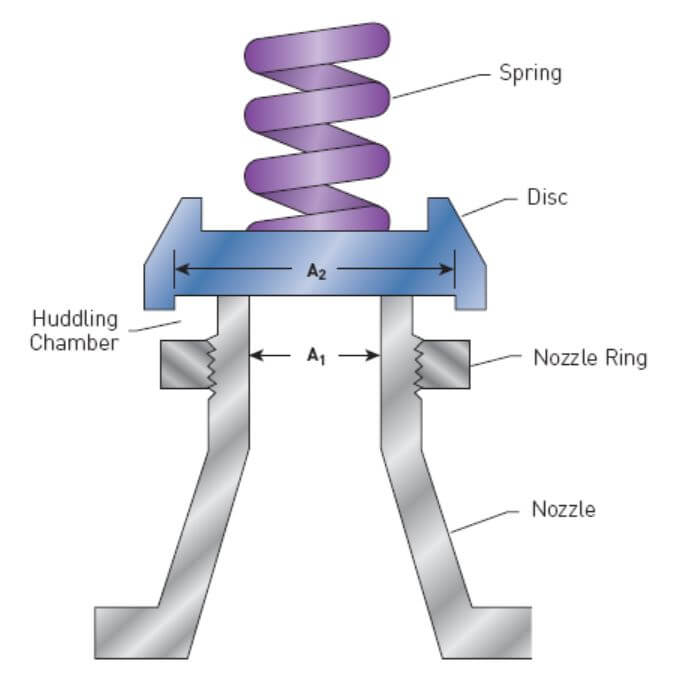
A disc is held against the nozzle by a spring, which is contained in a cast bonnet. The spring is adjusted by a compression screw to permit the calibration of opening or set pressure. An adjustable nozzle ring, threaded onto the nozzle, controls the geometry of the fluid exit control chamber (also known as a huddling chamber). The control chamber (huddling chamber) geometry is very important in controlling valve opening and closing pressures and stability of operation. The nozzle ring is locked into position by a ring pin assembly as shown in Figure 15 below.
Under normal system operation the valve remains in the closed position because the spring force (Fs) is greater than the system pressure acting on the internal nozzle seating area (PA). If system pressure increases to a point when these forces are equal, then the set pressure is reached. The disc lifts and fluid flows through the valve. When pressure in the system returns to a safe level, the valve closes.
Just prior to reaching set point, the pressure relief valve leaks system fluid into the huddling chamber. The fluid now acts on a larger area of the disc inside the huddling chamber (PAh), causing the valve to experience an instantaneous increase in the opening force. Refer to the figure 16 above to see relationship between Nozzle Area (A) and the Huddling Chamber Area (Ah). System pressure acting on the larger area will suddenly open the safety relief valve at a rapid rate.
Although the opening is rapid and dramatic, the valve does not open fully at set point. The system pressure must increase above set point to open the valve to its full lift and capacity position. Maximum lift and certified flow rates will be achieved within the allowable limits (overpressure) established by various codes and standards. All pressure relief ales are allowed an overpressure allowance to reach full rated flow. The allowable over pressure can vary from 10% to 21% on unfired vessels and systems, depending on the sizing basis, number of valves, and whether a fire condition is encountered.
Once the valve has controlled the pressure excursion, system pressure will start to reduce. Since the huddling chamber area is now controlling the exit fluid flow, system pressure must reduce below the set point before the spring force is able to close the valve. The difference between the set pressure and the closing pressure is called blowdown, and is usually expressed as a percentage of set pressure. The typical blowdown can vary from 7% to 10%, the industry standard.
The nozzle ring adjustment changes the shape and volume of the huddling chamber, and its position will affect both the opening and the closing characteristics of the valve. When the nozzle ring is adjusted to its top position, the huddling chamber is restricted to its maximum. The valve will usually pop very distinctly with a minimum simmer (leakage before opening), but the blowdown will increase. When the nozzle ring is lowered to its lowest position, minimal restriction to the huddling chamber occurs. At this position, simmer increases and the blowdown decreases. The final ring position is somewhere between these two extremes to provide optimal performance.
On liquid service, a different dynamic situation exists. Liquids do not expand when flowing across orifices, and a small amount of fluid flow across the nozzle will produces a large local pressure drop at the nozzle orifice. This local pressure drop causes the spring to reclose the valve if the fluid flow is minimal. Liquids leaking into the huddling chamber can quickly drain out by gravity and prevent fluid pressure from building up in the secondary area of the huddling chamber. Liquid relief valves are thus susceptible to a phenomenon called chatter, especially at low fluid flow rates. Chatter is the rapid opening and closing of the pressure relief valve and is always destructive.
Because of the difference in the characteristics of gases and liquids, some valve designs require a special liquid trim in order to meet ASME Code Section VIII performance criteria of full rated liquid flow at 10% overpressure. With liquids since no visible or audible pop is heard at set point, the set pressure is defined as the pressure when the first heavy flow occurs (a pencil sized steady stream of water that remains unbroken for approximately one inch).
If you have a system that is shut down for annual maintenance then this is an ideal time to remove your Safety valves and have them inspected and recertified.
For systems that can only be off for short periods of time, it is sensible to keep a spare valve to swap over and then the removed valve can be inspected and recertified.
For systems that cannot be shut down, you will need to use a changeover valve which allows you to swap between Safety valves allowing one to be removed for inspection and testing.
For larger Safety valves on systems that run continuously, you may consider using in-situ testing. This method does have some limitations however since you cannot visually inspect the inside of the valve, but it will tell you if the valve is opening at the correct set pressure.
(a) A valve passing (leaking) on the outlet side when the valve is supposed to be closed. This can happen to valves of any age (new or old) and occurs if debris contained in the medium passes through the valve at a point when the valve lifts, and the debris either traps or damages the internals of the valve. On soft seated valves, hard particles may embed themselves in the soft material causing re-sealing issues. If your valve has a lifting lever and it is safe to do so, then it is worth lifting the handle for a few seconds which will hopefully clear any debris allowing the valve to reseal correctly. If this isn’t an option or it doesn’t cure the problem, then the valve will need to be removed and returned for maintenance and recertification. The time we often see this the most is during the startup of a system and there is a pressure spike, hence this is why it is extremely important that a system is flushed out well before hand.

We VeeKay Process Instrumentsare manufacturer and exporter and our company is backed by an industry experience of 28 years and we offer process Control Instruments, Instrumentation Equipment, Boiler Accessories, Pipe Line Strainer, Pipe line View Glass/ Flow Indicators and Industrial Products. Apart from this, We also offer Level Gauges, Level Switches, Stainless Steel Strainers, Pipe Strainers, Basket Strainers, Duplex Type Strainer, Self Cleaning Strainer, Temporary Strainer, Flame Arrestor, Inline Endline, Custom Design Strainer Safety Valves. These are widely used across the oil, sugar, paper, steel power, pharma and chemical, industries.
Many electronic, pneumatic and hydraulic systems exist today to control fluid system variables, such as pressure, temperature and flow. Each of these systems requires a power source of some type, such as electricity or compressed air in order to operate. A pressure Relief Valve must be capable of operating at all times, especially during a period of power failure when system controls are nonfunctional. The sole source of power for the pressure Relief Valve, therefore, is the process fluid.
Once a condition occurs that causes the pressure in a system or vessel to increase to a dangerous level, the pressure Relief Valve may be the only device remaining to prevent a catastrophic failure. Since reliability is directly related to the complexity of the device, it is important that the design of the pressure Relief Valve be as simple as possible.
The pressure Relief Valve must open at a predetermined set pressure, flow a rated capacity at a specified overpressure, and close when the system pressure has returned to a safe level. Pressure Relief Valves must be designed with materials compatible with many process fluids from simple air and water to the most corrosive media. They must also be designed to operate in a consistently smooth and stable manner on a variety of fluids and fluid phases.
The basic spring loaded pressure Relief Valve has been developed to meet the need for a simple, reliable, system actuated device to provide overpressure protection.
The Valve consists of a Valve inlet or nozzle mounted on the pressurized system, a disc held against the nozzle to prevent flow under normal system operating conditions, a spring to hold the disc closed, and a body/Bonnet to contain the operating elements. The spring load is adjustable to vary the pressure at which the Valve will open.
When a pressure Relief Valve begins to lift, the spring force increases. Thus system pressure must increase if lift is to continue. For this reason pressure Relief Valves are allowed an overpressure allowance to reach full lift. This allowable overpressure is generally 10% for Valves on unfired systems. This margin is relatively small and some means must be provided to assist in the lift effort.
Most pressure Relief Valves, therefore, have a secondary control chamber or huddling chamber to enhance lift. As the disc begins to lift, fluid enters the control chamber exposing a larger area of the disc to system pressure.
This causes an incremental change in force which overcompensates for the increase in spring force and causes the Valve to open at a rapid rate. At the same time, the direction of the fluid flow is reversed and the momentum effect resulting from the change in flow direction further enhances lift. These effects combine to allow the Valve to achieve maximum lift and maximum flow within the allowable overpressure limits. Because of the larger disc area exposed to system pressure after the Valve achieves lift, the Valve will not close until system pressure has been reduced to some level below the set pressure. The design of the control chamber determines where the closing point will occur.
A safety Valve is a pressure Relief Valve actuated by inlet static pressure and characterized by rapid opening or pop action. (It is normally used for steam and air services.)
A low-lift safety Valve is a safety Valve in which the disc lifts automatically such that the actual discharge area is determined by the position of the disc.
A full-lift safety Valve is a safety Valve in which the disc lifts automatically such that the actual discharge area is not determined by the position of the disc.
A Relief Valve is a pressure relief device actuated by inlet static pressure having a gradual lift generally proportional to the increase in pressure over opening pressure. It may be provided with an enclosed spring housing suitable for closed discharge system application and is primarily used for liquid service.
A safety Relief Valve is a pressure Relief Valve characterized by rapid opening or pop action, or by opening in proportion to the increase in pressure over the opening pressure, depending on the application and may be used either for liquid or compressible fluid.
A conventional safety Relief Valve is a pressure Relief Valve which has its spring housing vented to the discharge side of the Valve. The operational characteristics (opening pressure, closing pressure, and relieving capacity) are directly affected by changes of the back pressure on the Valve.
A balanced safety Relief Valve is a pressure Relief Valve which incorporates means of minimizing the effect of back pressure on the operational characteristics (opening pressure, closing pressure, and relieving capacity).
A pilotoperated pressure Relief Valve is a pressure Relief Valve in which the major relieving device is combined with and is controlled by a self-actuated auxiliary pressure Relief Valve.
A poweractuated pressure Relief Valve is a pressure Relief Valve in which the major relieving device is combined with and controlled by a device requiring an external source of energy.
A temperature-actuated pressure Relief Valve is a pressure Relief Valve which may be actuated by external or internal temperature or by pressure on the inlet side.
A vacuum Relief Valve is a pressure relief device designed to admit fluid to prevent an excessive internal vacuum; it is designed to reclose and prevent further flow of fluid after normal conditions have been restored.
Many Codes and Standards are published throughout the world which address the design and application of pressure Relief Valves. The most widely used and recognized of these is the ASME Boiler and Pressure Vessel Code, commonly called the ASME Code.
is the calculated mass flow from an orifice having a cross sectional area equal to the flow area of the safety Valve without regard to flow losses of the Valve.
the pressure at which a Valve is set on a test rig using a test fluid at ambient temperature. This test pressure includes corrections for service conditions e.g. backpressure or high temperatures.
is the value of increasing static inlet pressure of a pressure Relief Valve at which there is a measurable lift, or at which the discharge becomes continuous as determined by seeing, feeling or hearing.
Because cleanliness is essential to the satisfactory operation and tightness of a safety Valve, precautions should be taken during storage to keep out all foreign materials. Inlet and outlet protectors should remain in place until the Valve is ready to be installed in the system. Take care to keep the Valve inlet absolutely clean. It is recommended that the Valve be stored indoors in the original shipping container away from dirt and other forms of contamination.
Safety Valves must be handled carefully and never subjected to shocks. Rough handling may alter the pressure setting, deform Valve parts and adversely affect seat tightness and Valve performance.
When it is necessary to use a hoist, the chain or sling should be placed around the Valve body and Bonnet in a manner that will insure that the Valve is in a vertical position to facilitate installation.
Many Valves are damaged when first placed in service because of failure to clean the connection properly when installed. Before installation, flange faces or threaded connections on both the Valve inlet and the vessel and/or line on which the Valve is mounted must be thoroughly cleaned of all dirt and foreign material.
Because foreign materials that pass into and through safety Valves can damage the Valve, the systems on which the Valves are tested and finally installed must also be inspected and cleaned. New systems in particular are prone to contain foreign objects that inadvertently get trapped during construction and will destroy the seating surface when the Valve opens. The system should be thoroughly cleaned before the safety Valve is installed.
The gaskets used must be dimensionally correct for the specific flanges. The inside diameters must fully clear the safety Valve inlet and outlet openings so that the gasket does not restrict flow.
For flanged Valves, draw down all connection studs or bolts evenly to avoid possible distortion of the Valve body. For threaded Valves, do not apply a wrench to the Valve body. Use the hex flats provided on the inlet bushing.
Safety Valves are intended to open and close within a narrow pressure range. Valve installations require accurate design both as to inlet and discharge piping. Refer to International, National and Industry Standards for guidelines.
The Valve should be mounted vertically in an upright position either directly on a nozzle from the pressure vessel or on a short connection fitting that provides a direct, unobstructed flow between the vessel and the Valve. Installing a safety Valve in other than this recommended position will adversely affect its operation.
Discharge piping should be simple and direct. A "broken" connection near the Valve outlet is preferred wherever possible. All discharge piping should be run as direct as is practicable to the point of final release for disposal. The Valve must discharge to a safe disposal area. Discharge piping must be drained properly to prevent the accumulation of liquids on the downstream side of the safety Valve.
The weight of the discharge piping should be carried by a separate support and be properly braced to withstand reactive thrust forces when the Valve relieves. The Valve should also be supported to withstand any swaying or system vibrations.
If the Valve is discharging into a pressurized system be sure the Valve is a "balanced" design. Pressure on the discharge of an "unbalanced" design will adversely affect the Valve performance and set pressure.
The Bonnets of balanced bellows safety Valves must always be vented to ensure proper functioning of the Valve and to provide a telltale in the event of a bellows failure. Do not plug these open vents. When the fluid is flammable, toxic or corrosive, the Bonnet vent should be piped to a safe location.
It is important to remember that a pressure Relief Valve is a safety device employed to protect pressure vessels or systems from catastrophic failure. With this in mind, the application of pressure Relief Valves should be assigned only to fully trained personnel and be in strict compliance with rules provided by the governing codes and standards.
Pressure Relief Valves – Pressure equipment requires protection from over pressurisation. A common way to protect vessels is the installation of a pressure relief valve. A pressure relief device is actuated by inlet static pressure and designed to open during an emergency or abnormal conditions to prevent a rise of internal fluid pressure above the specified design value. This device may also be designed to avoid an internal vacuum.
The sizing of valves is very important. To find out what happens if this is not done correctly, have a look at this article. Equally important to the design of the valve, is the in-service inspection and maintenance. The Health and safety Pressure System guide also highlights the need to have safety valves in place.
Common examples of these types include; direct spring-loaded pressure relief valves, pilot-operated pressure-relief valves, rupture disks, weight-loaded devices and pressure and/or vacuum vent valves.
A pressure relief valve (PRV) is designed to open for the relief of excess pressure and reclose, thereby preventing further flow after normal conditions have been restored. A PRV may be used for either compressible or incompressible fluids, depending on the design, adjustment or application.
Therefore, PRV is a general term, including safety valves, relief valves, conventional safety relief valves, balanced safety relief valves, and pilot-operated relief valves. The names ‘safety’ and ‘relief’ are frequently used interchangeably, but they should not be.
Safety valves are for compressible fluids, steam and other gases. This compressibility demands quick overpressure relief. So, safety valves have pop seats and plugs which open rapidly on overpressure, relieving at full flow. They may discharge steam into the atmosphere or direct a gas back to the system.
Relief valves are for non-compressible fluids-liquids such as water and oil. Immediate full-flow discharge is unnecessary since a minimal flow significantly reduces overpressure, so the plug and seat open and close very slowly, discharging back to some low-pressure point in the system to conserve the liquid.
A relief valve is a spring-loaded pressure relief valve actuated by the static pressure upstream of the valve. The valve opens typically in proportion to the pressure increase over the opening pressure. A relief valve is used primarily with non-compressible fluids.
A safety valve is a spring-loaded pressure relief valve actuated by the static pressure upstream of the valve and characterised by rapid opening or pop action. A safety valve is generally used with compressible fluids.
The oldest and the most commonly used type of PSV is the direct-acting type. They are designed as direct-acting because the force element that keeps the valve closed is either a weight, a spring or a combination of both. The process to be relieved acts directly on a disc that is held closed by the spring force opposing the lifting process pressure.
The image below shows the construction of a conventional spring-loaded PSV. The valve consists of a valve inlet or nozzle mounted on the pressurised system, a disc held against the nozzle to prevent flow under typical system operating conditions, a spring to hold the disc closed, and a body and bonnet to contain the operating elements.
The spring load is adjustable to vary the pressure at which the valve will open; when PSV begins to lift, the spring force increases. Thus, system pressure must increase if the lift is to continue. For this reason, pressure relief valves are allowed an overpressure allowance to reach full lift. This allowable overpressure is generally 10% for valves on unfired systems.
This margin is relatively small, and some means must be provided to assist in the lift effort. Most pressure relief valves, therefore, have a secondary control chamber or huddling chamber to enhance lift. As the disc begins to lift, fluid enters the control chamber, exposing a larger surface area for the pressure to act against.
This causes an incremental change in force that overcompensates for the increase in spring force and causes the valve to open rapidly. At the same time, the direction of the fluid flow is reversed, and the momentum effect resulting from the change in flow direction further enhances lift.
These effects combine to allow the valve to achieve maximum lift and maximum flow within the allowable overpressure limits. However, because the larger disc area is exposed to system pressure after the valve achieves lift, the valve will not close until system pressure has been reduced to some level below the set pressure. The design of the control chamber determines where the closing point will occur.
Force is equal to Pressure x Area.Therefore, the huddling chamber allows an increase in force by increasing the area by which the force can be exposed and applied, enhancing the lift.
Once normal operating conditions have been restored, the valve is required to close again, but since the larger area of the disc is still exposed to the fluid, the valve will not close until the pressure has dropped below the original set pressure.
Pressure relief valves on clean, non-toxic, non-corrosive systems may be vented directly to the atmosphere. Pressure relief valves on corrosive, toxic or valuable, recoverable fluids are vented into closed systems.
For valves installed in a closed system or when a long vent pipe is used, there is a possibility of developing high backpressure. Therefore, the back pressure on a PRV must always be evaluated, and its effect on valve performance and relieving capacity must be considered.
Superimposed backpressure may result from the valve outlet being connected to a normally pressurised system or caused by other pressure relief valves venting into a common header. Compensation for superimposed backpressure, which is constant, may be provided by reducing the spring force.
A pilot-operated pressure relief valve is a pressure relief valve in which the major relieving device is combined with and is controlled by a self-actuated auxiliary pressure relief valve.
Rupture discs are safety devices with a defined breaking point, which respond to a specific pressure and are used for pressure relief in the most diverse applications. They are used to protect against overpressure or vacuum within a process.
Rupture discs are either installed directly between flanges or inserted into a corresponding rupture disc holder, then mounted between flanges. Although they are often used to protect the inlet of a PRV from corrosive service conditions, they should be non-fragmenting to prevent damage to the valve when used in this service.
Stripdown and Inspection: Participants will be involved in the ‘as received’ lift test, strip down, inspection, assessment and reporting on the condition of the valve. We can supply sample used valves for use during the course if required.
Reassemble and Testing: During this phase of the course, the delegates will have the opportunity to conduct seat lapping and surface finish assessment. In addition, instruction will be given on the reassembly of the valve and the testing.

On the 27th of May, 1879, the Consolidated Safely-Valve Company, a Connecticut corporation, brought a suit in equity in the circuit court of the United States for the district of Massachusetts, against the Crosby Steam-Gage & Valve Company, a Massachusetts corporation, for the infringement of letters patent No. 58,294, granted to George W. Richardson, September 25, 1866, for an improvement in steam safety-valves. The claim of that patent was as follows: "What I claim as my improvement, and desire to secure by letters patent, is a safety-valve with the circular or annular flange or lip, c, c, constructed in the manner, or substantially in the manner, shown, so as to operate as and for the purpose herein described." On the 2d of June, 1879, the same plaintiff brought a suit in equity in the same court against the same defendant, for the infringement of letters patent No. 85,963, granted to the same George W. Richardson, January 19, 1869, for an improvement in safety-valves for steam-boilers or generators. The claim of that patent was as follows: "What I claim as new, and desire to secure by letters patent, is the combination of the surface beyond the seat of the safety-valve, with the means herein described for regulating or adjusting the area of the passage for the escape of steam, substantially as and for the purpose described."
In the answers in the two suits, the defense of want of novelty was set up, and alleged anticipating patents were referred to; infringement was denied; and it was averred that the valves made and sold by the defendant were the inventions of George H. Crosby, and were described in two patents granted to him and owned by the defendant,—one, No. 159,157, dated January 26, 1875; and the other, No. 160,167, dated February 23, 1875. The same proofs were taken in the two suits, and they were heard together in the circuit court; in each suit a decree was made dismissing the bill, (7 Fed. Rep. 768;) and from each decree the plaintiff appealed to this court. Non-infringement was found by the circuit court. This court (113 U. S. 157, 5 Sup. Ct. Rep. 513) reversed the decree in each case, and directed the circuit court to enter a decree in each case, sustaining the validity of the patent, decreeing infringement, and awarding an account of profits and damages. On receiving the mandate of this court in the suit on the patent of 1866, the circuit court, on the 18th of May, 1885, entered a decree in conformity therewith, and for a recovery by the plaintiff of profits and damages from February 15, 1879, and ordered a reference to a master to take an account of such profits and damages. A like decree was made on the mandate in the suit on the patent of 1869. The date of February 15, 1879, was taken because that was the time when the title to each of the patents became vested in the plaintiff.
The master took voluminous proofs, and filed his report on the 5th of August, 1889, covering both of the suits. The report of the master found that the total profits which the defendant had derived from its manufacture and sale of steam safety-valves containing the improvement described and claimed in the patent of 1866, from February 15, 1879, to September 25, 1883, the date of the expiration of the patent, amounted to $40,344.59. Both parties filed exceptions to the report; and on the 11th of October, 1890, the circuit court entered a decree overruling both sets of exceptions and awarding to the plaintiff a recovery for the $40,344.59, with interest thereon from August 5, 1889, the date of the filing of the master"s report, and the costs of the suit. From this decree the defendant has appealed. The opinion of the circuit court is reported in 44 Fed. Rep. 66.
The master says, in his report in the case, in respect to the patent of 1866, which he calls No. 1,184, that, for the period from February 15, 1879, to September 25, 1883, he attributes the entire commercial value of the valves manufactured and sold by the defendant to the improvement covered by the patent of 1866. He adds: "Richardson"s invention, as described and claimed in that patent, revolutionized the are of relieving steam-boilers from steam pressure rapidly approaching the dangerous point. It made effective for that purpose—rapidly and with comparatively small loss of steam—apparatus described in other patents, which very nearly embodied Richardson"s invention, but did not actually contain it. The supreme court in these cases has defined this invention, and has declared it to be a vital one—a life-giving principle to structures very nearly approaching, but not quite containing an embodiment of, Richardson"s discovery." The master also says in his report: "It was contended before me that none of the complainants" valves of commerce contained this invention of Richardson, but, upon the whole evidence, with specimens of all the different valves put on the market by the complainants before me, I find that they all contained Richardson"s improvement of 1866. The supreme court has decided in these cases that the defendants" valves contain this invention, and it is under this decision that the accounting in No. 1,184 is before me. Eliminate this invention from the defendants" valves, and they would be commercially worthless. No substitute for this invention has been suggested to me, and I know of none which the defendants could have used its place to have made their valves of commercial value. The defendants claim that some of the profits which they have made are due to the peculiar form of their valves, but the form which they used in making their valves was the form in which they clothed the Richardson invention, the life of their valves, and without that life the Crosby form is worthless."
The specifications and drawings of the two patents of Richardson are set forth at length in the report of the cases in 113 U. S. 157, 5 Sup. Ct. Rep. 513. The opinion of this court said, (page 178, 113 U. S., and page 525, 5 Sup. Ct. Rep:) "There is one structural difference between the two valves, which is now to be mentioned. In the Richardson valve, all the steam which escapes into the open air escapes from the huddling chamber, through a stricture which is smaller than the aperture at the ground joint. In the defendants" valve, the valve proper has two ground joints, one at the inner periphery of the annulus and the other at its outer periphery, and only a part of the steam, namely, that which passes through one of the ground joints, passes into the huddling chamber and then through the stricture, the other part of the steam passing directly from the boiler into the air, through the other ground joint. But all of that part of the steam which passes into the huddling chamber, and under the extended surface, passes through the constriction at the extremity of such chamber, in both valves, the difference being one only of degree, but with the same mode of operation." In respect to this point, one of the briefs for the appellant, now submitted, says: "The appellant"s valve in this case, known as the "Crosby Valve," and made in accordance with the Crosby patents, is so constructed that it has two ground joints. When the valve rises by reason of increased pressure, part of the steam escapes through one ground joint directly into the open air, and part of the steam escapes through the other ground joint into a huddling chamber, and thence into the air through orifices which form an aperture less than the ground joint orifice through which it enters said huddling chamber. Although the relief to the boiler caused by the blowing off of the valve was, in consequence of this double mode of escape for the steam, due to the combined effect of its escape through the huddling chamber and its escape through the second ground joint, yet, as all that part of the steam which entered the huddling chamber passed through the strictured opening, the court held that the valve contained the Richardson device, and was therefore an infringement." The master further says in his report: "The defendants claimed before me that the complainants, in the accounting in 1,184, which relates only to the Richardson patent of 1866, should prove specifically the value of the invention secured to them under that patent as used by the defendants, and that, as it was claimed by complainants (and the supreme court has so decided) that defendants used also Richardson"s invention of 1869, to value of the invention secured to the complainants by the 1869 patent must be determined, and not made an element in the recovery to be had under the accounting in 1,184. I have no means of determining the value of that invention as used by the defendants from February 15, 1879, to September 25, 1883, or of stating in dollars and cents how much of the profits of the defendants during that period is due to that invention. The complainants claimed that during that period all the profits of the defendants were due to the Richardson invention of 1866, and, as the Richardson invention of 1869 belonged also to the complainants, and as the complainants and defendants were respectively the same in each case,—1,184 relating to the said invention of 1866, and 1,199 relating to the invention of 1869, and as the said period from February 15, 1879, to September 25, 1883, was included within the period to be covered by the accounting in each case, no injustice is done the defendants in acceding to the complainants" claim in this regard; and this is especially so in view of the fact that the defendants claimed that the adjustable device as shown in the Richardson patent of 1869 is worthless as such, and that the cost of the Crosby valve is less without the said so-called "adjustable ring" and is a better and more useful safety appliance." The master also found that the plaintiff had suffered no damages in addition to the profits to be assessed against the defendant, in regard to the patent of 1866.
The defendant"s exceptions to the master"s report cover the following points: (1) The disallowance to the defendant of the sum of $1,978.34; (2) the finding that the Richardson valve sold by the plaintiff contained the invention set forth in the patent of 1866; (3) the finding that the entire commercial value of the valves made and sold by the defendant between February 15, 1879, and September 25, 1883, was due to the improvement covered by the patent of 1866; (4) the failure to find that the plaintiff was entitled to recover only for the ascertained value of the improvements covered by the two patents over and above the value of previous safety-valves known to the art and open to be used by the defendant; (5) the failure to require the plaintiff to show what in fact was the value attributable to the improvement of 1866; (6) the failure to require the plaintiff to show what was the value of the improvement of 1866, in comparison with the value of safety-valves previously known to the art and free to the defendant to be used; (7) the failure to find that the defendant was liable to account to the plaintiff for only a nominal sum; (8) to the same purport as exception 7; (9) the failure to ascertain what part of the profits of the defendant was due to the two patented improvements of Crosby; and (10) the failure to ascertain what part of the profits was due to the employment of the improvement covered by the patent of 1869.
The circuit court; held by Judge COLT, says in its opinion: "In judging of the correctness of the method pursued by the master in his estimation of defendants" profits, the construction put upon the Richardson 1866 patent, and the language used in respect thereto, as embodied in the opinion of the supreme court, cannot be disregarded. It was clearly the duty of the master in his findings, as it is also the duty of the court at the present time, to give full force and effect to the opinion of the supreme court. If the contention of the defendants is sound, that the supreme court, in their interpretation of the Richardson 1866 patent, gave too much prominence to the feature known as the "huddling chamber with a strictured orifice," it is for them, upon appeal, to obtain some modification of that opinion; but so long as it stands as the opinion of that court, the views therein expressed should be strictly carried out. The position, therefore, taken by the defendants, that the complainants are only entitled to nominal damages, because, as they say, the Richardson valve of commerce does not contain the huddling chamber with a strictured orifice, or, in other words, a huddling chamber with an aperture for the exit of the steam into the open air which is of smaller area than the aperture at the ground joint, I cannot regard as sound in view the opinion of the supreme court. That court construed the Richardson patents, and it held that defendants" valve was within those patents, and it gave a broad construction to the Richardson 1866 patent." The opinion then says that the court approves and adopts the conclusions reached by the master in the paragraphs before quoted from his report. In the former opinion of this court, at 113 U. S. 170, 5 Sup. Ct. Rep. 520, it was said: "In the present case the defendant has introduced in evidence the before-named English patents to Ritchie, Webster, and Hartley, and the English patent to William Naylor, No. 1,830, granted July 1, 1863; and also letters patent of the United States, No. 10,243, granted to Henry Waterman, November 15, 1853, and the reissue of the same, No. 2,675, granted to him July 9, 1867. In view of all these patents, and of the state of the art, it appears that Richardson was the first person who described and introduced into use a safety-valve which, while it automatically relieved the pressure of steam in the boiler, did not, in effecting that result, reduce the pressure to such an extent as to make the use of the relieving apparatus practically impossible, because of the expenditure of time and fuel necessary to bring up the steam again to the proper working standard. His valve, while it automatically gives relief before the pressure becomes dangerously great, according to the point at which the valve is set to blow off, operates so as to automatically arrest with promptness the reduction of pressure when the boiler is relieved. His patent of 1866 gave a moderate range of pressure, as the result of the proportions there specified, and his patent of 1869 furnished a means of regulating that range of pressure, by a screw-ring, within those narrow limits which are essential in the use of so subtle an agent as steam. In regard to all the above patents adduced against Richardson"s patent of 1866, it may be generally said that they never were, in their day, and before the date of that patent, or of Richardson"s invention, known or recognized as producing any such result as his apparatus of that patent produces, as above defined. Likenesses in them, in physical structure, to the apparatus of Richardson, in important particulars, may be pointed out, but it is only as the anatomy of a corpse resembles that of the living being. The prior structures never effected the kind of result attained by Richardson"s apparatus, because they lacked the thing which gave success. They did not have the retarding stricture which gave the lifting opportunity to the huddled steam, combined with the quick falling of the valve after relief had come. Taught by Richardson, and by the use of his apparatus, it is not difficult for skilled mechanics to take the prior structures, and so arrange and use them as to produce more or less of the beneficial results first made known by Richardson; but, prior to 1866, though these old patents and their descriptions were accessible, no valve was made producing any such results. Richardson"s patent of 1866 states that the addition to the head of the valve terminates in an annular lip, which fits loosely around the valve-seat, and is separated from it by about 1-64 of an inch for an ordinary spring, and a less space for a strong spring, and a greater space for a weak spring, forming an annular chamber, and regulating the escape of the steam; that the steam, when the valve is lifted, passes beyond the valve-seat, and into the annular chamber, and acts against the increased surface of the valve-head, and thus overcomes the increasing resistance of the spring due to its compression, and lifts the valve higher, and the steam escapes freely into the open air, until the pressure is sufficiently reduced, when the spring immediately closes the valve. It is not shown that, before 1866, any known valve produced this result."
The opinion also said: "It appears to have been easy enough to make a safety-valve which would relieve the boiler, but the problem was to make one which, while it opened with increasing power in the steam against the increasing resistance of a spring, would close suddenly, and not gradually, by the pressure of the same spring against the steam. This was a problem of the reconciliation of antagonisms, which so often occurs in mechanics, and without which practically successful results are not attained. What was needed was a narrow stricture to hold back the escaping steam, and secure its expansive force inside of the lip, and thus aid the direct pressure of the steam from the boiler in lifting the valve against the increasing tension of the spring, with the result that, after only a small, but a sufficient, reduction in the boiler pressure, the compressed spring would, by its very compression, obtain the mastery and close the valve quickly. This problem was solved by Richardson, and never before. His patent of 1869 describes the arrangement and operation of the whole apparatus, with the adjustable ring, thus: "When the pressure of the steam lifts the valve, the steam acts against the surface of an annular space between the bevel of the valve-seat and the downward projecting flange of the cap-plate, to assist in holding up the valve against the increasing resistance of the spring. The aperture between the valve and its seat is always greater than that between the flange and the upward-projecting rim, and thus the steam in the annular space assists in holding up the valve till the boiler pressure falls below that at which the valve opened. The difference between the closing pressure and the opening pressure depends on the distance between the flange and the rim. There is a central aperture in the cap, through which the steam escapes when the valve is lifted, which is surrounded by a projecting cylindrical flange, threaded on the outside, to which is fitted a threaded ring, which can be turned up or down and secured by a set-screw. By this means, the area of the aperture for the escape of steam beyond the valve-seat is adjustable, the space being largest when the ring is down and smallest when the ring is up."
The opinion then considers the prior patents of Ritchie, Webster, and Hartley, and holds that they did not anticipate Richardson"s invention of 1866. In regard to the Webster patent it says: "The Webster patent shows a huddling chamber and a stricture. But the evidence shows that valves made with the proportions shown in the drawing of Webster work with so large a loss of boiler pressure, before closing, as to be practically and economically worthless. Webster"s patent describes a means of making the area for the escape of steam adjustable, consisting in adjusting up and down, on a smooth valve-stem, a sliding collar or flange, and fixing it in place by a set-screw. But it does not show the screw-ring of Richardson, with its minute delicacy of adjustment and action." Further it says: "Richardson is therefore entited to cover, by the claim of his patent of 1866, under the language, "a safety-valve with the circular or annular flange or lip, c, c, constructed in the manner, or substantially in the manner, shown, so as to operate as and for the purpose herein described," a valve in which are combined an initial area, an additional area, a huddling chamber beneath the additional area, and a strictured orifice leading from the huddling chamber to the open air, the orifice being proportioned to the strength of the spring, as directed. The direction given in the patent is that the flange or lip is to be separated from the valve-seat by about 1-64 of an inch for an ordinary spring, with less space for a strong spring, and more space for a weak spring, to regulate the escape of the steam, as required." "The Richardson patents have a disk valve, an annular huddling chamber, an annular stricture at the outer extremity of the radii from the center of the valve, an additional area which is radially beyond the disk valve, and a cylindrical steam way. But, before 1866, an annular form of safety-valve was well known. Such a valve necessarily requires an annular steam way. In the defendant"s valve, (complainant"s Exhibit A,) the same effects, in operation, are produced as in the Richardson valve, by the means described in Richardson"s claims. In both structures the valve is held to its seat by a spring, so compressed as to keep the valve there until the pressure inside of the boiler is sufficient to move the valve against the pressure of the spring, so that the steam escapes through the ground joint into a chamber covered by an extension of the valve, in which chamber the steam acts expansively against the extended surface, and increases the pressure in opposition to the increasing pressure of the spring, and assists in opening the valve wider; this chamber, in the defendant"s valve, has, at its termination, substantially the same construction as Richardson"s valve, namely, a stricture which causes the steam to act, by expansive force, against the extended surface of the valve; and in both valves, after the pressure of the steam has been somewhat reduced in the boiler, the closing movement is quickened, as the valve nears its seat, in consequence of the reduced pressure of the steam on the extended surface, and the valve comes suddenly to its seat. In the Richardson valve, the valve proper is a disk, and the extended surface is an annulus surrounding the disk, while, in the defendant"s valve, the valve proper is an annulus, and the extended surface is a disk inside of the annulus. But this is a mere interchange of form between the valve proper and the extended surface, within the skill of an ordinary mechanic."
It is contended by the defendant that the proof shows that a valve made in the required proportions of the patent of 1866, and in accordance with its drawing and description, without the improvement of 1869, and with the area of escape at the outlet smaller than the area of entrance at the ground joint, is not as economical or as good in action as the earlier Webster valve; that a valve constructed in accordance with the patent of 1866 is not an economical valve, but operates with a large loss of steam; that the valves sold by the plaintiff as Richardson valves, being the same in pattern as those sold by it since it began business, are not constructed so that the area of escape from the huddling chamber is smaller than the area of entrance from the ground joint, but, on the contrary, it is about twice as large; and that the plaintiff has never put a valve on the market with the orifice of escape from the huddling chamber smaller than the orifice of entrance in to that chamber. We see no reason in the record for disturbing the conclusions of the master and the circuit court, that the entire commercial value of the valves made and sold by the defendant was due to the improvement covered by the patent of 1866, and that the plaintiff"s valves of commerce all of them contain the improvements covered by the patent of 1866. Moreover, the master reports profits only, and finds that the plaintiff has suffered no damages in addition to the profits to be assessed against the defendant. If there had been an award of damages, and the loss of trade by the plaintiff, in consequence of the competition by the defendant, had been an element entering into those damages, it would have been a material fact to be shown by the plaintiff that it was putting on the market goods embodying the Richardson invention; but, as the plaintiff recovers only the profits made by the defendant in using in its business the Richardson invention, it is immaterial whether or not the plaintiff itself employed that invention. The profits made by the defendant cannot be increased or diminished by any act on the part of the plaintiff; and the amount of them is not affected by the question whether during the same time the plaintiff did or did not use the patented invention.
In regard to the holding by the master and the court that all the profits of the defendant from the valves it made and sold were to be attributed to the employment by it of the improvement covered by the patent of 1866, we hold that, in view of what was determined in the former opinion of this court, and on the whole case, the safety-valves known to the art and open to be used by the defendant would not do the same work as the Richardson invention covered by the patent of 1866, or have any commercial value; and that, within the case of Garretson v. Clark, 111 U. S. 120, 4 Sup. Ct. Rep. 291, it appears, by reliable and satisfactory evidence, that the profits made by the defendant are to be calculated in reference to the entire valve made and sold by it, for the reason that the entire value of that valve, as a marketable article, is properly and legally attributable to the patented feature of the patent of 1866.
As to the assignment of error that the master did not ascertain what part of the profits derived by the defendant was due to the patented improvements covered by the two patents to Crosby, the master said, in his report, as before quoted: "The defendants claim that some of the profits which they have made are due to the peculiar form of their valves, but the form which they used in making their valves was the form in which they clothed the Richardson invention, the life of their valve, and without that life the Crosby form is worthless." The defendant contends that the master ought to have found, upon the evidence, that, with the exception of an allowance of a nominal sum for profits on account of the Richardson invention, the profits of the defendant accrued from its employment of the Crosby inventions. This contention was made before the master, and was overruled by him. There was some evidence before the master relating to the form of the Crosby valve, to the effect that it had an encased spring, and was readily attached and adjusted, and that those features of its construction were advantageous. The first patent to Crosby does not show any encased spring; and, while the second patent to him shows an encased spring, its claims relate solely to the features which produce and regulate the recoil action of the steam. The master was correct, therefore, in saying that the patented improvements of Crosby embodied the form in which the defendant clothed the Richardson invention, the life of the defendant"s valve, and without which the Crosby form was worthless. There is no evidence that any of the things patented by Crosby gave any advantage in selling the defendant"s valve. It appearing that the defendant"s valve derived its entire value from the use of the Richardson invention covered by the patent of 1866, and that the entire value of the defendant"s valve, as a marketable article, was properly and legally attributable in that invention of Richardson, the plaintiff is entitled to recover the entire profit of the manufacture and sale of the valves. Elizabeth v. Pavement Co., 97 U. S. 126, 139; Root v. Railway Co., 105 U. S. 189, 203; Garretson v. Clark, 111 U. S. 120, 4 Sup. Ct. Rep. 291; Callaghan v. Myers, 128 U. S. 617, 665, 666, 9 Sup. Ct. Rep. 177; Hurlbut v. Schillinger, 130 U. S. 456, 471, 472, 9 Sup. Ct. Rep. 584.
The defendant contends that the master and the circuit court erred in disallowing as a credit to the defendant, in diminution of the profits reported, the sum of $1,978.34, it being contended that that was an expense suffered by the defendant in modifying and reconstructing certain valves to render them more perfect and more salable. These were valves made by the defendant, and destroyed by it before sale, or after a sale and an exchange for other valves; which destroyed valves did not appear in the account on either side, thus becoming unsold valves. The expense thus referred to is one incurred in making experimental and defective valves. In regard to this item, the master said in his report: "Item 7 is for modification and reconstruction of iron valves. The costs of the reconstructed valves have already been charged in the costs of valves for the periods in which the "reconstruction," so called, took place. The old valves were destroyed, and a salvage made of such parts as were of value or could be* used and new valves were made, and their full costs charged in the accounts of defendants. This item 7 is a claim for the cost of the destroyed valves, (whether with or without an allowance for salvage I am unable to say,) and should not be allowed." In respect to this item, the defendant put in the following claim before the master: "Finding 8. The charge found in item 7, in heading IV. of defendants" account filed with the master, is for the reconstruction and modification of safety-valves made by them. The work of this modification and reconstruction was in the direction of perfecting the characteristics of the safety-valves they were then producing. The result of such endeavor was that they produced a species of safety-valves, classified in the account as iron safety-valves, which was made and sold after that time by the defendants, the account of which has been fully rendered to the master, and on which he has computed profits in his consideration of them. In the labor and efforts of the defendants certain valves were rendered useless, and were valueless except for junk, and certain parts of valves made for them and paid for were rejected, and the difference between the original cost and their value as old metal became a loss to the defendants. All these losses occasioned by the destruction of valves, by the replacing of valves in the hands of buyers of valves by giving them new valves for old ones without additional charge, and by the destruction of parts of valves which could not be used because of the modification of the design, were a part of the expense suffered by the defendants in their valve business, in the producing and manufacture of a marketable safety-valve of the characteristics of the Crosby valve, and constituted a wastage in their business which their valve department suffered for the purpose of making more salable products. This loss was an item of expense which should be charged to the cost of valves as such, because it b


 8613371530291